DIY grinder pulley
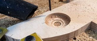
The grinder pulley, after the motor itself, is one of the most expensive elements of a grinding machine. The finished part costs at least 2,000 rubles. However, craftsmen use prefabricated wooden structures for their homemade products. Let's briefly consider the sequence of turning a pulley and rollers from thick plywood on a CNC machine.
| Illustration | Description of action |
| Using a special algorithm, the machine begins to sequentially cut out layers of the product exactly to the specified dimensions. | |
| These are the blanks we got. Cut the remaining rings to size. | |
| From the resulting rings we assemble a pulley and barrels, and fasten the parts with glue. | |
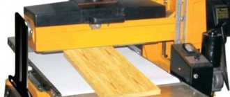
| Using a grinding machine, we polish the bevels so that the tape holds tightly. | |
| We process the resulting structures with impregnation. |
What does a homemade grinder consist of?
Let's look at the main components from which our homemade belt sanding machine is assembled.
Assembly drawing of the grinder
- Leading video
- Tension roller
- Driven roller
- Second driven roller
- Tensioner pulley lever
- Podruchnik
- Console
- Emphasis
- Frame
All components of the machine are easy to manufacture, and anyone can assemble it if desired. If you don’t have a welding machine, you can always negotiate with your neighbor for a small fee. Or allow you to use a homemade grinder if necessary. The grinder will be compact and not heavy.
Selecting parts for the recoil mechanism
Parts for the sliding gate mechanism
For sliding gates you will need:
- Channel – serves as a guide for rail models.
- Profile - a U-shaped structure, which is placed on the lower edge of the canvas and rollers are inserted into it.
- Roller bearings are plates on which bearings are mounted.
- The carriages are actually a roller mechanism. It absorbs the entire load from the weight of the sash and when it moves.
- Supporting – lateral rolling rollers. They are mounted on support posts and are designed to reduce vibrations.
- Catchers - fix the canvas in extreme positions and prevent the sash from rolling out of the guide.
- The knurling roller is the second part of the latch. It seems to roll onto the catcher and stop the movement.
The gate can be equipped with an electric drive. In this case, you will need an engine, automation and a remote control.
How to choose components
The rollers must match the weight of the gate.
Rollers for sliding gates, made by yourself or purchased, must meet a number of requirements:
- The roller mechanism is selected according to the weight of the structure. Otherwise, it will quickly fail.
- The recommended number is 5, one of which is transverse - prevents the canvas from swaying. 4 wheels distribute the load. Even if you install 8 rollers on the sash, it will only rest on 4. It is important to choose the right number, not the size.
- It is important to choose support brackets with convenient fastening and adjustability. In this case, their effectiveness does not depend on the distance between the supports.
- The knurling roller must be metal. Plastic wears out too easily and quickly.
- The supporting beam is also selected by weight. If the gate weight is less than 800 kg, take a beam with walls 4 mm thick. If the weight is greater - 5–6 mm.
The electric drive is selected according to power.
Grinder specification
Any belt sanding machine consists of a reliable frame and auxiliary parts. The main task when manufacturing a machine is to place the rollers in the same plane, otherwise the tape will constantly move to the side.
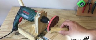
DIY grinder
You also need to pay attention to the speed of the drive. For this, a washing machine motor is perfect.
Before we begin production, we need to prepare:
- Square pipe 30x30x2 - 250 mm.
- Square pipe 25x25x1.5 - 1250 mm. Taking into account the cut.
- Channel No. 21 – 350 mm.
- Steel strip 50x8 – 700 mm. (With reserve). Or the eyes from the Gazelle spring earrings.
- Old door hinge.
- Sheet 170x190x4 for making a stop.
- Plywood sheet 500x200x8 mm.
- Bearings 201 – 9 pcs.
- Polypropylene couplings for 32 – 6 pcs.
- Polypropylene pipe PN20 – 250 mm.
- M8 hairpin – 1 pc.
- M12 hairpin – 1 pc.
- M8 nuts.
- Spring for tension arm.
- Angle No. 5.0 for mounting the engine to the frame.
- Motor from a washing machine.
Tape is still better
A belt grinder allows you to do everything a disk grinder can do, and much more. Therefore, next we will focus on how to make a belt sanding machine with your own hands. Amateurs, focusing on industrial designs, sometimes make very intricate grinders, see figure:
Homemade belt sanders
And this is justified: the design and kinematics of the belt grinder are very flexible, which makes it possible to successfully use scrap materials and old scrap metal. You just need to follow 3 principles:
- Do not do as in the second photo from the left: the abrasive side of the tape should only touch the workpiece. Otherwise, the abrasive will eat both the guide rollers and itself. The accuracy and cleanliness of processing during one work operation will be unpredictable;
- The design of the machine must ensure uniform tension of the belt, regardless of the nature of the operation performed;
- The speed of the belt must correspond to the nature of the operation being performed.
Kinematics and design
As mentioned above, there are many designs of grinders. When considering what and how to build a grinder for yourself, it is better to focus on industrial designs designed to be fully mechanized for precise and clean grinding of large-sized profiled parts: once it “sands” the blade of an airplane propeller or wind turbine properly, it can handle any other work.
Kinematic diagrams of grinders for the specified purpose are shown in Fig.:
Basic kinematic diagrams of belt grinding machines (grinders)
Pos. A is the most complex and perfect, with three rocker arms. If the length of the tension roller rocker arm is approx. 2 times less than the working one, then by adjusting the tension of the springs, it is possible to achieve uniform tension of the tape when the working rocker moves 20-30 degrees up and down. By tilting the bypass rocker, firstly, the machine is reconfigured for belts of different lengths. Secondly, in the same way you can quickly change the belt tension for different operations. The working branch of the belt can be any, except for the one running from the drive pulley to the tension roller, i.e. A grinder with 3 rocker arms is both horizontal and vertical.
The scheme with one misaligned rocker arm is used quite rarely in industry, because in principle, it does not allow achieving uniform tape tension. However, it gives accuracy that is quite sufficient at home and allows you to build a very good simple grinder.
What's good for what?
Now let's see what is possible to “squeeze” out of this or that circuit from the point of view of an amateur master. And then we’ll try to figure out how to make a grinder belt ourselves and do without custom-made turned parts.
How to use homemade machines and tools for your home workshop
The use of homemade machines and devices for the home workshop is aimed at solving several problems:
- Simplifying the metal processing process. When creating household items, a metal cutter or press is often required.
- Improving wood processing. Even to build a small shed or make a wooden shelf for your home, you need a power saw and other woodworking tools.
DIY lathe
Buying a ready-made tool is quite expensive, so the use of homemade machines and devices for the garage is becoming more and more relevant every day. Among the most common options for home tools are:
- carpentry workbench;
- device for quickly sharpening knives;
- device for sharpening metal drills;
- drilling machines;
- press;
- cutting disc machines.
Self-assembled drilling machine
Here are a few photos of do-it-yourself tools and devices from “homemade” people:
1 of 4
Drilling machine from improvised tools
Tool for bending profile pipes Cold forging machine
Blade sharpening tool
Tensioner and driven rollers
Made from propylene couplings, they are sold at any hardware store. Assembly drawing and step by step guide below.
Assembly drawing of the coupling
We assemble a package of couplings and D20 tubes onto the M12 stud; they serve as spacers between the bearings and install the bearings themselves. The photo below shows the entire assembly.
Step 1. Assembling the roller
Step 2. Tighten the nuts with a wrench
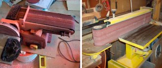
We pull together the assembled package into one whole. We process it with a grinder and a petal wheel on all sides, achieving a barrel-shaped shape.
In the same way we assemble the next two driven rollers. But we give the barrel shape only to the tension roller.
Schematic diagram of the grinder design and the principle of its operation
Before you begin selecting materials and components, it is important to understand the operating principle of the device.
Important! Some grinder parts will have to be purchased ready-made. Perhaps turn to the services of a turner.
There is nothing complicated in the design of the grinder from the mechanical side. It is important to determine the power of the unit and find components. In fact, the main element of the design is the motor and drive, which supplies torque to the rollers that rotate the belt. All elements can be made from metal, plywood, or even plastic. The photo shows a drawing of the grinder with dimensions.
Grinder device in the drawing
Let's look at the principle of operation of the grinder. With the help of a motor, a group of rollers is driven, one of which is the main one, or leading, the others are secondary. After turning on the device, the sanding belt begins to move. Using the regulators, you can shift the position of the rollers, which allows you to adjust the depth of tension and grinding and also its angle.
So, the main elements of the grinder are:
- Base.
- Electric motor.
- Straight roller with pulley.
- Tension rollers.
- Abrasive tape.
- Rack.
In addition, the design includes a rotating clamping mechanism.
Main components of the grinder
The unit, as we have already said, can be either manual or stationary. The design of a stationary device includes elements such as a rotary table with clamps, which is usually mounted on a workbench or stationary frame. The table can change the angle of inclination, rotate along its axis, and in some models – perpendicularly. The motor is driven either by a foot drive or by a drive motor that is attached directly to the tool on the frame. An old drill, grinder, or washing machine engine can serve as the “heart” of the grinder. The main thing is to ensure the necessary speed, which will allow you to process exactly those surfaces that you need.
Interesting fact! The power of the machine depends on the design of the belt mechanism and the volume of workpieces that you plan to process. The longer the sanding belt, the stronger the motor needs to be installed.
It is clear that over time the tension force of the tape may weaken; for this, options are provided for adjusting the tension system. This may be a spring clamp, and in some cases a regular bolt will help to adjust the height and angle of the rollers relative to each other.
Important! The rollers in the grinder must be installed strictly vertically relative to each other. Any change in the position of the rollers may cause the belt to break.
When thinking through the design, determine in advance how the work area will be cleaned of dust and eye protection. Typically, a folding acrylic glass or a stationary vacuum cleaner is used. You can see the design of this piece of equipment in industrial grinders.
Advice! Before deciding on the size of the belt and the width of the rollers, figure out for yourself what surfaces you plan to process, their dimensions and volume of work.
An example of the correct placement of rollers on a grinder
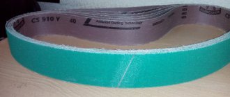
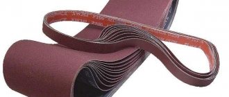
As we have already noted above, the issue of choosing a belt for a grinder is one of the most important. The speed and quality of surface treatment will depend on this. It is well known that sanding belts for grinders vary in length, width and degree of hardness (grain). Most often, the following tape sizes are used in machines of this type: 610, 915, 1230, 1600, 1830 mm in length, in width there are only two options -50 and 100 mm, however, experienced craftsmen can cut a tape of any width.
Important rules for choosing a belt for a grinder:
- The bottom fabric must be elastic in its structure. The fabric base better withstands surface tension.
- must withstand maximum angular speeds - at least 1500 rpm;
- the abrasive coating must be of high quality. Selected according to the material;
- the tensile strength must be at least 15%;
- the tape must be resistant to possible heating, which often occurs during long-term operation.
More information about the grinder device can be seen in this video:
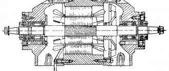
Design features
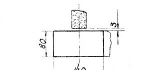
The drive roller deserves special attention. It is made massive in order to smoothly accelerate the belt to a given peripheral speed due to a significant moment of inertia. If you make the drive pulley from solid steel, it will turn with difficulty when starting. Therefore, it is made hollow or from duralumin grade D16 and higher. It is recommended to machine driven and tension rollers from light and hard duralumin, then there will be no need to make cavities.
The larger the diameter of the drive roller, the deeper the cavity should be.
The standard diameter of the drive pulley is 150 mm. The tension one is 100 mm in size, and the other two are 70 mm in size. Dimensions may vary slightly depending on the dimensions of the machine. The width of the parts corresponds to the size of the sanding belt with a small margin.
The generatrix of the drive pulley must be straight, otherwise the belt will bend along its entire length when rotating. It is reliably kept from sliding by the remaining rollers.
To avoid slipping of the sanding belt when the planes of the rollers do not coincide, a groove is made on the generating surface, corresponding in width and depth to the section of the belt. However, this design has a drawback: under heavy load, the tape slides onto the flange. A proven and reliable option is to use barrel rollers. In some cases, the products are covered with rubber material.
During installation on the grinder, you need to ensure that all the rollers are located in the same plane.
When processing, it is necessary to ensure the roughness of the forming surface in the range of 1.25–2.5 Ra. Large values will lead to wear of the belt, and on a surface that is too smooth it will turn. The “barrels” are installed on the shafts using bearing supports. The bearing assemblies are sealed to protect them from debris and abrasive dust. Bearings will be required to be self-aligning, not lower than 6th accuracy class. Their load-bearing capacity must correspond to the drive speed and planned loads. The prefabricated structure is fixed to the axis through cotter pins or through a collar and a fastening kit. For the drive pulley, you need to make a keyway in the mounting hole for installation on the engine shaft key or hole for the goujon.
The rollers must have a barrel-shaped profile to securely hold the rotating belt. The central part is made 2 mm higher than the edges.
Based on the connecting dimensions, a working drawing is drawn up, according to which the turner can produce parts.
Console left
The console is easy to assemble. The parts are welded according to the drawing. First, one pipe must be bent using a manual pipe bender or simply clamped securely in a vice.
After welding, clean the seams and blacken them to prevent corrosion. Or you can paint it with enamel.
This is what you should end up with.
Homemade grinder assembled without tape
If you need to change the maximum grinding speeds, then, as an option, you can change the diameters of the rollers.
The diameter of the drive pulley is calculated using this formula: D=V x 1000 x 60 / π x N
Or use a frequency regulator to change the speed. There are many options for implementation, the main thing is the desire to do everything with your own hands and not be afraid of difficulties.
Lathe device
It is impossible to make a lathe with your own hands without knowing its structure, so below we present its main parts:
- Drive unit. The basis of the mechanism generates power. For a low-power machine, a drive from a drill or washing machine is suitable;
- Bed. A steel corner or a wooden frame is suitable for manufacturing; this is a kind of load-bearing frame, so it must be strong to withstand vibrations;
- Tailstock. It is made by welding a corner to an iron plate. It is needed for fixation during processing of the manufactured device;
- Headstock. Installed on a movable frame, similar to a tailstock;
- Caliper. Acts as a support for the working part.
The rotational torque is transmitted by the engine to the working part using the following options:
The chain one is more expensive, it is more bulky, but it lasts a long time. In terms of its advantages and disadvantages, the friction one occupies a middle position. It is worth noting the fact that photos of a lathe with different gears are available on the Internet, and you can easily study them in detail.
The support is an extremely important part of the machine. It regulates both the amount of effort expended during work and the quality of the part.