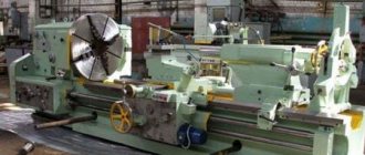
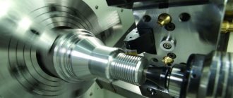
Presentation on technology “Design of a TV-6 lathe”
#Grade 7 #Technology #Teaching and methodological materials #Presentation #Subject teacher #School education
Design of the TV-6 lathe Author of the presentation; Baida Sergey Gennadievich Technology 7th grade
The beginning of the creation of fairly advanced screw-cutting lathes dates back to the 18th century, to the era of transformations carried out by Peter I. This process was headed by the talented Russian mechanic and inventor A.K. Nartov (1693-1756). He devoted about 25 years to the invention and improvement of lathes. 2. In the TV-6 machine brand, the letters TV mean screw-cutting lathe, and the number 6 is the model number. 3. Modern analogues of the TV-6 machine are the TV-7M table lathe (Russia), the JET BD-920 W floor lathe (Switzerland), etc.
Lathes
Device
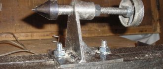
Tailstock 1 - special center, 2 - body, 3 - handwheel, 4 - clamps. 1 2 3 4 4
Caliper 1 - longitudinal slide, 2 - transverse slide, 3 - rotary slide, 4 - tool holder 1 2 4 3
Headstock 1 - body, 2 - handles, 3 - table of handle switching diagrams, 4 - chuck, 5 - reverse handle. 2 1 3 4 5
Laboratory work. Familiarization with the device of a screw-cutting lathe. 1. Get an assignment from your teacher to familiarize yourself with the design of the TV-6 screw-cutting lathe. 2. Name the main parts of the machine. Identify typical parts. 3. Familiarize yourself with the structure of the spindle, caliper, apron, headstock and tailstock. 4. Write down the names of the main parts of the machine in your workbook.
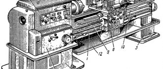
TV-6 machine controls: 1 - handle for changing the direction of feed of the support 2, 3 - handles for changing the spindle speed 4 - handle for fastening the tool holder 5 - handle for moving the cross slide 6 - handle for moving the upper slide 7 - tailstock flywheel 8 - handle for turning on the running gear screw 9 - handle for turning on the longitudinal mechanical feed of the caliper 10 - flywheel for longitudinal movement of the caliper 12 - power supply switch 13 - handle for turning on the lead screw or drive shaft 14 - handle for changing the feed amount. 4 1 2 3 5 6 7 9 8 10 12 13 14
Installing and securing the workpiece in a three-jaw chuck
Fastening the cutter
Scheme of turning the workpiece S - feed, t - depth of cut, D - diameter of the workpiece before turning, d - diameter after the cutter steamer.
Practical work. 1. Organize a training place for metal machining, observing labor protection requirements. 2. Receive the workpiece and cutters from the teacher and examine them carefully. 3. Insert the key into the hole of the three-jaw chuck and spread its jaws to the required amount. 4. Insert the workpiece correctly between the jaws and rotate the key to secure it. 5. With the help of the teacher (turning on the machine), check that there is no “beating” of the workpiece. If present, secure the workpiece again. 6. Install the proposed cutters into the tool holder. 7. Check their overhang and vertex locations using the rear center.
The design and principle of operation of a screw-cutting lathe for turning metal parts
The design and principle of operation of a screw-cutting lathe for turning metal parts.
Completed by technology teacher Krivtsova O.A. School 458, St. Petersburg.
Screw-cutting lathes
Designed for turning metal products and cutting threads on round parts, screws, bolts.
These machines are operated by workers by trade as turners.
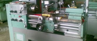
The following machines are used in school workshops: TV-6, TV-7, TV-4 (old model)
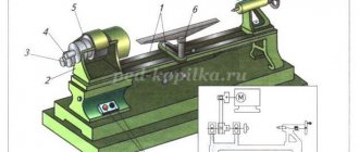
Textbook p. 66, device of a TV-6 screw-cutting lathe (detailed image).
The base of the machine is: cast iron bed
(7), installed on two pedestals (9,10).
The left cabinet contains an electric motor
(8) with a V-belt drive.
The frame is equipped with headstock and tailstock
(1, 6) - these are devices for fastening and rotating the workpiece.
A gearbox (3)
is mounted in the headstock to change the rotation speed of the spindle with a chuck in which the workpiece is mounted and rotated.
Apron (4)
with a support and a cutter are moved along the guides of the frame by mechanical feed from an electric motor or by manual rotation of the flywheel.
Lathe mechanisms
The transmission mechanism is used to transmit rotation from the gearbox spindle to the feedbox. The mechanism consists of a bracket on which the gears are mounted. The transmission mechanism is characterized by a gear ratio, and for the TV-6 machine it is:
i
= 24/60 * 40/64 = 1/4
For this machine, this gear ratio is constant, since replacement gears are not included with the machine.
The driving mechanism, using an electric motor, rotates the spindle with the chuck and the workpiece, and progressively moves the cutter.
The transmission mechanism is represented by a V-belt drive, a gearbox, a feed box, a screw drive and a drive shaft with gear and screw drives.
The machine has several types of motion transmissions: V-belt, toothed, rack and pinion (see picture in textbook No. 46)
Transmission mechanism
The driving mechanism, using an electric motor, rotates the spindle with the chuck and the workpiece, and progressively moves the cutter.
The transmission mechanism is represented by a V-belt drive, a gearbox, a feed box, a lead screw and a lead shaft with gear and screw drives.
The machine has several types of motion transmissions: V-belt, toothed, rack and pinion (see figure in textbook No. 46)
Transmission mechanism
The TVSh-2 universal screw-cutting small-sized lathe, one of the first school lathes, was produced in the 50s..60s of the last century. The machine can cut three threads and has three feeds.
TVSh-3 (TV-3) the first school screw-cutting lathes, produced in the 60s of the last century. The design of the machine was apparently based on a German-made machine. In the 70s, the TVSh-3 model was replaced by a more advanced screw-cutting lathe - TV-4.
The TV-4 machine replaced the outdated first school screw-cutting lathes TVSh-2 and TVSh-3 (TV-3) and was produced in the 70s of the last century.
The educational screw-cutting lathe TV-7 differs from the machine model TV-6 and TV-6M in the design of the headstock and gearbox. In the TV-7 model machine, the speeds are switched by transferring the drive belt and using a two-speed reduction box. Starting with this machine model, the training machines in this series received an additional three feeds and three metric threads. The spindle rotation speed is switched by transferring belts, so the two handles on the spindle head have disappeared. Starting with the TV-7 machine model, school machines received 8 feeds and learned to cut as many as 6 threads.
General view of the TV-7 screw-cutting lathe
General view of the TV-9 screw-cutting lathe
The TV-11 machine is a desktop universal screw-cutting lathe and is intended for all kinds of turning work, including precision, on centers, in a chuck, in a collet, for cutting threads with a part weight of 5 kg
16U04P General view of a screw-cutting lathe
The 16U04P screw-cutting lathe was produced in the USSR by the Kirovakan Precision Machine Tools Plant in Kirovakan (Vanadzor) and, currently, their production has been discontinued. The main purpose of the machine was to teach turning in schools, vocational schools, technical schools, and are widely used in laboratories, training and repair shops.
Photo of the headstock of the TV-6 screw-cutting lathe
Safe work rules!!
The work place at a lathe is a place with increased danger. Workpieces and machine parts rotating at enormous speed, flying chips, and a voltage of 380 Volts pose a threat to human life and health. Therefore, safety rules when working on wood and metal are the first thing a worker should know.
General provisions
Adults who have studied the necessary instructions and received instructions: introductory and on-the-job are allowed to perform turning work. The turner must be provided with special clothing: a robe or suit, boots, glasses. The worker must perform only those tasks assigned by the master. Work should be carried out in clean, repaired overalls on serviceable machines that have access to them. The workplace must be clean and orderly. It is prohibited to block passages. Eating and smoking are permitted in specially designated areas at certain times. It is prohibited to perform work under the influence of drugs that reduce the reaction rate (alcohol, drugs, medicines). The turner must observe the rules of personal hygiene.
Turner
To become a turner, you must have a specialized secondary education. Some educational institutions train turner apprentices, who, after completing the course, receive a 2nd or 3rd grade and can begin full-time work.
Representatives of this profession must understand drawings and be able to read them. They should also not only work on machines and other special equipment, but also know all the safety rules. A turner must have an understanding of the technology of processing parts and the properties of the materials with which he has to work.
Turner
The demand for the profession of a turner is quite high. Such specialists are required in construction, shipbuilding, automotive industry and many other enterprises and various organizations. The work of a turner is to process rotating workpieces to produce parts and products from various materials. By cutting, a specialist processes metal, plastics, plexiglass, and wood. Such a worker makes carvings, drills, countersinks, calibrates, etc.
Literature:
Open Internet sources:
https://stanki-katalog.ru/sprav_tv6.htm
https://www.proprof.ru/stati/careera/vybor-professii/o-professiyah/professiya-tokar
Textbook Technology 7th grade N.V.Sinitsa, P.S. Samorodsky, V.D. Simonenko - 3rd ed. 2017
Literature:
Open Internet sources:
https://stanki-katalog.ru/sprav_tv6.htm
https://www.proprof.ru/stati/careera/vybor-professii/o-professiyah/professiya-tokar
Textbook Technology 7th grade N.V.Sinitsa, P.S. Samorodsky, V.D. Simonenko - 3rd ed. 2017
