Information about the manufacturer of the screw-cutting lathe 1V62G
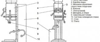
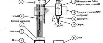
The manufacturer of the 1V62G screw-cutting lathe with a recess in the bed is the Astrakhan Machine Tool Plant , founded in 1944.
The main activity of the Astrakhan Machine Tool Plant is the production of metal-cutting, press-forging, abrasive-cutting, and woodworking equipment. In addition, the plant produces components for machine tools and equipment.
The plant produces screw-cutting lathes models 1V62G , 16V20 , 1V625 , 1V625M with a distance between centers of 750, 1000 and 1500 mm and a CNC lathe AS16M20F3 .
Machine tools produced by the Astrakhan Machine Tool Plant, ASZ
- 1A62G
- universal screw-cutting lathe, Ø 400 - 1V62G
- universal screw-cutting lathe, Ø 445 - 1В625м
– universal screw-cutting lathe, Ø 500 - 16B20
– universal screw-cutting lathe, Ø 445 - AS2116m
- tabletop drilling machine, Ø 16 x 100 - SMZh-172
- machine for cutting reinforcing steel, Ø 24
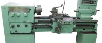
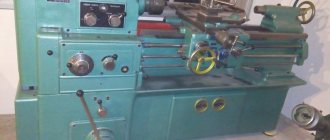
1V62G universal screw-cutting lathe with a recess in the bed. Purpose and scope
1V62G model lathe replaced the outdated 1A62G machine model with a recess in the bed.
Universal screw-cutting lathes 1V62G are designed for turning the external and internal surfaces of parts such as bodies of rotation of various axial profiles, including cutting metric, modular, inch and pitch threads on workpieces installed in centers or a chuck.
They are used for intra-Union supplies to enterprises in all sectors of the national economy.
It is most advisable to use machines in tooling and repair services in small-scale and single-piece production for finishing and semi-finishing work.
The universal screw-cutting lathe 1v62g allows you to perform the following types of work:
- Grooving and boring of cylindrical and conical surfaces
- End trimming
- segment
- Cutting metric, modular, inch and pitch threads
- Drilling and a number of other works
Operating principle and design features of the machine
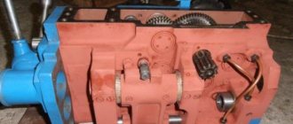
The spindle of the 1v62g machine receives 24 speeds (3 of which overlap) of rotation in the forward direction (11.5..1200 rpm) and 12 speeds in the reverse direction (18..1520) through the gears from the gearbox. To control the search, handles on the headstock are used.
A double-sided friction disc clutch , consisting of two independent halves, in the gearbox controls the starting, stopping and reversing of the spindle when the engine is turned on. The clutch is switched by a handle on the headstock or a handle on the apron of the machine.
The front end of the spindle is made in accordance with GOST 12593 (Flanged spindle ends for a rotary washer and flanges of clamping devices) (DIN 55027, ISO 702-3-75) for a rotary washer, with a centering short cone:
- Nominal cone diameter D = 106.375 mm, nominal spindle end size - 6
- The standard diameter of a three-jaw lathe chuck according to GOST 2675-80 is Ø 200 and Ø 250 mm, version - type 2 (for a rotary washer)
- The diameter of the through hole in the spindle is Ø 38 mm;
- The largest diameter of the processed rod is Ø 36 mm;
- The internal (tool) cone of the spindle is Morse 5;
- Limits on the number of direct spindle revolutions per minute (24-3=21 speed) - 10..1400 rpm;
- Limits of spindle reverse revolutions per minute (12 speeds) - 16..1800 rpm;
- The spindle is braked by a band when the friction clutch is turned off.
The machine uses standardized units produced by the Gomel Machine Units Plant:
- Apron 16B20P.061 or 067.0000.000
- Feed box 16B20P.070 or 077.0000.000
Feedbox 16B20P 070.000 and 077.0000.000 provides cutting of metric, inch, modular and pitch threads without the use of replaceable gears. To cut precise threads, the lead screw can be turned on directly, bypassing the feed box.
The feed box mechanism provides the following capabilities:
- Metric thread with pitch from 0.5 to 22.4 mm;
- Inch thread from 0.125 to 77 threads per 1 inch;
- Modular thread from 0.5 to 224 modules;
- Pitch thread from 0.125 to 77 pitches.
- Longitudinal feeds 0.036..22.4 mm/revolution (50 steps);
- Transverse feeds 0.018..11.2 mm/revolution (50 steps).
through a Ø 44 mm lead screw with a pitch of 12 mm, obtain the following threads:
through the Ø 30 mm drive shaft the following feeds can be obtained:
Feedbox 077.0000.000 allows you to additionally cut inch threads with 11 and 19 threads per inch without tuning the guitar.
The rigid box-shaped frame with hardened, ground guides has sufficient rigidity.
The spindle is mounted on precision rolling bearings.
The design of the tool holder ensures the stability of the tool fixation position. The machine apron is equipped with an original mechanism for switching off the feed of the caliper, which ensures high stopping accuracy on a rigid stop. A complex of fencing and blocking devices guarantees safe operation of the machine.
The machine is equipped with a feed box and an apron that has its own drive for accelerated movement of the caliper and carriage, which improves the dynamics of the machine at high speed, allowing you to cut inch threads of 11 and 19 threads per inch without replacing replaceable gears.
The gearbox, feed box and apron are equipped with an autonomous lubrication system. The design of the machine allows you to install electromechanical, hydraulic or pneumatic chucks on the spindle assembly for clamping workpieces. The machine is certified
All main parts of the machine are made of high quality steel, which ensures their reliable, long-lasting operation.
Heat-treated and ground bed guides, gears and shafts provide long service life and increased machining accuracy.
The tailstock is equipped with a mechanical unloading device that ensures smooth and easy movement.
The gearbox, feed box and apron are equipped with an autonomous lubrication system.
The design of the machine allows you to install electromechanical, hydraulic or pneumatic chucks on the spindle assembly for clamping workpieces.
The machine is certified to meet safety requirements.
The design and placement category of the machines in terms of operating conditions is UHL4 according to GOST 15150-69 (For operation in all climatic regions of neighboring countries in closed heated (cooled) and ventilated production premises).
The accuracy class of the machines is N according to GOST 8-82E.
Main characteristics of the screw-cutting lathe 1v62g
Basic technical data according to GOST GOST 18097-93 Screw-cutting and turning machines. Basic dimensions. Accuracy standards.
- The largest diameter of a Disk-type workpiece processed above the bed is Ø 445 mm;
- The largest diameter of the Disk-type workpiece processed above the recess is Ø 620 mm;
- The largest turning diameter of a workpiece of the Shaft type above the upper part of the support is Ø 220 mm;
- Distance between centers - 750, 1000, 1500 mm;
- The longest turning length is 650, 900, 1400 mm;
- Spindle speed - 10..1400 rpm;
- Main drive power - 7.5 kW
- The total weight of the machine is 2.2; 2.4; 2.8 t
Modifications of the universal screw-cutting lathe 1V62G
16B20 - a machine without a recess in the bed.
16B20A - a machine with a mechanical drive of the upper support.
1V62G - a basic machine with a recess in the bed. Machine bed mod. 1V62G has a recess covered by a removable bridge. This makes it possible to process larger (up to 620 mm in diameter) workpieces such as disks, rings and flanges when the bridge is removed.
1V62GA - a basic machine with a recess in the bed. Machine with mechanical drive of the upper support.
1V62GU - Ø 445 This design uses a headstock with a simplified kinematic diagram and a spindle assembly of increased accuracy and rigidity. A simplified kinematic diagram increases the reliability of the machine without compromising its technological capabilities when turning and cutting threads, both metric and pipe, without additional adjustment of the gearbox.
16G20AS - Ø 445 universal high-power screw-cutting lathe
1B625 - Ø 500 basic universal screw-cutting lathe with a recess in the bed
1B625M - Ø 500 is a promising development of the Astrakhan Machine Tool Plant - screw-cutting lathe model 1B625M. Designed for a variety of turning operations, including cutting metric, modular, inch and pitch threads on workpieces installed in centers or a chuck. The design and placement category of the machine in terms of operating conditions is UHL4 according to GOST 15150-69.
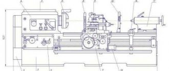
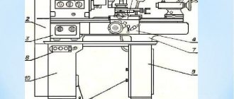
Location of the main components of the 1V62G screw-cutting lathe
Location of the main components of the 1v62g lathe
Specification of the main components of the 1V62G screw-cutting lathe
- Gearbox - 1V62G.81.000
- Electrical cabinet - 1V62G.83V.000
- Feed box - 16B20P.070.000
- Front headstock - 1V62G.24.01
- Chuck guard - 1V62G.93.01
- Bed - 1V62G.12.000
- Carriage and support - 1В62Г.35.000*
- Apron - 16B20P.061.000
- Caliper guard - 1V62G.30.000-01
- Rear headstock - 1V62G.30.000
Purpose and scope
Machining parts with different surfaces and shapes is the main area where the 1V62G universal machine is used. Thanks to this device, craftsmen can easily cut threads with various characteristics. The device is suitable for enterprises in any sector of the national economy. Helps organize intra-Union supplies. The production of small series, single products - this is where the use of machines will be relevant.
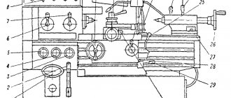
Location of controls for screw-cutting lathe 1V62G
Location of controls for lathe 1v62g
List of controls for screw-cutting lathe 1V62G
- Handle for setting the spindle speed range
- Spindle speed setting handle
- Handle for setting normal and increased thread pitch
- Handle for setting right and left threads (feed)
- Handle for setting the feed rate and thread pitch
- Handle for selecting the type of work (carving or feed) and thread type
- Handle for setting the feed rate and thread pitch, as well as turning off the feed mechanism when cutting threads directly
- Main drive friction clutch control handle (interlocked with handle 14)
- Handwheel for manual carriage movement
- Rack and pinion on/off handle
- Push-button station for turning on and off the main drive electric motor, as well as “STOP/EMERGENCY STOP”
- Handle for turning on the feed when it is turned off as a result of overload
- Handle for controlling mechanical movements of the carriage and cross slide of the caliper
- Main drive friction clutch control handle (interlocked with handle
- Tailstock quill movement flywheel
- Handle for securing the tailstock to the frame
- Tailstock Cross Screws
- Tailstock quill fastening handle
- Button for turning on the electric motor for driving rapid movements of the carriage and cross slide of the caliper
- Lead screw nut on/off handle
- Handle for manual movement of the tool slide of the caliper
- Handle for turning and securing the cutting head
- Screw securing the carriage to the frame
- Local lamp switch
- Handle for manual movement of the cross slide of the caliper
- Coolant adjustment nozzle
- Button for lubrication of the carriage guides and cross slides of the caliper
- Electric coolant pump switch
- Signal light “Machine connected to network”
- Input circuit breaker
- Warning light "Main motor on"
- Longitudinal movement stop
- Handle for switching the pitch of an inch thread from 11 to 19 threads per inch
- Handle for turning on and off the mechanical drive of the upper support (slide)
Table of threads and feeds of a screw-cutting lathe 1v62g
Tailstock
The tailstock moves along the same guides as the apron. The movement is carried out manually; the headstock is fixed in the desired position by turning the handle.
A quill with a conical hole is installed in the tailstock. A center is installed in it to support the rear end of the workpieces. By design, centers are divided into two types - rotating and stationary. The movement of the quill is carried out by a flywheel located on the rear side. The quill is fixed with a separate handle.
In addition to centers, the tailstock can contain a tool for making and processing internal holes in workpieces. The tailstock can be connected to the caliper and used for power feed drilling.
Additionally, there are longitudinal guides that allow the machine to produce surfaces in the shape of a gentle cone. This headstock design improves the technical characteristics of the 1K62 lathe.
Kinematic diagram of a screw-cutting lathe 1V62G
Kinematic diagram of the 1v62g lathe
The main movement of the 1V62G machine - rotation of the spindle - is carried out from electric motor 1 through a V-belt drive by pulleys 2 and 3, then through the headstock mechanism (gearbox).
The feed movement is carried out from the output shaft XII of the headstock through the gearbox and feedbox mechanisms, which provide an accurate kinematic connection between the rotation of the spindle and the movements of the tool (cutter) fixed in the support tool holder.
How to repair 1K62
It must be said that the technical characteristics of this lathe are distinguished by good performance. Therefore, the 1K62 instruction manual guarantees its stable operation for a very long time. But the device needs to be monitored and periodically carried out maintenance and repair. To do this, do:
- Running in the machine. All feeds and speeds are checked;
- The accuracy of the machine is determined;
- The guides are cleaned.
If partial disassembly takes place, the parts are washed and wiped well. Repair of a 1K62 lathe helps to identify unusable components and assemblies. If they cannot be restored, new ones are installed. External non-working surfaces are usually painted with bright paint.
Operating procedure on the machine
Setting spindle speeds
Giving the spindle the required rotation speed is carried out by installing handles 1 and 2 (Figure 9) according to the instructions in the table mounted on the front side of the machine's headstock.
On the left side of this table the frequencies of direct rotation of the spindle are given and the positions of handles 1 and 2 are indicated at which they are ensured.
Handle 1 is installed in one of four positions (its position is aligned with the rows of frequency numbers marked above its hub, at the bottom of the right side of the table). Handle 2 is set by circular rotation to a position that ensures that the number marked on the side surface of its hub (corresponding to the number selected in the table) coincides with the pointer marked on the table above this handle.
Feed setting
The feed values are set with handle 6 (Figure 9) set to the “feed” position (when the hub protrusion is aligned with the corresponding symbol printed on the table mounted on the feed box casing), handles 5 and 7 in accordance with the values indicated in the upper right part of the table mounted on the front side of the headstock housing.
Having adjusted the spindle rotation speeds in accordance with the selected series of feeds, find the desired feed in this line and, by its location in the title and subtitle of the corresponding column, find instructions for installing handle 5 (in one of positions I, II, III or IV) and handle 7 ( to one of positions A, B, C or D).
Installation of the handles in the positions determined in this way is carried out by aligning the protrusions of these handles with the corresponding symbols indicated in the table located on the left side of the feed box housing.
The table located on the headstock gives the values of the longitudinal feeds. The amount of transverse feed is equal to half of the longitudinal feed.
Setting up machines of models 1V62G; 16B20; 1V62GA; 16B20A for threading.
SETTING FOR CUTTING METRIC AND INCH THREADS WITH THE PARAMETERS INDICATED IN THE MIDDLE PART OF THE TABLE ATTACHED ON THE FEED BOX CASING.
With factory installed replacement gears in combination (Figure 10, Figure 11)
K/L x L/N = 40/86 x 86/64 (2)
It provides cutting of metric and inch threads with the parameters (pitch, mm and number of threads per inch, respectively) indicated in the middle part of the table (top and bottom four lines, respectively).
Scheme for installing bearings on a 1v62g screw-cutting lathe
Bearing installation diagram for screw-cutting lathe 1v62g
List of bearings for screw-cutting lathe 1v62g
Adjusting the spindle bearings of a screw-cutting lathe 1v62g
Spindle bearings are adjusted at the factory and do not require additional adjustment.
In case of emergency, the consumer can resort to adjusting the spindle supports using highly qualified specialists.
However, before this it is necessary to check the rigidity of the spindle assembly. To do this, a jack with a laboratory-tested dynamometer is installed on the frame under the spindle flange, and a force directed vertically from bottom to top is applied to its flange through a gasket that protects the spindle from damage.
The spindle displacement is controlled by a certified indicator with a division value of no more than 0.001 mm, installed on the spindle head and touching the upper part of the spindle flange with its measuring tip. A spindle deflection of 0.001 mm should occur with an applied force of at least 45-50 kgf. If the load value at a displacement of 0.001 mm is significantly lower than specified, then the bearing must be adjusted.
Spindle bearing set:
- 33. Front bearing No. 4-3182120 - double-row radial roller
- 18. Rear bearing No. 6-8116 - single thrust ball
- 17. Rear bearing No. 6-7216 - tapered angular contact roller bearing, 80x140x26
Passport
The passport of the 16B20 lathe is included in the “Operating Instructions” supplied with it. Basic information about the released and tested copy of the machine is given in the chapter “Acceptance Information”. Its first part is devoted to checking electrical equipment. At the beginning there is the model, serial number and manufacturer of the electrical cabinet, and at the end there is the signature of the person responsible for testing it.
The next section contains data on conservation, indicating the date of this operation, state standards and the validity period of conservation, and at the end there is the signature of the person in charge. This is followed by packaging information (also signed by the person in charge), and the chapter ends with the “Acceptance Certificate” section. It indicates the designation, modification and serial number of the machine, but does not contain a table with technical test data, which in earlier times usually completed the lathe's passport. Instead, a list of GOSTs and technical specifications is provided, the requirements of which it fully complies with based on the results of “inspection and tests”.
YOU CAN DOWNLOAD YOUR PASSPORT HERE.
Adjustment of spindle units with bearing No. 3182120
Spindle head of lathe 1v62g with bearing No. 3182120
The spindle bearings (front - double-row roller and rear bearings) are adjusted at the factory and do not require any adjustment.
During repairs, the bearings are adjusted as follows. The front spindle bearing is adjusted by nut 43 (Fig. l1), located inside the headstock housing, in the following order: release the screw and turn the nut in the required direction. By turning this nut, axial movement of the inner ring of the bearing on the conical neck of the spindle is carried out.
When the nut is turned to the right, the inner ring of the bearing is tensioned onto the conical journal of the spindle. In this case, the ring is deformed, its outer diameter increases, ensuring a tight fit of all rollers to the surfaces of the inner and outer rings of the bearing, which reduces the radial clearance in the bearing. After adjustment, tighten the screw again.
Technical characteristics of bearing 3182120
Bearing No. 3182120 is a double-row radial roller, with short cylindrical rollers, with a flangeless outer ring, with a conical bore (1:12), a groove and holes for introducing lubricant.
A set of rolling elements with an inner ring can move relative to the outer ring in both directions. Double-row roller bearings are capable of providing high load capacity and rigidity with their small dimensions (primarily the distance between the outer and inner rings). This type, like most roller bearings in this series, is currently produced only in high-precision, second or fourth class, since the main area of application is precision machines, during which unacceptably high runout is used. Products with low degrees of accuracy (6) are available from storage. The main manufacturer of bearings of this design has always been considered the Moscow GPZ-1, but now its production has been transferred to the city of Volzhsky, to a branch of the Aviation Bearing Plant at 15 GPZ (all plants are united under the auspices of the European Bearing Corporation), so bearings marked GPZ-1 are sold with storage (or there may also be counterfeit goods). Currently, two different modifications are being manufactured - 2-3182120K, 4-3182120K, which differ in accuracy class. In addition to these factories, this type was also produced by 10 gas processing plants (Rostov-on-Don). After the collapse of the domestic industry, there was an oversupply of bearings of this type on the market, which were removed from equipment, sold from warehouse balances, etc. Among such products there can be both very high quality and inexpensive, and unsuitable for use.
You can buy factory bearings, the long-term performance of which is guaranteed by the manufacturer, with minimal trade margins from official representatives of EPK (the estimated price is about 6,500 rubles, and the accuracy class does not affect it much), illiquid products and bearings from storage can be purchased from companies located in major industrial centers of the past.
Imported bearings of this size are designated NN3020K (the presence of the letter K in the number is mandatory, as it indicates a tapered fit). In Russia, the most common products are from the following manufacturers: FAG, SKF, NACHI, IBC. Just like domestic bearings, imported ones are also widely sold as non-liquid items, primarily these are products of Eastern European manufacturers - URB (Romania) and FLT (Poland), produced and imported into the country during the existence of the Union. Chinese bearings CX, SZPK, ZWZ and others can also be sold under the guise of imported ones.
Dimensions and characteristics of bearing 3182120 (NN3020K)
- Inner diameter (d): – 100 mm;
- Outer diameter (D): – 150 mm;
- Width (H): – 37 mm;
- Weight: – 2.17 kg;
- Roller dimensions: - 11x11 mm;
- Number of rollers: - 60 pcs;
- Dynamic load capacity: - 160 kN;
- Static load capacity: - 247 kN;
- Maximum rated speed: - 6000 rpm.
Bearing diagram 3182120
Photo of bearing 3182120
Technical characteristics of bearing No. 8116
Bearing 8116 is a single thrust ball bearing used in units with axial loads and low speeds.
During installation, it should be taken into account that one of the rings that fits onto the shaft has a diameter 1 millimeter smaller than the one that goes into the housing. Misalignment of seats must not be allowed! In our country it is produced at 2 gas processing plants (it is under this marking that you can buy the 8116 bearing almost everywhere), as well as on a smaller scale at the Kursk Thrust Bearing Plant (20 gas processing plants) and the Samara Bearing Plant SPZ-4.
Imported bearings of this size have the number 51116.
Dimensions and characteristics of bearing 8116 (51116)
- Inner diameter (d): – 80 mm;
- Outer diameter (D): – 105 mm;
- Width (H): – 19 mm;
- Weight: – 0.425 kg;
- Ball diameter: - 9.525 mm;
- Number of balls: - 27 pcs;
- Dynamic load capacity: - 44.9 kN;
- Static load capacity: - kN;
- Maximum rated speed: - 3000 rpm.
Diagram of bearing 8116 (51116) of lathe 1e61pm
Photo of bearing 8116 (51116)
Technical characteristics of bearing No. 7216
Bearing 7216 is a roller, angular contact, tapered (or this type is also called “with tapered rollers”), single row.
This type is produced in accordance with TU 37.006.162-89. The contact angle of this type ranges from 10 to 18°, which allows it to be used under conditions of high radial and axial loads. This bearing is currently produced at the following industry enterprises:
15 GPZ (Volzhsky Bearing Plant) is the main manufacturer that supplies its products directly to automotive manufacturing plants. It forces the Samara plant out of the market due to lower prices and quality, which many find higher. Marking VPZ (formerly VPZ-15 or 15 GPZ). The high-precision bearing (4) is manufactured by another enterprise of the EPK holding - the Volzhsky branch of the Aviation Bearing Plant, and the price for this product is significantly higher.
9 GPZ (Samara Bearing Plant) - has long been famous for its products, but is losing out to the price competition of VPZ. Marking SPZ GROUP;
23 GPZ (Vologda), VBF marking - Vologda bearings are considered among car enthusiasts to be the best domestic ones, but it is extremely difficult to buy them, so this statement is more like a myth;
28 GPP (Lutsk, Ukraine) - not widely distributed, as a result of which there are still few reviews about their performance and durability.
An imported roller bearing of this type is designated according to the international nomenclature - 30216.
Dimensions and characteristics of bearing 7216 (30216)
- Inner diameter (d): – 80 mm;
- Outer diameter (D): – 140 mm;
- Width (H): – 28.5 mm;
- Weight: – 1.65 kg;
- Roller dimensions: - 13.8/15.01 x 17.39 mm;
- Number of rollers: - 20 pcs;
- Dynamic load capacity: - 151 kN;
- Static load capacity: - 183 kN;
- Maximum rated speed: - 3400 rpm.
Bearing diagram 7216 (30216)
Electrical circuit of the machine 1V62G
Electrical circuit of lathe 1v62g
Electrical equipment. Parameters of machine electrical circuits
- Electrical cabinet, model 1V62G.83V.000
- Supply network: voltage - 380 V, current - three-phase, frequency - 50 Hz
- Control circuit: voltage - 110 V, current - alternating
- Local lighting circuit: voltage - 24 V, current - alternating
- Signaling circuit: voltage - 22 V, current - alternating
- Rated current (sum of rated currents of simultaneously operating electric motors) - 17.6 A
Electrical equipment of screw-cutting lathe 1V62G
The electrical equipment of the machine is designed to connect power units, lighting and signaling devices to a three-phase alternating current network with a solidly grounded neutral wire, as well as to ensure their protection from overloads, short circuit currents and other factors. All relay contact and other electrical equipment used is simple in design and has proven itself well when working on machine tools. This ensures reliable operation of electrical equipment and the possibility of its maintenance by semi-skilled specialists.
Electrical equipment, with the exception of a few devices, is mounted in electrical cabinet 2 (Figure 8), located on the rear side of the headstock housing.
The power circuit of the machine includes three three-phase asynchronous electric motors, safety devices and switches.
The control circuit includes relay contact and other devices located in the cabinet, as well as a push-button station 11 SB1.1 SB1.2 (Figure 9) for starting and stopping the main drive, limit switches 19 SQ1 for controlling the accelerated motor and limit switches SQ2, SQ3 locking the chuck guard and gearbox cover.
The local lighting circuit EL1 ensures the operation of a machine lamp with a flexible stand and a built-in switch. Illumination 1500 lux.
The signaling circuit includes signal lamps 29 (HL1) and 31 (HL2).
Description of the operation of the electrical circuit of the 1V62G screw-cutting lathe
Turning on the input switch QF1 (Figure 12) when there is voltage in the network is accompanied by the lighting of the HL1 lamp.
The start of the electric motor of the main drive M1 is carried out when the input switch QF1 is turned on by pressing the button SB1.1 of the push-button station, which closes the coil circuit of the magnetic starter KM1. In this case, the magnetic system of the starter is triggered and closes its normally open main and auxiliary contacts KM1, that is: the magnetic starter KM1 will switch to self-power, because one of its auxiliary contacts will close the coil power circuit parallel to the SB1.1 button and when the latter is released the circuit will not break; the electric motor of the main drive M1, powered by the power circuit through the closed main contacts of the KM1 starter, will turn on;
The electric motor of the main drive M1 is stopped by pressing the button of the push-button station SB1.2. In this case, the coil circuit of the magnetic starter KM1 will open, it will be de-energized, all contacts of the starter will open, i.e. the electric motor M1 will turn off, the self-supply circuit of the magnetic starter will break.
The rapid movement motor M3 is started by pressing the jog button built into the apron handle and acting on the limit switch SQ1. The normally open contact of the limit switch, when the button is pressed, closes the power circuit of the electromagnet coil of the KM2 starter, which in turn closes the KM2 contacts of the power circuit of the high-speed motor. Switch QF2 is always on.
When the jog button SQ1 is released, the control circuit will open and the starter coil will be de-energized, i.e. the KM2 contacts will open and the M3 electric motor will turn off. Starting and stopping the electric pump M2 is carried out using switch SA1 installed on the front panel of the electrical cabinet.
Technical characteristics of the machine 1V62G
| Parameter name | 16В20 | 1V62G | 1V625M |
| Main settings | |||
| Accuracy class according to GOST 8-82 | N | N | N |
| The largest diameter of the workpiece above the bed, mm | 445 | 445 | 500 |
| The largest diameter of the workpiece above the support, mm | 220 | 220 | 290 |
| The largest diameter of the workpiece above the frame recess, mm | — | 620 | 690 |
| Maximum workpiece length (RMC), mm | 750,1000,1500 | 750,1000,1500 | 1000,1500,2000 |
| Maximum turning length, mm | 650,900,1400 | 650,900,1400 | 900,1400,1900 |
| Maximum mass of the workpiece in the chuck, kg | |||
| The largest mass of the workpiece in the centers, kg | |||
| Spindle | |||
| Diameter of through hole in spindle, mm | 54 | 54 | 60 |
| Maximum rod diameter, mm | |||
| Number of speed steps for direct spindle rotation | 24 | 24 | 24 |
| Spindle direct rotation frequency, rpm | 10…1400 | 10…1400 | 10…1400 |
| Number of spindle reverse rotation frequency steps | 12 | 12 | 12 |
| Spindle reverse rotation frequency, rpm | 16..1800 | 16..1800 | 16..1800 |
| Size of the inner cone in the spindle | M5 | M5 | M5 |
| Spindle end according to GOST 12593-72 | 6K | 6K | 6K |
| Submissions | |||
| Maximum longitudinal movement of the caliper carriage, mm | 650, 900, 1400 | 650, 900, 1400 | 900, 1400, 1900 |
| Maximum lateral movement of the caliper, mm | 280 | 280 | 302 |
| Maximum lateral movement of the upper support (slide), mm | 130 | 130 | 130 |
| Number of longitudinal/transverse feed stages | 50/ 50 | 50/ 50 | 50/ 50 |
| Limits of longitudinal feed speed, mm/rev | 0,018..22,4 | 0,018..22,4 | 0,036..22,4 |
| Transverse feed speed limits, mm/rev | 0,009..11,2 | 0,009..11,2 | 0,018..11,2 |
| Speed of fast movements of the caliper, longitudinal/transverse, m/min | 4/ 2 | 4/ 2 | 4/ 2 |
| Longitudinal movement per dial division, mm | 1 | 1 | 1 |
| Longitudinal movement per vernier division, mm | 0,1 | 0,1 | 0,1 |
| Transverse movement of the caliper per dial division, mm | 0,05 | 0,05 | 0,05 |
| Movement of the slide by one division of the dial, mm | 0,05 | 0,05 | 0,05 |
| Number of metric threads to be cut | 36 | 36 | 36 |
| Limits of pitches of cut metric threads, mm | 0,5..224 | 0,5..224 | 0,5..224 |
| Number of inch threads to be cut | 45 | 45 | 45 |
| Limits of pitches of cut inch threads | 77..0,125 | 77..0,125 | 77..0,125 |
| Number of modular threads to be cut | 36 | 36 | 36 |
| Limits of pitches of cut modular threads | 0,5..224 | 0,5..224 | 0,5..224 |
| Number of cut pitch threads | 45 | 45 | 45 |
| Limits of pitches of cut pitch threads | 77..0,125 | 77..0,125 | 77..0,125 |
| Overload fuse | There is | There is | There is |
| Blocking longitudinal and transverse feeds | There is | There is | There is |
| Switching longitudinal stops | There is | There is | There is |
| Surface roughness of a workpiece made of structural steel during finishing turning, microns, no more | Ra 2.0 | Ra 2.0 | |
| Tailstock | |||
| Maximum length of movement of the tailstock quill, mm | 150 | 150 | 150 |
| Maximum movement of the tailstock, mm | ±15 | ±15 | ±15 |
| Electrical equipment | |||
| Number of electric motors on the machine | 3 | 3 | 3 |
| Main drive electric motor, kW | 7,5 | 7,5 | 7,5 |
| Accelerated motion drive, kW | 0,75 | 0,75 | 0,37 |
| Cooling pump electric motor, kW | 0,12 | 0,12 | 0,12 |
| Total power, kW | 8,37 | 8,37 | |
| Dimensions and weight of the machine | |||
| Machine dimensions (length width height) (RMC 1000), mm | 2800 1190 1450 | 2800 1190 1450 | 2800 1370 1700 |
| Machine weight (RMC 1000), kg | 2450 | 2430 | 2430 |
- Screw-cutting lathes 16V20, 16V20A, 1V62G, 1V62GA, 1V625. Operating manual, 2004
- Screw-cutting lathes 16V20, 1V62G, 1V625M. Operating manual 16В20.00.000 РЭ
- Screw-cutting lathes 16V20, 1V62G. Operating manual 1V62G.00.000 RE3, 1993
- Acherkan N.S. Metal-cutting machines, Volume 1, 1965
- Denezhny P.M., Stiskin G.M., Thor I.E. Turning, 1972. (1k62)
- Denezhny P.M., Stiskin G.M., Thor I.E. Turning, 1979. (16k20)
- Batov V.P. Lathes., 1978
- Modzelevsky A. A., Muschinkin A. A., Kedrov S. S., Sobol A. M., Zavgorodniy Yu. P., Lathes, 1973
- Tepinkichiev V.K. Metal cutting machines, 1973
- Skhirtladze A.G., Novikov V.Yu. Technological equipment for machine-building industries, 1980
- Chernov N.N. Metal cutting machines, 1988
Bibliography:
Related Links. Additional Information
- Classification and main characteristics of turning
- Selecting the right metalworking machine
- Multi-start thread. Methods for cutting multi-start threads on a lathe
- Graphic signs for lathes
- Friction clutch of a screw-cutting lathe
- Methodology for checking and testing screw-cutting lathes for accuracy
- Directory of lathe manufacturing plants
- Directory of factories producing metal-cutting machines
- Directory of lathes
- Articles on the topic
Home About the company News Articles Price list Contacts Reference information Interesting video KPO woodworking machines Manufacturers
All-Russian Product Classifier (OKP) OK 005-93
Industry classifier of metal-cutting machines OK 005-93
The classification of machine tools in the All-Russian Product Classifier OKP OK005-93 is used to solve problems of product cataloging, including the development of catalogs and systematization of products in them according to the most important technical and economic characteristics. This purpose of the classifier is of interest for valuation activities, in particular for the construction of price list catalogs and databases containing price information.
OKP is the most detailed classifier of machine tools, including types of products. The structure of six-digit codes is as follows:
XX 0000 - product classes;
XX X000 - subclasses;
XX XX00 - groups;
XX ХХХ0 - subgroups;
XX XXXX - species.
Example of coding in OKP:
38 0000 – (class) Metalworking and woodworking equipment;
38 1000 – (subclass) metal-cutting machines;
38 1100 – (group) Turning machines
38 1140 – (subgroup) Lathe-backing machines, combined lathes and lobe lathes;
38 1148 – (type) Chuck lathes and screw-cutting lathes.
Using OKP codes helps you quickly find the information you need, which is very important when revaluing. As databases are created for individual types of machinery and equipment, the task of integrating them on the basis of a single classifier of assessment objects, for which it is advisable to use OKP, becomes increasingly important