Even with the advent of new methods of forming parts (combustion casting, laser and plasma cutting, etc.), metal cutting remains relevant. Its advantage is the versatility of obtaining products of different shapes. These are flat and three-dimensional bodies, figures of rotation, made on planing, milling, lathes and other metal-cutting units. They are used in industry, for servicing and repairing vehicles (cars, ships, construction and road vehicles).
It is often more profitable to use a full-size machine, which requires space for installation and a serious approach to maintenance. These inconveniences are nothing compared to its capabilities and accuracy, higher than that of a desktop or smaller version. This unit can be used for:
- Single or small-scale production of parts.
- Tool and repair production.
- Semi-finish or fine finishing only.
TIP: before choosing a model, study the recommendations of experienced specialists and reviews on specialized forums.
It is preferable to use new equipment or machines after a full restoration.
Information about the manufacturer of the screw-cutting lathe 16B20p
Manufacturer of universal lathes 16B20p - Moscow Machine Tool Plant named after. A.I. Efremova , founded in 1857.
The first universal screw-cutting lathes with a gearbox for the first time in the USSR began to be produced at the Moscow Machine Tool Building named after. A.I. Efremov in 1932 and received the names DIP-200, DIP-300, DIP-400, DIP-500 ( DIP
- Catch up and Overtake), where 200, 300, 400, 500 is the height of the centers above the frame.
As the design of the machines improved, the plant produced more and more modern models - 1A62, 1K62, 16K20, MK6056.
Machine tools produced by the Moscow Machine Tool Plant Krasny Proletary, KP
- 1A62
- universal screw-cutting lathe, Ø 400 - 1K62
- universal screw-cutting lathe, Ø 400 - 1K62B
– high-precision universal screw-cutting lathe, Ø 400 - 1K282
- eight-spindle vertical lathe, Ø 250 - 1K620
- universal screw-cutting lathe with variator, Ø 400 - 1K625
- lightweight screw-cutting lathe with an increased line of centers, Ø 500 - 16A20F3
– CNC lathe, Ø 400 - 16B20P
- high-precision screw-cutting lathe, Ø 400 - 16K20
– universal screw-cutting lathe Ø 400 - 16K20VF1
- universal high-precision screw-cutting lathe with digital display, Ø 400 - 16K20M
- mechanized screw-cutting lathe, Ø 400 - 16K20P
- high-precision screw-cutting lathe, Ø 400 - 16K20PF1
- high-precision screw-cutting lathe with digital display, Ø 400 - 16K20F3
- CNC lathe, Ø 400 - 16K20F3S32
- CNC lathe, Ø 400 - 16K20T1
- lathe with operational control, Ø 500 - 16K25
- lightweight screw-cutting lathe with an increased line of centers, Ø 500 - 162
— universal screw-cutting lathe, Ø 420 - 1622
— universal screw-cutting lathe, Ø 120 - 1730
— semi-automatic multi-cutting lathe, Ø 410 - DIP-40 (1D64)
- universal screw-cutting lathe, Ø 800 - DIP-50 (1D65)
- universal screw-cutting lathe, Ø 1000 - DIP-200
– universal screw-cutting lathe, Ø 400 - DIP-300
– universal screw-cutting lathe, Ø 630 - DIP-400
– universal screw-cutting lathe, Ø 800 - DIP-500
– universal screw-cutting lathe, Ø 1000 - MK6046, MK6047, MK6048
- universal screw-cutting lathe, Ø 500 - MK6056, MK6057, MK6058
- universal screw-cutting lathe, Ø 500 - MK-3002
- table lathe, Ø 220
Passport for screw-cutting lathe 16K20P.
This instruction manual for the “Universal screw-cutting lathe 16K20” contains information necessary both for the maintenance personnel of this machine and for the employee directly involved in working on this machine. This manual is an electronic version in PDF format of the original paper version. This documentation contains the Passport and Manual (instructions) for the operation of the universal screw-cutting lathe 16K20P . Contents of this documentation:
Contents of the Certificate of screw-cutting lathe 16K20P:
- Introduction
- Unpacking and transporting the machine
- Removing anti-corrosion coatings
- Machine installation
- Preparing the machine for start-up
- Machine lubrication
- Electrical equipment of the machine
- Pneumatic equipment of the machine
- Controls
- Starting up the machine and some operating conditions
- Instructions for the use and installation of chucks and steady rests
- Machine mechanics
- Brief description of the main components and their regulation
- Kinematic diagram of the machine
- Bearing layout diagram
- Typical possible malfunctions.
- Repair.
- Instructions for carrying out accuracy control
- Machine passport
- Applications
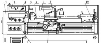
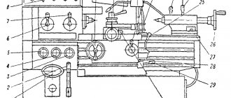
Location of controls for screw-cutting lathe 16B20P
Location of controls for screw-cutting lathe 16B20p
List of controls for screw-cutting lathe 16B20P
- Spindle speed setting handle
- Spindle speed setting handle
- Handle for setting normal and increased pitch and dividing into multi-start threads
- Handle for setting right or left thread
- Handle for selecting thread type and type of work (threading or feeding)
- Feed or thread setting handle
- Feed or thread setting handle
- Handwheel for manual longitudinal movement of the caliper carriage
- Lead screw nut on/off handle
- Longitudinal feed dial clamp handwheel
- Button for disengaging the rack and pinion gear when cutting threads
- Caliper lateral movement handle
- Button for turning on the mechanical movement of the upper support (cutting slide)
- Clamp handle against turning the lead screw to move the upper support (cutting slide)
- Upper slide (cutter slide) feed handle
- Handle for rotating, indexing and clamping the cutting head
- Handle for turning on, stopping and reversing the spindle
- Mnemonic caliper group handle
- Button for rapid movement of apron and caliper
- Tailstock quill clamp handle
- Tailstock clamp handle on bed guides
- Handwheel for moving the tailstock quill
- Lead screw activation button directly
- Power switch
- Button for turning on the electric motor at speed 1
- Button for turning on the electric motor at speed II
- Push-button station for starting and stopping the main electric motor
- Feed and thread switch
- Coolant pump switch
- Main motor ammeter
- Machine stop
- Push
- Left handle for turning on, stopping and reversing the spindle
List of components of the screw-cutting lathe 16B20P
- RMC bed 1400 mm - 16B20P-010
- RMTs bed 1000 mm - 16B20P-011
- RMTs bed 710 mm - 16B20P-012
- Left leg - 16B20P-013
- Right leg - 16B20P-014
- Spindle head - 16B20P-020 (Gamet bearing supports)
- Gearbox - 16B20P-024
- Tailstock - 16B20P-030
- Caliper with mechanical feed - 16B20P-040
- Caliper without mechanical feed - 16B20P-044 (only for a machine with RMC 1400 mm)
- Tool holder - 16B20P-043
- Mechanical feed carriage - 16B20P-050
- Carriage without mechanical feed - 16B20P-051 (only for a machine with RMC 1400 mm)
- Apron - 16B20P-060
- Feed box - 16B20P-070
- Gearbox - 16B20P-080
- Setting table for replacement gears (guitar) - 16B20P-081
- Drive cartridge - 16B20P-090
- Adapter flange for three-jaw chuck Ø250 mm - 16B20P-095
- Tool
- High speed drive
- Lead screw RMC 1400 mm - 16B20P-152
- Lead screw RMC 1000 mm - 16B20P-153
- Lead screw RMC 710 mm - 16B20P-154
- Main drive pulleys - 16B20P-160 (only for a machine with RMC 710 and 1400, Nshp = 16..1600)
- Main drive pulleys - 16B20P-161 (only for a machine with RMC 1400, Nshp = 12.5..1250)
- Main drive pulleys - 16B20P-162 (only for the machine with Nshp = 20..2000)
- Main drive pulleys - 16B20P-163 (only for a machine with RMC 1000, with Nshp = 16..1600)
- Electrical equipment - 16B20P-180
- Table of speeds and feeds - 16B20P-225 (for a machine with Nshp = 16..1600)
- Table of speeds and feeds - 16B20P-226 (for a machine with RMC 1400, Nshp = 12.5..1250)
- Table of speeds and feeds - 16B20P-227 (for a machine with Nshp = 20..2000)
- Centralized lubrication - 16B20P-240
- Cooling - 16B20P-250
- Cooling - 16B20P-261
- Limbs and mechanism for disabling the front propeller handle - 16B20P-52
- Left spindle control handle - 16B20P-071
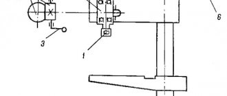
Kinematic diagram of screw-cutting lathe 16B20P
Kinematic diagram of a screw-cutting lathe 16B20p
The kinematic diagram is given to understand the connections and interactions of the main elements of the machine. The numbers of teeth (g) of the gears are indicated on the callouts (the asterisk indicates the number of starts of the worm).
The number I indicates a support with mechanical movement of the cutting slide
Movement is transmitted to the spindle in the following sequence:
- Two-speed electric motor 695 / 1400 rpm. Motor speed is selected using buttons
- Flat drive gearbox
- 6 speed gearbox
- Flat drive to spindle headstock
Setting the spindle speed in the spindle head is done by handle 1, which moves blocks 18-19-21-25-26.
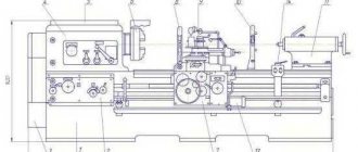
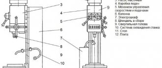
Structural diagram
The passport of the screw-cutting lathe 16b20p-061 describes its design. For rigidity, the machine bed is box-shaped and mounted on a base. The frame has ground guides that are hardened. Chips accumulate in a special cavity in the base. There is also an open container for coolant.
The precision bearings on which the machine spindle rests are not adjustable. At the output end of the spindle there is a flange with a fixed 3-jaw chuck.
The input end of the spindle, through a replaceable set of gears and a drive shaft or screw, transmits rotation to the feed box. It moves the support with the tool holder during turning of workpieces or making threads.
There are scales with sights on the caliper. They facilitate visual control of the movement of the slide during the cutting process. The tool holder securely fixes four cutters.
The apron is equipped with end stops with switches for confident stopping of the caliper feed mechanism. There are other locks and cutting zone guards available to guarantee safe operation of the machine.
When using a 16b20p lathe, it is important to monitor its condition - general and main structural elements. This greatly affects the accuracy of the operations performed and the surface quality of the parts. The guides of the caliper and frame require special attention.
Electrical diagram
The electrical circuit of the 16b20p-070 lathe is necessary for correct power connection when starting up the equipment, its operation and repair.
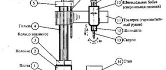
Description of the design of the screw-cutting lathe 16B20P
bed
The machine bed is cast; a rapid-speed electric motor is installed in a niche at the right end. The bed is installed on two hollow pedestals. The left one houses the main drive electric motor, the right one houses the electric cooling pump with an emulsion tank and the electric lubrication pump with a tank.
Front (spindle) headstock of screw-cutting lathe 16B20P
The position of the spindle axis relative to the frame guides is adjusted using set screws.
The spindle head contains:
- Pitch increasing link with gear ratios 1:1, 1:4, 1:16
- Spindle unit
- Gear mechanism for cutting right-hand and left-hand threads
The spindle assembly is mounted on special cone-roller bearings of the Gamet type (Gamet Bearings is an English manufacturer of precision bearings for equipment).
The gearbox for 6 spindle revolutions is removed from the spindle head and is mounted inside the left cabinet of the machine.
The gearbox contains:
- Gear mechanism (reducer)
- Starting and braking electromagnetic clutches
- Selective gearbox control mechanism
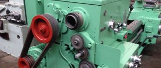
Main movement mechanism of screw-cutting lathe 16B20p
Gearbox
The feed box is mounted on the left side of the frame.
The feed box mechanism with replaceable guitar gears makes it possible to cut the entire main series of threads provided for by GOST.
Using the pitch increasing link, you can obtain threads with a pitch increased by 4 and 16 times
When specially tuning a guitar, small threads are cut in increments of 0.2 mm.
Feed selection is made by three handles mounted on the box.
- The left handle (6) selects a thread from the main row
- The right handle (7) moves the gear wheels of the multiplying mechanism
- The middle handle (5) selects the type of threads and work
An overrunning clutch is mounted on the right side of the box to obtain accelerated movements of the carriage and caliper.
Feed mechanism of screw-cutting lathe 16B20p
Setting up a 16B20p machine for cutting threads (table of threads)
Apron
The apron is equipped with four fine-toothed couplings that provide forward and reverse movement of the carriage and support in forward and reverse directions
The movements of the carriage and the lower part of the support are controlled by a mnemonic handle.
When working against stops or accidental overloads, the safety device of the apron, directly acting on the control mechanism, moves the fine-toothed clutches to the neutral position.
The ball locking device prevents the simultaneous activation of the uterine nut and longitudinal and transverse movements.
Caliper
The cross-design support has manual and mechanical longitudinal movement along the frame guides (carriage) and transverse movement along the carriage guides.
The upper support with a tool holder also has mechanical movement for turning short cones (the length of the cone generatrix is no more than 140 mm.
Electrical circuit diagram of a 16K20P screw-cutting lathe.
The electrical circuit diagram of the universal screw-cutting lathe 16K20P is shown in the following figure:
You can download a free electrical circuit diagram of a 16K20P screw-cutting lathe with specifications and in excellent quality from the link below:
the 16K20P screw-cutting lathe is shown in the following figure:
You can download for free this version of the electrical circuit diagram of a 16K20P screw-cutting lathe with specifications and in excellent quality from the link below:
Technical characteristics of the lathe 16B20P
| Parameter name | 16B20P | 16K20P |
| Basic machine parameters | ||
| Accuracy class according to GOST 8-82 | P | P |
| The largest diameter of the workpiece installed above the bed, mm | 400 | 400 |
| Height of the center axis above the flat guides of the frame, mm | 215 | 215 |
| The largest diameter of the workpiece processed above the support, mm | 220 | 220 |
| Maximum length of the part installed in the centers (RMC), mm | 1000 | 710, 1000 |
| The greatest distance from the axis of the centers to the edge of the tool holder, mm | 225 | 225 |
| The largest diameter of the drill when drilling steel parts, mm | 25 | |
| The largest mass of the part processed in the centers, kg | 460..1300 | |
| Maximum mass of the part processed in the chuck, kg | 200 | |
| Spindle | ||
| Spindle hole diameter, mm | 52 | 52 |
| The largest diameter of the rod passing through the hole in the spindle, mm | 50 | 50 |
| Spindle rotation speed in the forward direction (depending on the set of main motor pulleys), rpm | 16..1600 12,5..1250 100..2000 | 12,5..1600 |
| Spindle rotation speed in reverse direction, rpm | 19..1900 | |
| Number of forward spindle speeds | 22 | 22 |
| Number of spindle reverse speeds | 11 | |
| Spindle end according to GOST 12593-72 | 6K | 6K |
| Tapered spindle bore according to GOST 2847-67 | Morse 6 | Morse 6 |
| Spindle flange diameter, mm | 170 | 170 |
| Maximum torque on the spindle, Nm | 1000 | |
| Caliper. Submissions | ||
| Maximum length of longitudinal movement, mm | 930 | 645, 935 |
| Maximum length of transverse movement, mm | 250 | 300 |
| Speed of fast longitudinal movements, m/min | 4,0 | 3,8 |
| Speed of fast transverse movements, m/min | 2,0 | 1,9 |
| Maximum permissible speed of movement when working on stops, mm/min | 250 | |
| Minimum permissible speed of movement of the carriage (support), mm/min | 10 | |
| Price for dividing the longitudinal movement dial, mm | 1 | 1 |
| Transverse movement dial division price, mm | 0,05 | 0,05 |
| Longitudinal feed range, mm/rev | 0,05..2,8 | 0,05..2,8 |
| Transverse feed range, mm/rev | 0,025..1,4 | 0,025..1,4 |
| Number of feeds longitudinal/transverse | 22/24 | 22/24 |
| Limits of metric thread pitches, mm | 0,5..112 | 0,5..112 |
| Limits of pitches of inch threads, threads/inch | 56..0,25 | 56..0,5 |
| Limits of modular thread pitches, module | 0,5..112 | 0,5..112 |
| Limits of pitch thread pitches, diametric pitch | 56..0,25 | 56..0,5 |
| The greatest force allowed by the feed mechanism on the cutter is longitudinal, N | 5884 | |
| The greatest force allowed by the feed mechanism on the cutter is transverse, N | 3530 | |
| Cutting slide | ||
| Maximum length of movement of the cutting slide, mm | 150 | 150 |
| Movement of the cutting slide by one division of the dial, mm | 0,05 | 0,05 |
| Scale of rotation angle of the cutting slide, deg | ±90° | ±90° |
| Scale division of the tool slide rotation scale, deg | 1° | 1° |
| The largest cross-section of the cutter holder, mm | 25 x 25 | 25 x 25 |
| Height from the supporting surface of the cutter to the axis of the centers (cutter height), mm | 25 | 25 |
| Number of cutters in the cutting head | 4 | 4 |
| Tailstock | ||
| Quill diameter, mm | ||
| Tailstock quill hole cone according to GOST 2847-67 | Morse 5 | Morse 5 |
| Maximum movement of the quill, mm | 200 | 150 |
| Movement of the quill by one division of the dial, mm | 5 | 0,1 |
| The amount of lateral displacement of the headstock body, mm | ±15 | ±15 |
| Electrical equipment | ||
| Main drive electric motor, kW | 4,1/ 6,6 | 11 |
| Electric motor for fast movement drive, kW | 0,6 | 0,12 |
| Lubrication pump drive electric motor, kW | 0,27 | |
| Coolant pump electric motor, kW | 0,125 | 0,125 |
| Dimensions and weight of the machine | ||
| Machine dimensions (length width height) RMC=1000, mm | 2595 x 1405 x 1115 | 2795 x 1190 x 1500 |
| Machine weight, kg | 2050 | 3010 |
* the price of a restored machine is indicated (since these machine models are no longer produced)