The 2N125 vertical drilling machine is used in enterprises with single and small-scale production and is designed for drilling, reaming, countersinking, countersinking, reaming and trimming ends with knives. The presence of a mechanical spindle feed on the machine, with manual control of work cycles, allows the processing of parts in a wide range of sizes from various materials using tools from high-carbon and high-speed steels and hard alloys. An electric device for reversing the main movement motor installed on the machine allows thread cutting using machine taps with manual spindle feed.
Information about the manufacturer of the vertical drilling machine 2N125
The manufacturer of vertical drilling machines models 2N125, 2N135, 2N150, 2G175 is the Sterlitamak Machine Tool Plant , founded in 1941.
The history of the Sterlitamak Machine Tool Plant begins on July 3, 1941, when the evacuation of the Odessa Machine Tool Plant to the city of Sterlitamak began.
Already on October 11, 1941, the Sterlitamak Machine Tool Plant began producing special modular machines for the defense industry.
Currently, the plant produces metalworking equipment, including CNC lathes and milling machines, multifunctional machining centers.
Products of the Sterlitamak Machine Tool Plant
- 2135
— universal vertical drilling machine, Ø 35 - 2A125
- universal vertical drilling machine, Ø 25 - 2A135
- universal vertical drilling machine, Ø 35 - 2A150
- universal vertical drilling machine, Ø 50 - 2G175
- universal vertical drilling machine, Ø 75 - 2N125
- universal vertical drilling machine, Ø 25 - 2N135
- universal vertical drilling machine, Ø 35 - 2N150
- universal vertical drilling machine, Ø 50 - 2R135F2
- CNC vertical drilling machine, Ø 35 - 2С50
- universal vertical drilling machine, Ø 50 - 2S125, 2S125-1 (2S125-01), 2S125-04
- universal vertical drilling machine, Ø 25 - 2S132, 2S132K
- universal vertical drilling machine, Ø 32 - 2С150ПМФ4
- vertical drilling-milling-boring machine with CNC and ASI, 500 x 1000 - 2С550А
– radial drilling machine, Ø 36 - 400V
- vertical drilling-milling-boring machine with CNC and ASI, 400 x 900 - 500V (STC F55)
- vertical milling center, 630 x 1200 - SF-16, SF-16-02, SF-16-05
- tabletop milling and drilling machine, Ø 16 - SRB50
– radial drilling machine, Ø 3..50
What is a machine model 2N125
Fully justifying its versatility, the 2N125 device allows you to effectively perform a whole list of technological operations:
- drilling and reaming holes;
- deployment;
- countersinking;
- internal thread cutting.
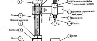
Location of the main parts of the machine
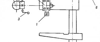
This vertical drilling machine is equipped with only one spindle unit, which makes the design of the equipment simple and reliable. On the modern market there are a number of modifications of this machine with several drilling heads, into which various tools can be installed in order to process parts with higher productivity.
Spindle assembly structure: 1 – bearing adjustment nut; 2 – spindle; 3 – sleeve; 4 – lever
The technical characteristics of the unit in question are optimally suited for use in small-scale production. Vertical drilling machines 2N125 demonstrate themselves best when processing parts of medium thickness, made of steel of not very high strength. According to the passport, the machine in question can use drills whose diameter does not exceed 25 mm. Modifications of the model are distinguished by expanded characteristics: they can work with drills with a diameter of up to 35 mm.
Despite the fact that mass production of the 2N125 vertical drilling machine was launched in the middle of the last century, it can still be found in the equipment of many manufacturing enterprises. The main reason for the high reliability of the device is the kinematic circuit, which, due to its characteristics, is able to work effectively even in the most difficult conditions. The simplicity of the kinematic diagram also ensures that in the event of a breakdown, such equipment can be quickly repaired using a standard set of tools.
Kinematic diagram and rotation graphs of the main drive of the machine: a) 2N125; b) 2N135 (click to enlarge)
Of course, the vertical drilling machine model 2N125 does not have the same compact dimensions and ease of use as many modern devices, but these minor shortcomings are compensated by its high reliability and affordable price.
2N125 universal single-spindle vertical drilling machine. Purpose and scope
Vertical drilling machine 2N125 (TU 2-024-4645-79) replaced the outdated model 2A125
.
Vertical drilling machine 2N125 , with a nominal drilling diameter of 25 mm, is used in enterprises with single and small-scale production and is designed to perform the following operations: drilling, reaming, countersinking, countersinking, reaming, threading and trimming ends with knives.
2N125 drilling machine allows processing of parts in a wide range of sizes from various materials using tools from high-carbon and high-speed steels and hard alloys.
Drilling operations on the 2n125 machine
Operating principle and design features of the machine
2N125 machine belongs to the design range of medium-sized vertical drilling machines (2N118, 2N125, 2N125L, 2N135, 2N150, 2G175) with a nominal drilling diameter of 18, 25, 35, 50 and 75 mm, respectively. Compared to previously produced machines (with index A), the new range of machines have a more convenient location of the gearbox and feed control handles, better appearance, simpler technology for assembling and machining a number of critical parts, and a more advanced lubrication system. The aggregate layout and the ability to automate the cycle ensure the creation of special machines based on them.
The limits of spindle speeds and feeds make it possible to process various types of holes using rational cutting conditions.
The presence of mechanical spindle feed on machines, with manual control of work cycles.
Allows processing of parts in a wide range of sizes from various materials using tools from high-carbon and high-speed steels and hard alloys.
Vertical drilling machines 2N125 are equipped with a device for reversing the main movement electric motor, which allows them to cut threads with machine taps while manually feeding the spindle.
Placement category 4 according to GOST 15150-69.
Developer: Odessa Special Design Bureau of Special Machine Tools.
Chronology of the plant's production of vertical drilling machines 2125 series with drilling diameters up to 25 mm:
- 2125 - the first model of a series of vertical drilling machines, produced from 1945 to 1950.
- 2A125, 2A125A, 2A125K - the next models in the series, produced from 1950 to 1965.
- 2N125, 2N125A, 2N125K, 2N125F2 - the most popular and widespread model of the series, produced from 1965 to the early 90s
- 2S125, 2S125-01, 2S125-04 are the latest models in the series. Discontinued in 2014
Modifications of drilling machines 2N125
To process holes of different diameters, basic vertical drilling machines are used: 2H125 .
The last two digits of each model number indicate the largest hole diameter in mm that can be drilled on this machine in 45 steel workpieces. Based on the above basic machine models, the following modified models have been created:
- 2N125A - vertical drilling machines with automated control (control is carried out using pre-configured cams and buttons);
- 2N125K - coordinate vertical drilling machines with a cross table;
- 2N125S - special single-position vertical drilling machines with a flanged quill used for fastening multi-spindle heads;
- 2N125N - multi-position drilling machines designed for installing multi-spindle heads and rotary tables;
- 2N125F2 - drilling machines with CNC, cross table and turret head, etc.
Analogues of vertical drilling machines 2N125, currently produced:
- 2T125, 2T140, 2T150 - manufacturer: Gomel Machine Unit Plant
- 2AS132, 2AS132-01 - manufacturer: Astrakhan Machine Tool Plant
- 2L125, 2L132, 2L135, LS25, LS35 - manufacturer: Lipetsk Machine Tool Enterprise (PJSC STP-LSP)
- MN25L, MN25N-01 - manufacturer: Molodechno Machine Tool Plant
Where is it used?
Like the famous 2N135 unit, the 2N125 model is designed for low production volumes. The equipment is ideal for installation in a small small-scale workshop, as well as for work in domestic conditions. The 2n125 drilling machine has a nominal drilling diameter of 25 millimeters. With its help, you can not only drill and ream holes, but also perform a number of other operations.
At the same time, the machine operator can independently select the speed and spindle feed mode, which allows optimal use of equipment resources to perform a specific task. The machine is capable of working with a wide variety of holes and materials as efficiently as possible, which is also worth noting as an advantage of the model. The equipment belongs to placement category 4 in accordance with GOST 15150-69.
Since this model has been around for decades, it would be crazy if such a popular technique had not undergone a single modification throughout its existence. In this regard, the manufacturer took care of satisfying the most specific needs of the craftsman, offering several possible variations of the 2n125 drilling machine
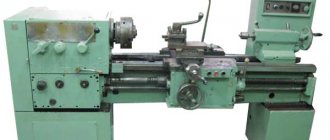
This is interesting: Lathes
Dimensions of the working space of the drilling machine 2N125
Drawing of the working space of the drilling machine 2N125
| Machine model | Morse cone | A | B | IN | D | D1 | M |
| 2N125 | 3 | 250 | 700 | 60 | 45 | 23,825 | 400 |
| 2N135 | 4 | 300 | 750 | 30 | 60 | 31,267 | 450 |
| 2N150 | 5 | 350 | 800 | 0 | 80 | 44,399 | 500 |
General view of the drilling machine 2N125
Photo of drilling machine 2N125
Photo of drilling machine 2N125
Photo of drilling machine 2N125
Photo of drilling machine 2N125
Photo of drilling machine 2N125
Scope of application and capabilities
The main area of application of the 2n125 drilling machine is production in small batches. The unit is designed for processing products that are thin and made of medium-strength steel.
The maximum permissible diameter of drills intended for the machine is 25 mm. This provision is provided for by the device passport. Modern machine models provide craftsmen with the opportunity to use drills with an even larger diameter, reaching 35 mm.
The design of the unit has the following features:
- the presence of a reversible mechanism designed for more precise threading;
- the principle of manual control, in which the feed is performed manually;
- the ability to change the operating mode of the machine without stopping the spindle;
- high stability of the structure due to the uniform placement of machine elements and its large mass.
Manual control of the device is based on its vertical movement due to the flywheel handle, which requires periodic lubrication.
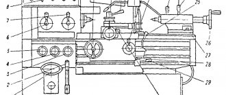
Location of the main parts of the drilling machine 2N125
Location of the main components of the drilling machine 2N125
Designation of the main parts of the drilling machine 2N125
- Drilling machine drive - 2Н125.21.000
- Machine gearbox - 2Н125.20.000
- Piston oil pump - 2N125.24.000 for machine 2N125
- Piston oil pump - 2N135.24.000
- Feed box - 2Н125.30.000
- Column, table, slab - 2N125.10.000
- Speed and feed control mechanism - 2Н125.25.000
- Electrical cabinet - 2N125.72.000
- Electrical equipment - 2N125.94.000
- Spindle assembly - 2Н125.50.000
- Machine cooling system - 2N125.80.000
- Drilling head - 2Н125.40.000
Location of controls for drilling machine 2N125
Location of controls for drilling machine 2N125
List of controls for drilling machine 2N125
- Table - “Filling” coolant
- Sign - "Drain"
- Cooling valve
- + 19 Bolts for adjusting the table wedge and drilling head
- Table moving handle
- Table clamp and drill head screws
- Sign - “Grounding”
- Input switch
- Label - “Main Switch”
- Signal button MACHINE ON
- Right spindle rotation button
- Spindle left rotation button
- Button for turning on the swinging movement of the spindle when switching speeds and feeds
- Gear shift knob
- STOP button
- Table - “Rotation speed”
- Sign - “Change speed only when stopping”
- Table clamp and drill head screws
- +4 Bolts for adjusting the table wedge and drill head
- Table - “Feed, mm per revolution”
- Feed shift knob
- Manual feed button
- Feed wheel
- Limb for counting the processing depth
- Light switch
- Label - “Cooling”
- Cooling pump switch
- Cam for adjusting the processing depth
- Cam for adjusting the depth of the thread being cut
- Lever for automatic reversal of the main drive when the specified depth of the thread being cut is reached
- Lever to turn off the mechanical feed when the specified processing depth is reached
- Square for manual movement of the drill head
List of graphic symbols indicated on the plates of the 2N135 drilling machine
List of graphic symbols on the plates of the drilling machine 2n135
Operating procedure of the drilling machine 2N135
Mechanical spindle feed
Setting up the machine for normal operation with a mechanical spindle feed consists of installing the table and drilling head in the positions required for operation, clamping them on the column, and setting the required rotation speeds and spindle feeds.
When setting up the machine to operate with manual spindle feed, the knurled cap located in the center of the cross steering wheel should be pressed away from you until it stops.
Turning off the spindle feed at a given depth
When setting up work with turning off the spindle feed at a given depth, the following sequence must be observed:
- install the tool in the spindle;
- secure the workpiece on the table;
- lower the spindle until the tool stops in the part;
- Use a screw to press out and install the dial of the drilling head so that opposite the pointer there is a number corresponding to the depth of processing, taking into account the sharpening angle of the tool.
- Secure the dial. Secure the cam with the letter “P” so that its mark coincides with the corresponding mark on the dial.
After turning on the rotation and feed of the spindle, processing of the part begins. When the desired machining depth is reached, the spindle feed will stop and the spindle will continue to rotate. To stop it, you need to press the STOP button.
Setting up a machine for thread cutting
When setting up a machine for thread cutting with spindle reversal at a certain depth, the following sequence must be observed:
- install the chuck with the tap in the spindle;
- install the workpiece on the machine table;
- lower the spindle until the tool stops in the part;
- Set the dial on the drilling head so that opposite the pointer there is a number corresponding to the processing depth. Align the cam mark “P” with the corresponding mark on the dial and secure the cam.
- Turn off mechanical feed. After turning on the spindle, manually insert the tap into the hole. After 2-3 spindle revolutions, there is no need for manual feed.
- When the specified cutting depth is reached, the spindle is automatically reversed and the tap exits the hole. In order for the spindle to resume right rotation, you need to press the corresponding button.
After installation, lubrication and connection of the machine to the electrical network, no additional adjustments are required. During operation, the initial adjustment may be disrupted.
Operating instructions
The safety clutch of the feed mechanism is adjusted according to the axial force on the spindle by 15% more than the permissible one. To adjust the coupling, it is necessary to remove the right upper cover of the drilling head and use the nut on the worm to decrease or increase the spring tension.
The table guides are adjusted by screws on the right side of the table. The table is clamped using a square screw located on the right side of the table and a table lifting handle.
The guides of the drilling head are adjusted with screws located on the right side surface of the guides; the head itself is clamped with a screw with a square on the same side using the table lift handle.
To tighten the counterweight spring, you need to unscrew the plug at the bottom of the drilling head, drain the oil from the reservoir, and turn the screw to tighten the spring.
For the convenience of clamping the workpiece in the machine vice supplied with the machine, you can use handle 5 (see Fig. 4).
How the gearbox works
The gearbox components are quite easy to assemble. They are lubricated by a special gear pump, which is located in the feed box.
The function of the machine drive is to provide communication between the gearbox and the shaft of the electric motor. The drive has the form of a housing on which the electric motor is mounted.
A half-coupling is attached to the engine shaft, transmitting rotation to the half-coupling gear, which engages with the primary gear of the gearbox. The feed box is a three-shaft device. The device is housed in a special molded housing. The first shaft of the box is equipped with a movable gear block. The unit carries out three spindle feeds in automatic mode.
The box is equipped with a safety clutch. Its function is reduced to turning off the feed in mechanical mode when the required depth of machining of the part has been reached. The coupling itself is located on the input shaft of the drilling head.
The drilling head is a cast iron casting in which the main working elements of the machine are located: the feed and speed box, the feed mechanism with the spindle. If the assembly of the feed and speed box together with the spindle is carried out separately, then the feed mechanism is already included in the drilling head.
The spindle is made on ball bearings. They are located in its sleeve. The sleeve is able to move along the axis thanks to a rack and pinion transmission.
The vice is mounted in the workbench bracket. They rotate well and can be installed at any angle relative to the drill.
The electrical equipment of the machine is represented by a squirrel-cage asynchronous motor.
Kinematic diagram of the drilling machine 2N125
Kinematic diagram of the drilling machine 2N125
Bearing layout for drilling machine 2N125
Bearing layout for drilling machine 2N125
Description of the main components of the drilling machine 2N125
Gearbox of drilling machine 2N125
Drawing of the gearbox of the drilling machine 2N125
Gearbox and drive. The gearbox communicates to the spindle 12 different rotation speeds using movable blocks 5 (Fig. 7), 7, 8. The gearbox shaft supports are placed in two plates - upper and lower 4, fastened together by four ties 6. The gearbox is driven into rotation by a vertically located by an electric motor through an elastic coupling 10 and a gear 9. The last shaft 2 of the box - the sleeve - has a splined hole through which rotation is transmitted.
Through gear pair 3, rotation is transmitted to the feed box.
The gearbox, as well as all assembly units of the drilling head, is lubricated from a plunger pump mounted on the lower plate 4. The operation of the pump is controlled by a special oil indicator on the frontal part of the sub-motor plate.
Mechanism for controlling speeds and feeds of the drilling machine 2N125
Mechanism for controlling speeds and feeds of the drilling machine 2N125
Mechanism for switching speeds and feeds of a drilling machine 2N125
Mechanism for switching speeds and feeds of a drilling machine 2N125
Mechanism for switching speeds and feeds . The gears are switched by handle 2 (Fig. 8), which has four positions around the circumference and three along the axis, the feeds are switched by handle 3, which has three positions along the circumference for machines of models 2N135 and four for 2N150, and three positions along the axis. The handles are located on the front side of the drilling head. The countdown of switched on speeds and feeds is carried out according to plates 1 and 4.
Feed box for drilling machine 2N125
Drawing of the feed box of the drilling machine 2N125
Gearbox. The mechanism is mounted in a separate housing and installed in the drilling head. By moving two triple gear blocks, nine different feeds are carried out on the 2N125, 2N135 machines and twelve feeds on the 2N150 machine. On the 2N125 and 2N135 machines, the feed boxes differ only in the drive, which consists of gears 1 on the 2N125 machine (Fig. 9), and on gears 2, 3 on the 2N125, 2N135 machines, respectively. The feed box is mounted in the bore of the upper support of the worm of the feed mechanism. On the last shaft of the box there is a clutch 4, which transmits rotation to the worm.
Drilling head of machine 2N125
Drawing of the drilling head of the drilling machine 2N125
The drilling head is a box-section casting in which all the main assembly units of the machine are mounted: speed box, feed box, spindle, feed mechanism, spindle counterweight and speed and feed switching mechanism.
The feed mechanism , consisting of a worm gear, a horizontal shaft with a rack and pinion gear, a dial, cam and ratchet overrunning clutches, and a steering wheel, is an integral part of the drilling head.
The feed mechanism is driven from the feed box and is designed to perform the following operations:
- manually bringing the tool to the part;
- turning on the working feed;
- manual feed advance;
- turning off the working feed;
- manual spindle retraction upward;
- manual feed used in thread cutting.
The principle of operation of the feed mechanism is as follows: when the steering wheel 14 (Fig. 10) rotates, the cam clutch 8 turns toward itself, which, through the half-coupling cage 7, rotates the rack and pinion gear shaft 3, and the spindle is fed manually. When the tool approaches the part, a torque arises on the gear shaft 3, which cannot be transmitted by the teeth of the cam coupling 8, and the half-coupling cage 7 moves along the shaft until the ends of the cams of parts 7 and 8 are facing each other. At this moment, the cam clutch 8 rotates relative to the gear shaft 3 at an angle of 20°, which is limited by a groove in part 8 and a pin 10. On the holder - half-coupling 7 sits a double-sided ratchet disk 6, connected to the half-coupling by pawls 13. When moving the holder-half-coupling 7 the teeth of the disk 6 engage with the teeth of the disk, which is integral with the worm wheel 5. As a result, rotation from the worm is transmitted to the rack and pinion gear and the spindle is mechanically fed. With further rotation of the steering wheel 14 with the feed switched on, the pawls 13, sitting in the half-coupling cage 7, slip over the teeth of the inner side of the disk 6; There is a manual advance of the mechanical feed.
When the feed is manually turned on by the steering wheel 14 (after turning it towards itself at an angle of 20°), the tooth of the coupling 8 stands against the cavity of the half-coupling cage 7. Due to the axial force and the special spring 12, the half-coupling cage 7 moves to the right and disengages the toothed disks 5 and 6; mechanical feed stops.
The feed mechanism allows manual spindle feed. To do this, it is necessary to turn off the mechanical feed with the steering wheel 14 and move the cap 9 along the axis of the gear shaft 3 away from you. In this case, pin II transmits torque from the cam clutch 8 to the horizontal shaft. A dial 4 is mounted on the left wall of the drilling head for visually measuring the processing depth and adjusting the cams.
To manually move the drilling head along the column guides, there is a mechanism that consists of a worm pair 2 and a rack pair I. To protect the feed mechanism from breakage, there is a safety clutch 15. A nut 16 and a screw 17 are used to regulate the spring counterweight.
Machine design features
Description of the unit design includes:
- gearbox;
- drive unit;
- feed box;
- drill head;
- spindle;
- rotary vice;
- electrical equipment.
Operating principle of the gearbox:
- communication of revolutions to the spindle using two movable triples;
- the box shaft supports are located in the upper and lower plates, held together by 4 ties;
- The electric motor drives the gearbox through a gear train and clutch;
- the last shaft of the box has the form of a hollow sleeve, its splined hole transmits rotation to the machine spindle;
- The gears of the box are switched using a handle.
This is interesting: Homemade CNC milling machine: assemble it yourself
Adjusting the drilling machine 2N125
Spindle assembly for vertical drilling machine 2N125
Spindle assembly for vertical drilling machine 2N125
Spindle 2 (Fig. 11) is mounted on 4 ball bearings. The axial feed force is perceived by the lower thrust bearing, and the tool knockout force is perceived by the upper one. The bearings are located in sleeve 3, which moves along the axis using a rack and pinion pair. The spindle bearings are adjusted using nut 1.
To knock out the tool, use a special device on the spindle head. Knockout occurs when the spindle is lifted by the steering wheel. The holder of the device rests against the body of the drilling head, and the lever 4 rotates around its axis; knocks out the tool.
The spindle of the 2N125 drilling machine is mounted on 4 bearings:
- 21. Upper bearing No. 5-206 , single-row radial ball, 30x62x16 mm, 5 accuracy class
- 20. Bearing No. 5-8106 , thrust ball, 30x47x11 mm, 5th accuracy class
- 24. Bearing No. 5-8306 , thrust ball, 30x60x21 mm, 5th accuracy class
- 25. Lower bearing No. 5-206 , single-row radial ball, 50x80x16 mm, 5 accuracy class
When assembling the machine during the repair process, it is necessary to observe conditions that affect the accuracy of its operation.
Thus, the gap between the guide bushings of the drill head and the quill of the spindle assembly should be no more than 0.01 mm.
When installing the drilling head and table on the column guides, the 0.03 mm probe should not pass into the joint, and all the requirements of GOST 7599-73 section 4 must be met.
The spindle thrust bearings are also subject to adjustment .
To adjust the spindle thrust bearing you must:
- unscrew the plug on the front part of the drilling head of the 2N125 machine or the cover on 2N135 and 2N150;
- install the spindle so that the stopper in the nut is aligned with the hole;
- release the stopper and, turning the spindle, align the hole in the nut with the hole in the drilling head;
- Having inserted a cylindrical rod into the hole of the nut, turn the spindle counterclockwise until the axial play is eliminated and tighten the nut stopper.
Technical characteristics of bearing No. 5-206
Bearing No. 5-206 - single-row radial ball, 50x80x16 mm
This type of bearing is used everywhere in all branches of industry and agriculture. In terms of the number of units sold, this bearing is only inferior to exactly the same one, but one size smaller - 205. Basically, such a bearing is bought as a closed type - 180206, and it is this bearing that is produced in large volumes at bearing factories. The design - radial ball - is designed to absorb radial loads and, to a very small extent, axial loads.
In addition to these two modifications, there are 80206 (closed on both sides with metal washers), 60206 (closed on one side) and 50206 - with a groove along the outer ring for a retaining ring (the latter type is used quite rarely). Bearings are produced mainly of class 6 precision, they are intended for the mass consumer. For the needs of individual industries, various modifications are produced with additional operating requirements (requirements for noise, accuracy, resistance to temperature or chemical influences), increased load capacity (indicated by the letter A to the right of the main designation).
The main manufacturing plants in our country are JSC SPZ (Saratov, 3 GPP), VBF (Vologda, 23 GPP), LLC SPZ-4 (Samara) and 2 GPP (Moscow). The last two factories assemble bearings from Chinese components, produced with quality control from normal metal (unlike brands such as CRAFT, SZPK, hb and others), which makes them lower in price with decent performance characteristics. Bearings for the mass consumer are produced in accordance with GOST 520-2002, special modifications are made in accordance with TU and ETU and are supplied directly from one plant to another, bypassing the dealer network.
You can buy bearings of this type at minimal prices from official dealers of factories.
The approximate price of the product depends very much on the manufacturer and ranges from 34 - 35 (China) to 280 - 300 rubles (SKF). Bearings with protective washers and plugs are slightly more expensive than open ones. Russian bearings are closer in price to Chinese ones, but in quality they are much better.
The bearing has the following characteristics (bearing 6-180206 - closed on both sides with rubber seals, basic design, cage made of ShKh-15 steel):
Imported bearings of this standard size are designated as 6206 /Рх (where x is the accuracy class of the manufactured bearing and varies from 2 to 6) with additional designations of protective washers and plugs as Z, ZZ or 2RS. For example, 6206 2RS is the designation for bearing 180206 adopted by the manufacturer FAG.
Applicability of bearing 180206 (closed, analogue - 6206 2RS) in domestic automotive and agricultural equipment:
Dimensions and characteristics of bearing 206 (50206, 60206, 80206, 180206, 6206)
- Inner diameter (d): – 30 mm;
- Outer diameter (D): – 62 mm;
- Width (height) (H): – 16 mm;
- Weight: – 0.21 kg;
- Ball diameter: – 9.525 mm;
- Number of balls in the bearing: – 9 pcs.;
- Dynamic load capacity: – 25.35 kN;
- Rated speed: – 7500 rpm.
Diagram of bearing 206 of drilling machine 2N125
Technical characteristics of bearing No. 8306
Bearing 8306 is a single-row thrust ball bearing consisting of three parts - two rings (the diameter of one of them is 1 mm less than the one that is mounted directly on the shaft) and a cage on which the rolling elements are located.
Used in industrial equipment in units with axial load. This is a thrust ball bearing (they are easy to distinguish by number: the fourth number from the end is 8), single, of the basic design. It is used in components of machines and mechanisms that are subject to axial loads. The stopper consists of two flat rings (which differ in internal diameter by approximately 1 mm) and a number of balls on a stamped steel or brass separator.
This type is produced at 2 gas processing plants (Moscow), SPZ-4 (Samara), 20 gas processing plants, or KZUP (Kursk). A modification with a brass separator and the sixth class of accuracy - 6-8306 NLSh1 - is produced in Vologda at 23 GPP (VBF brand).
In automotive engineering, it completes special equipment for the ZIL 137 truck.
Imported bearings 8306 (as well as Moscow and Vologda) are marked according to the international designation system - 51306.
Dimensions and characteristics of bearing 8306 (51306)
- Inner diameter (d): – 30 mm;
- Outer diameter (D): – 60 mm;
- Width (height) (H): – 21 mm;
- Weight: – 0.268 kg;
- Ball diameter: – 11.112 mm;
- Number of balls in the bearing: – 11 pcs.;
- Dynamic load capacity: – 40.3 kN;
- Static load capacity: – 66.5 kN;
- Rated rotation speed: – 3800 rpm.
Diagram of bearing 8306 (51306) drilling machine 2N125
Photo of bearing 8306 (51306)
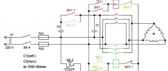
Electrical equipment and electrical circuit of the drilling machine 2N125
Electrical diagram of drilling machine 2N125
List of elements for the electrical circuit of the drilling machine 2N125
The electrical circuit diagram is the same for the entire series of machines 2n125, 2n135, 2n150. However, the components included in the electrical circuit have different parameters due to the fact that the models have main engines of different power (2n125 - 2.2 kW, 2n135 - 4.0 kW, 2n150 - 7.5 kW)
Thus, all elements of the electrical circuit associated with the main engines have different parameters on different machine models, see Table 2.
Table of variable data for the electrical circuit of the drilling machine 2N125
Brief characteristics of electrical equipment
The electrical equipment of the machines includes a three-phase squirrel-cage asynchronous electric motor for rotation and working feed of the spindle, an electric cooling pump, and electrical control equipment.
The AC voltage values can be as follows:
- power circuit 3 ~ 50 Hz, 220, 380, 400, 415, 440 and 500 V;
- control circuit ~ 110 V;
- local lighting circuit ~ 24 V;
- alarm circuit ~ 5 V.
The power circuit voltage is determined by the customer.
Description of the operation of the electrical circuit of the machine
Initial Startup Information
During the initial start-up of the machine, it is necessary to free the magnetic starters from the wedges, check the reliability of the clamping of wires and grounding, and the integrity of the installation of electrical equipment by external inspection.
After inspection in the electrical control cabinet of the incoming automatic machine Q1, connect the machine to the workshop network, using buttons and switches, check the clear operation of the magnetic starters and relays, and the correct direction of rotation of the electric motor M1. The check must be done at idle speed.
Description of operating modes
By turning on the input circuit breaker Q1, voltage is supplied to the main and auxiliary circuits, and the H2 signal lamp on the remote control lights up. If cooling and lighting are required, the corresponding switches are placed in the ON position.
By pressing the S2 RIGHT button, the starter coil K1 receives power, the main contacts turn on the electric motor Ml for right rotation of the spindle. Through the block contacts K1, the starter K2 is turned on, which turns on the electric motor M2 and the delay relay K7.
When you press the S3 LEFT button, the starter K1, the electric motor Ml, and the relay K7 are turned off. After the discharge of capacitor C3, the contacts of relay K7 (28-26) close, and the starter K3 and the electric motor Ml are turned on for left-hand rotation of the spindle. Relay K7 turns on again.
With automatic reverse, these switches occur when microswitch S6 is activated from a cam mounted on the dial.
Stopping is carried out by pressing the S1 STOP button. In this case, starters K1 or K3, K2 are turned off, turning off electric motors M1, M2. Through relay contacts K7 (7-9), relay K6 is turned on, followed by starters K4 and K5. The windings of the electric motor Ml are connected via rectifier VI, V2 to transformer T1. Electrodynamic braking of the spindle occurs.
After the discharge of capacitors C1, C2, relay K6 is turned off, turning off starters K4, K5.
When switching speeds, if the gears do not engage, the rocking motion of the engine rotor Ml is used. By pressing the S4 ROCKING MOTION button, starter K4 is turned on, supplying reduced rectified voltage through phases IC2-IC3.
Through resistance R2, relay K6 is turned on with a delay, turning off starter K4 and turning on starter K5. In this case, the reduced voltage flows through the phases ICI-IC2. Such switchings provide swinging of the rotor, which makes it easier to change gears.
Instructions for using electrical equipment
It is necessary to periodically check the condition of the starting and relay equipment. Contacts of electrical devices must be cleaned of dust, dirt and carbon deposits.
When inspecting relay equipment, special attention should be paid to the reliability of the closing and opening of contact bridges.
The frequency of technical inspections of engines is set depending on production conditions, but not less than once every two months.
Information about interlocks, alarm system, protection and grounding
The input circuit breaker is equipped with a special lock that locks the input switch in the off state.
When the input switch is turned on, a special lamp with a white lens lights up on the remote control. Protection against short circuit currents is provided by a circuit breaker and fuses.
Overload protection of motors Ml, M2 is provided by thermal relays. Zero protection is provided by coils and contacts of electromagnetic starters.
The machine must be securely connected to the workshop grounding device.
From the grounding terminals of the electrical cabinet, protective circuits are routed to the motor housings and the control panel.
Techniques for drilling light alloys
Many types and grades of light alloys are characterized by lower cutting resistance than ferrous metals. Therefore, they are processed at increased cutting speeds with tools made of high-speed steels equipped with carbide alloys. When processing holes, for example in magnesium alloys (ML4, ML5, etc.), on drilling machines, it should be taken into account that the economical speed when using these tools is much higher than what drilling machines can provide. In addition, when processing magnesium alloys at high speeds, there is a danger of their spontaneous ignition.
Taking into account the specifics of processing light alloys, it is recommended to drill them, observing the following rules:
- 1. Holes in workpieces made of magnesium alloys must be drilled with drills made of carbon or alloy tool steels. On the front surface of the drill, make a chamfer with a rake angle equal to 5° (Fig. 87) and a width of 0.2..0.6 mm depending on the diameter of the drill (the wider the chamfer, the larger the diameter of the drill).
- 2. To reduce the axial cutting force and obtain crushed chips for the same drills, the jumper should be ground to a thickness of 0.08..1.0 drill diameter D; make the angle φ equal to 45°, the rear angle α ~ 15°.
- 3. Drills for drilling holes in duralumin alloys of grades D1, D16, etc. must have a chrome-plated cutting part. This prevents small metal particles from sticking to the drill, which complicate chip flow, increase the roughness of the machined surface and accelerate drill wear.
- 4. For drilling aluminum alloys, it is necessary to use drills with larger angles φ and ω than for drilling ferrous metals; the angle φ should be equal to 66..70°, the angle of inclination of the helical grooves ω is equal to 35..45°, the relief angle α = 8..10°.
Technical characteristics of the machine 2N125
| Parameter name | 2N125 | 2N135 | 2N150 |
| Basic machine parameters | |||
| The largest drilling diameter in steel is 45, mm | 25 | 35 | 50 |
| The smallest and largest distance from the end of the spindle to the table, mm | 60…700 | 30…750 | 0…800 |
| The smallest and largest distance from the end of the spindle to the plate, mm | 690…1060 | 700…1120 | 700…1250 |
| Distance from the axis of the vertical spindle to the rack guides (overhang), mm | 250 | 300 | 350 |
| Desktop | |||
| Maximum load on the table (center), kg | |||
| Dimensions of the working surface of the table, mm | 400 x 450 | 450 x 500 | 500 x 560 |
| Number of T-slots Dimensions of T-slots | 3 | 3 | 3 |
| Maximum vertical movement of the table (Z axis), mm | 270 | 300 | 360 |
| Table movement per one revolution of the handle, mm | |||
| Spindle | |||
| Maximum movement (installation) of the spindle head, mm | 170 | 170 | 250 |
| Maximum movement (stroke) of the spindle, mm | 200 | 250 | 300 |
| Spindle movement by one dial division, mm | 1,0 | 1,0 | 1,0 |
| Spindle movement per one revolution of the handwheel-handle, mm | 122,46 | 122,46 | 131,68 |
| Spindle speed, rpm | 45…2000 | 31,5…1400 | 22,4…1000 |
| Number of spindle speeds | 12 | 12 | 12 |
| Maximum permissible torque, Nm | 250 | 400 | 800 |
| Spindle taper | Morse 3 | Morse 4 | Morse 5 |
| Machine mechanics | |||
| Number of working feed stages | 9 | 9 | 12 |
| Limits of vertical working feeds per spindle revolution, mm | 0,1…1,6 | 0,1…1,6 | 0,05…2,24 |
| Cycle management | Manual | Manual | Manual |
| Maximum permissible feed force, kN | 9 | 15 | 23,5 |
| Dynamic spindle braking | Eat | Eat | Eat |
| Drive unit | |||
| Main motion drive electric motor, kW | 2,2 | 4,0 | 7,5 |
| Electric coolant pump Type | X14-22M | X14-22M | X14-22M |
| Machine dimensions | |||
| Machine dimensions, mm | 2350 x 785 x 915 | 2535 x 825 x 1030 | 2930 x 890 x 1355 |
| Machine weight, kg | 880 | 1200 | 1870 |
- Universal vertical drilling machines 2N125, 2N135, 2N150. Operating manual 2N125.00.000 RE, 1987
- Barun V.A. Working on drilling machines, 1963
- Vinnikov I.Z., Frenkel M.I. Driller, 1971
- Vinnikov I.Z. Drilling machines and work on them, 1988
- Loskutov V.V Drilling and boring machines, 1981
- Panov F.S. Working on CNC machines, 1984
- Popov V.M., Gladilina I.I. Driller, 1958
- Sysoev V.I. Handbook for a Young Driller, 1962
- Tepinkichiev V.K. Metal cutting machines, 1973
Bibliography:
Related Links. Additional Information
- Classification and main characteristics of drilling-milling-boring group of machines
- Selecting the right metalworking machine
- Machine repair technology
- Methodology for checking and testing drilling machines for accuracy and rigidity
- Directory of drilling machines
- Manufacturers of drilling machines in Russia
Home About the company News Articles Price list Contacts Reference information Interesting video KPO woodworking machines Manufacturers
Comparison with other models
2N125F2 is one of the most developed and advanced models of devices in this series. The main advantage of the unit is the presence of a numerically controlled mechanism. The device is equipped with a cross-type table and a turret spindle head.
Model 2Н125С is characterized by even greater versatility compared to the original machine. Such devices are equipped with spindles with several slots. Different drills are inserted into them, which expands the capabilities of the machine. Working with the unit is greatly simplified by eliminating the need to remove and change drills when you need to move from one task to another.
The 2N125K vertical drilling machine is equipped with a cross-shaped work table, which significantly simplifies working on it.
Modification 2N135 allows the operator to drill products with a diameter of 35 mm. The basic model of the device is able to drill parts with a diameter of only 25 mm.