Most finished projects and drawings of public buildings in editable formats are dwg format for AutoCAD. Also available in Inventor, ArhiCAD, Compass-3D and others. Select building type:
Vibrating platforms / Woodworking / Galvanic / For film application / Grinding / Rotators / Manipulators / Friction machines / Winding / Threading / Accessories / Body straightening / Press / Piercing mills / Boring / Cutting / Drilling / Mill / CNC machines / Planing / Lathe / Forming / Milling / Tire / Grinding
Film Applying Machine
Akim
December 19, 2021
- 100
4 257
Working draft. Film application machine. Includes drawings and specifications: machine for applying film assembly drawing, drive shaft assembly, housing, support axle shaft, axle shaft (4 pcs.), flange (4 pcs.), drive axle shaft (2 pcs.), driven shaft assembly, main flange, base (4 pcs), main stand, support (2 pcs), stand (3 pcs), rib, jumper,
Project drawings / Machines
3D parallel
The spiral toolpath did not completely cover the area left by the contour toolpath, so I needed to use a second finishing toolpath to cover the area it missed. This also contributed to a further improvement in surface quality.
Parallel tool path
Modernization of mill 250
Marina Suetkina
August 31, 2021
- 0
251
Graduation project. Contains RPZ and drawings: layout diagram of the equipment of the small-section mill 250, boring boring cutter, hydraulic control unit, mounting plate, drive shaft, winder drum drive, bearing cover, cover (blank), technological adjustment diagram. Modernization by developing a winding device drive and
Metallurgy / Machine tools
Cross planer support
Sergey Suprun
May 29, 2021
- 0
707
Assembling the support of a cross-planing machine. With a 3D model of each part from the assembly separately. The project contains drawings (general view drawing, assembly drawing, folding bar, vernier ring, lead screw, specification) and 3D models (cross-planing machine support, soldier, slide, handle, folding bar, flywheel, housing, vernier ring,
Machines / KOMPAS-3D
Parts design. Gathering all available information for design
Result: Collect and systematize all known information on the future part for convenience during design
Steam motor
One of my inspirations was a beautiful brass model of a steam engine from Engineman.
Organize all sketches, photographs, specifications, or other details about the part. View them, organize them, and make them available for easy use when creating a CAD model.
Another approach to consider is raster tracing or vectorization. If you have photos of a part you want to take, many CAD programs will allow you to upload the photos, scale them, and either trace or automatically vectorize the elements you see in the photos. This way they will be accurately modeled using CAD software.
In some cases, accuracy is not particularly important. For example, when modeling a decorative part in a wood carving application.
Electrical equipment of a lathe
MBSIK
April 30, 2021
- 0
665
Schematic diagram drawing and explanatory note for the course project on MDK 01.03. “Electrical and electromechanical equipment” Completed: schematic diagram of the lathe control, installation diagram of the cabinet, general view of the cabinet. Based on the initial data, the power was calculated and the engine was selected, the mechanical characteristics were calculated
Machine tools / Electrical circuit projects
Pipe feeding manipulator in the OXYGEN converter shop of the Magnitogorsk Iron and Steel Works
termist
February 2, 2021
- 0
805
Includes: PowerPoint presentation, video file with animation of the manipulator, drawings, calculation and explanatory note. The diploma project proposes the modernization of the drive for moving the carriage and the rotation mechanism of the boom of the manipulator of the protective tube at the casting site of CCM No. 4 of the oxygen-converter shop of OJSC MMK (Magnitogorsk
Metallurgy / Machine tools
Tabletop grinder machine for working with sanding belts 1500x50 mm and 1600x50 mm
golubev749
November 20, 2020
- 0
1 501
Tabletop grinder for processing metal, plastic and wood products. The machine is equipped with a three-phase electric motor AIR 71B2 with a rotation speed of 2800 rpm. This motor has the ability to connect to 220 and 380 V networks, according to triangle and star circuits, respectively. When connecting the engine to a 220V network, the machine is equipped with two
Machine tools / 3d models Solidworks
Drawings and 3D models of metalworking equipment
Classification of metal-cutting machines, their types and types
Units for processing metal products are divided into nine large groups. In accordance with this division they can be:
- turning (group code – 1);
- boring and drilling (code – 2);
- finishing, grinding, sharpening and polishing (code – 3);
- special (code – 4);
- thread- and gear-processing (code – 5);
- milling (code – 6);
- split (code – 7);
- slotting, planing, lingering (code – 8);
- different (code – 9).
The units of each group, in addition, are usually divided into different types:
- lathes: multi- and single-spindle, as well as specialized (a subgroup of semi-automatic and automatic machines), revolving, multi-cutting copying, rotary, drilling and cutting, special, frontal;
- boring and drilling metal-cutting machines: semi-automatic multi- and single-spindle, vertical, radial and horizontal drilling, coordinate, diamond and horizontal boring, various drilling machines;
- polishing and other installations of the third group: roughing, internal, cylindrical and surface grinding, sharpening, specialized;
- units for processing teeth and threads: gear hobbing, gear cutting (their device allows processing conical wheels), gear cutting (cylindrical wheels), thread cutting, thread and gear grinding, checking and gear finishing, thread milling, for working with the ends of teeth, for worm machines steam;
- metal-cutting milling machines: continuous, cantilever (vertical, wide-universal and horizontal), longitudinal, non-cantilever vertical, engraving and copying;
- planing and similar equipment: longitudinal with two or one stand, broaching (horizontal and vertical), transverse planing, slotting;
- cutting units: with a smooth disk, with an abrasive wheel, with a cutter, saws (hacksaw, disk, band), straightening and cutting;
- various metal-cutting machines: dividing units, for monitoring grinding wheels and drills, balancing, filing, centerless and straightening, tangential sawing.
In addition, the equipment we are interested in is divided into the following types:
- by geometric dimensions and weight: large, unique and heavy;
- by level of specialization: special (metal-cutting machines for working with products of the same standard sizes), specialized (the sizes of the processed parts are different, but they belong to the same type), universal (allow you to work with any products);
- in terms of accuracy: P (increased accuracy), N (normal), A (especially high), B (high), and also C (precision), the latter units are also often called particularly accurate.
Marking of units for metal processing
As you yourself understand, the classification to which metal-cutting machines are subject was invented for a reason, but so that a specialist can instantly determine the type, basic structure and operating features of the machine, the symbol of which he sees in front of him.
The marking of different machine models is a few numbers and letters, which encrypt basic information about the unit. The first number indicates the group of the machine, the second – its type, the third (sometimes also the fourth) – the standard size.
If any letter appears at the end of the code (after all the numbers), it tells us about certain special characteristics of the machine, its level of accuracy, or that the equipment has been modified. But the letter after the very first digit in the marking of a metal processing unit indicates that it has undergone modernization (or it is a different version of it, different from the basic version).
To make the coding principles clear to you, let’s decipher the markings of the 6M13P machine. By the first digit we can easily determine that it is milling, classified as the first type of milling equipment (number 1), has a 3rd standard size, belongs to high-precision units (the last letter in the code), and has been modernized (the first letter after the first letter).
Level of automation and other equipment features
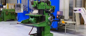
Metal-cutting machines used for mass and large-scale production are called aggregate machines. Their structure is approximately the same; they are produced using standardized work tables, work heads, beds, spindles and other components. If machines are manufactured for single and small-scale production, their design may be unique.
According to the level of automation, the units we are considering are:
- Semi-automatic. They install the workpiece to be processed, start up the equipment, and dismantle the product after processing by a person. The remaining procedures, classified as auxiliary, are performed automatically.
- Automatic. Such machines need to be set up (set the necessary conditions for processing a particular batch of products) and launched. They will perform all work operations themselves.
CNC machines (computer numerical control) deserve special mention. Their work is “guided” by a special program containing a coded complex of numerical values. Such a program sets all the working operations of the machine, starting from the rotation speed of its working tool and ending with the speed of execution of a specific process.
Modern CNC systems contain the following mandatory elements:
- Operator console (console). It makes it possible to enter a program, transfer metal-cutting machines to manual operation mode, set equipment operating modes, and so on.
- Controller. A special device on CNC units that sets and monitors the accuracy of technological control commands, the trajectory of movement of the working device, is responsible for changes and general control of the machine, and also performs additional calculations. These days, a controller can be a powerful industrial computer, a logical programmable device, or a conventional microprocessor.
- Operator panel (screen, display). This CNC element is designed so that the specialist working at the machine can visually observe the process of processing products, and, if necessary, make any changes to the control program.
The essence of operating CNC equipment is relatively simple. First, a control program is compiled for metal-cutting equipment, which is entered into the controller by the operator (a programmer is used for these purposes). When the unit is turned on, the CNC issues sequential commands to the machine components. After completing all commands for processing the part, the equipment turns off.
The high accuracy and speed of performing work operations, which characterize metal-cutting machines equipped with CNC, have led to their active use as part of automatic workshop lines and very large production automated systems.
Brief information about the design of metal-cutting units
The machines of different groups and types that we describe have many common features in their design. Their design is based on the fact that all technical devices and mechanisms installed on the units must guarantee the ability to perform two movements:
- feeding the cutting device or workpiece;
- direct cutting movements.
To ensure the indicated movements, as well as the stable operation of all equipment, a metal cutting machine must have the following structural elements:
- controls (responsible for starting the unit and stopping it, necessary for constant monitoring of the operation of the machine);
- transmission device (it is needed to transmit movement from the engine to the actuator and to convert movement);
- drive (electric, mechanical, pneumatic, hydraulic);
- actuators (devices for cutting metal are placed on them; it is these mechanisms that carry out metal processing).
Grinder grinding machine
rustik427
October 21, 2020
- 0
1 722
Parts drawings + 3d model. Tabletop grinder for processing metal, plastic and wood products. Machine for working with sanding belts.
Machines / KOMPAS-3D
Set the X and Y axes to zero
For my part, since I had plenty of extra stock, I only needed to mark the center of the piece with pencil lines. I then used a pointed tool to grab the pencil cross to set the X and Y axis zero points.
The excess stock gave me enough room for error to keep the finished shape within the confines of the piece of raw wood I used.
Workpiece in the machine
PROJECT OF ORGANIZING CAR SERVICE FOR PASSENGER VEHICLES IN VOLOZHIN
atf_rulezz
October 10, 2020
- 0
1 629
According to the assignment, the maintenance and repair zone for passenger cars was developed in detail. As a result, the area of the zone is 54 m2. In the design part, a VolvoS90 steering simulator was developed. A technological map has been compiled for replacing timing elements of the PSA DW8P engine.
Design of enterprises, sites, workshops / Machine tools
Photorealistic rendering
The result: high-quality photorealistic rendering
Modern CAD software allows you to create high-quality photorealistic renderings of CAD models using technologies such as ray tracing. These renderings give you an idea of what the finished part will look like.
Fishing reel created in Fusion 360
High quality visualization can facilitate communication with the end customer. This will determine whether he and you are happy with everything.
AUTOMATED ELECTRIC DRIVE OF THE MECHANISM FOR MOVEMENT OF THE ROD WITH A STEAMING MILL
Alyona
August 7, 2020
- 0
802
The diploma project briefly outlines the features of the technological process for producing pipes using a pipe rolling unit. The power calculation and selection of the motor for the automated electric drive of the mechanism for moving the rod with the mandrel of the piercing mill, and the calculation of the position controller were carried out. The mathematical model of the power section has been calculated
Automation, electronics / Machine tools
3D outline
This path is ideal for finishing steep walls, so I first used it to finish the outside of the model.
Testing is the key to learning, so make adjustments and test.
If you're unsure, the software usually sets the values fine, so you can leave most of the options as they are.
Contour tool paths on the model
Repair of silicate press SM-816
Alyona
July 16, 2020
- 0
734
In the course project, the labor intensity of repairs was calculated, and a repair and lubrication flow chart was made. The operating principle, purpose and design of the SM-816 press are described, a description of equipment lubrication is made, possible failures are indicated, and the planning and organization of repairs is described.
Project drawings / Machines
