When arranging a site or preparing for the dacha season, the need arises for arches made of profile pipes. They are needed when constructing a greenhouse, assembling a gazebo or canopy. It is expensive to buy already bent arches - the price is twice as high as for the same flat rolled products. The solution is to do it yourself, and to make the process easier (it’s very difficult to do by hand) you need to make a pipe bender for the profile pipe. You will need channels or corners, rolling rollers and some other details. Tools include a grinder with a metal disc, a welding machine, and a ruler.
Profile bender design
The machine for bending profile pipes is structurally different from the usual one. This is due, firstly, to the greater resistance of the profile to bending loads, and secondly, to the fact that the bending radius usually required is large. Therefore, the design contains three rollers. Two of them are installed permanently, one remains movable. Using a movable roller, the radius of curvature changes. In general, there are two types of pipe benders for profile pipes: with a middle movable roller and with an outer one (right or left, as desired).
You can make a pipe bender for a profile pipe in different sizes with your own hands
Pipe bender with middle movable roller
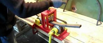
The two outermost rollers are fixedly mounted on the body. They are raised above the plane of the base. For the middle roller, a special U-shaped frame is welded. A long, large-diameter clamping screw is installed in the middle of its jumper. A third bead is attached to the lower end of this screw (can be welded). By rotating this screw, the roller lowers and rises, changing the bending radius of the profile pipe.
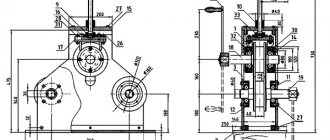
Design of a pipe bender for a profile pipe with a movable middle roller
A cloud is welded to one of the stationary rollers, with the help of which the pipe is rolled through the machine. To make it possible to apply less effort for rolling, two stationary rollers are connected using a chain. To effectively transmit torque, sprockets are welded to the rollers (possibly from a bicycle), and a chain is selected for them. This simple mechanism makes bending a profile pipe much easier.
With extreme movable roller
In this design, the right or left roller is made movable. It moves along with part of the base. This part is connected to the rest of the frame using powerful metal hinges.
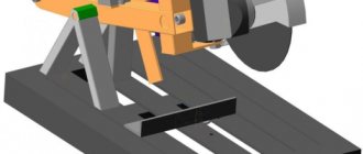
Drawing of a bending machine for profile pipes with a lifting platform
You can change the height using a jack, as shown in the drawing. The height of the platform in this case is selected depending on the height of the jack. The bending radius is changed by lifting the movable part of the table.
Pipe bender for profile pipe with lifting platform
Unlike the previous design, this pipe bender for a profile pipe is driven from the central roller - a handle is welded to it. To reduce the required force, you can also weld the sprocket to two fixed rollers and transmit torque using a chain.
Electric drive type
The electric drive of a profile bender is usually used in amateur workshops with a small area and a small number of operations, as well as in everyday life. Disadvantages include lower pressure and lack of protection against possible overloads.
Energy is supplied by an electric motor, which creates torque and transmits it to the workpiece. The advantages of electric profile benders include:
- Compact and high efficiency.
- High precision during work.
- Operation in semi- or automatic modes is possible.
What materials and design details are needed?
The base of the pipe bender is made from a channel or two welded angles. The thickness of the shelves is at least 3 mm; select the width of the shelves and the back of the channel to match the existing parts. One rule - the base must be massive and reliable.
Several holes can be made along the edges of the platform. Through them you can fix the machine to some heavy base using large diameter self-tapping screws. Fixation is necessary, since when bending pipes with a thick wall, significant forces have to be applied and it is more convenient to work if the machine is firmly fixed.
This is what the frame looks like with welded racks for attaching the movable roller
A few words about rollers. They must be made of good, high-quality, preferably hardened steel. It is on the rollers and on the axles that hold them that most of the load falls.
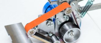
It should also be said about the shape of the rollers. They should not be smooth - there should be rollers along the edges that will prevent the pipe from “walking” during rolling. Only under such conditions will the arc from the profile pipe be smooth and not twisted. Ideally, each pipe size needs its own rollers. But then the design becomes more complicated - they need to be made removable, and a reliable method of fastening must be thought out. The second option is to make videos of complex shapes, such as in the photo. Carve several steps for different pipe sizes.
Rollers for bending profile pipes of different widths
In the same photo you can see that the upper part of the bed is not smooth, but toothed. With the help of such teeth, the rollers can be rearranged to different distances and thus also adjust the bending radius.
In general, homemade bending machines for profile pipes are assembled from what is at hand or what they can find/buy inexpensively. Those who have the opportunity grind out the rollers and insert bearings. Those who don’t have such an opportunity use what they have, right down to the bushings from bicycle wheels. In general, you need to understand the design and
Assembling a pipe bender (step by step)
- The first step, of course, is to prepare a reliable, stable base; this can be a steel sheet 1 cm thick or a concrete base with built-in nuts for fastening other structural elements.
- Next, the installation of the side drive rollers of the installation is carried out.
- After this, you can begin installing the moving parts of the frame.
- Then you should check the moving parts; this work should be taken with special responsibility. You must ensure that the structural elements do not get stuck while performing the work. If the structure is not diagnosed, it may break when tested with a leading hydraulic drive.
- Then the main drive shaft stand is welded.
- Now the stage of work is to secure the central post of the drive shaft; the shaft should be secured with bolts and a lock nut.
- Lastly, the drive handle is attached.
Tricks to make pipe bending easier
To make the rollers move better, bearings are used. But, in principle, for a homemade pipe bender, which will be used only occasionally, you can simply make holders from a corner or channel. Make a hole in them that is slightly larger in size than the axis on which the roller will be mounted. Pass the axle with the roller on through the holes of the holders and somehow fix them (at least weld on a couple of points that will be stoppers). During operation, for better performance, lubricate the rubbing areas with a thick lubricant such as Litol. This is not suitable for industrial and semi-industrial production, but it’s just right for making arcs for a greenhouse or gazebo with your own hands.
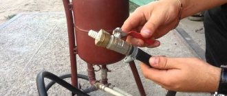
Example of turned beads
There is one more trick that helps reduce the required force when bending a profile pipe. You can use the principle of increasing gears as in a bicycle. By the way, you can use bicycle sprockets. In this case, the handle that drives the rollers is welded to a small star. It is installed somewhere on the body. Larger sprockets are welded onto the shaft axis (but teeth with the same pitch). All this is connected by a suitable chain.
With such a torque transmission device, an electric drive is not needed - it will be easy to work
And one more improvement - if you constantly use a pipe bender for a profile pipe, it makes sense to mechanize it. In this case, they install a motor that operates at low speeds.
Placement method
Stationary. The device is large in size, has high productivity and requires a strong and stable base - a foundation is poured or a metal box is welded. Used in industry to work with large diameters and complex bends.
Portable. They are of medium size. A metal frame or base is created as a base for installation. Suitable for use in workshops and small industries. Self-production is possible.
Manual. A mobile device used for bending thin metal profiles used as a decorative or decorative element. There is no need to create a solid base or frame.
Can be installed on any flat surface without special preparation. Using the drawings allows you to make a manual profile bender with your own hands.
The procedure for bending a profile pipe on homemade machines
It is unlikely that you will be able to obtain the required bending radius in one go - too much force is required for this. It is impossible to create it manually. Receive the required bend in several passes:
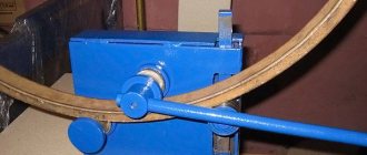
- First, the rollers are aligned so as to obtain a slight bend, the pipe is rolled in one direction, then removed from the rolls, unfolded and inserted on the other side. It is necessary to unfold in order to obtain an evenly curved pipe.
- With the same position of the rollers, it is pulled several times until the curvature is no longer added.
- If the required bending radius is not achieved, change the position of the roller and repeat the steps again.
Rolling pipe bender with electric drive
The change in bending radius is achieved gradually, otherwise you won’t be able to make an arc from a profile pipe on a homemade pipe bender. What to do if you need to repeat the same bend? Make a graduation - note to what height the roller moved, how many times it was rolled in each position. When repeated, the differences, if any, will be insignificant.
The difficulty of bending lies in the fact that there is no scale and it is difficult to obtain the intended bending radius without experience. Sooner or later you will get it, but you can spoil a lot of material in the process.
Pressing
To create a machine based on pressing, you will need to install a matrix and a punch.
Note!
Do-it-yourself compressor: selection of materials and tools for assembly at home + step-by-step instructions for making and assembling yourselfHomemade products for the garage with your own hands: options for products for arranging a garage, detailed diagrams and drawings for creating with your own hands
Do-it-yourself press - design features, choice of manufacturing materials. Step-by-step instructions for making it yourself + simple diagrams and drawings
How to bend a profile pipe without a machine
There are two ways to make an arc from a profile pipe without a profile bender - using welding and a template. Let's start with welding.
Get an arc by welding
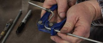
The profile pipe is cut with a grinder on one side. They are made every 15-30 cm, depending on the required radius, cross-section and wall thickness. The cuts should not touch one side - the one that will be on the outside.
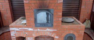
Result of bending by welding
The spare part prepared in this way is bent, giving the desired bend. For reliability, the edges of the arc can be fixed by welding a rod to them. Then welding is carried out along all the cuts, welding them. And the last stage is grinding the weld spots and treating them with anti-corrosion compounds.
Using a template
Thin-walled profiled pipes can be bent by hand using templates. If you need a special shape, it can be cut out of a piece of thick plywood or chipboard and secured to the table using clamps. On the workbench where we will bend the pipes, make about 8-10 holes. The template is placed near these holes.
The process of obtaining an arc from a profile pipe using a template
The holes are repeated at one end of the pipe; with their help, the pipe is attached to the workbench. Now the free end of the pipe begins to be pulled smoothly, forming a bend that follows the shape. You need to pull smoothly, without jerking.
The template can also be made on the ground. Pipes-pegs are driven into the ground (at least half a meter deep). They form the required arc. For emphasis, two additional stakes are driven in, which are located to the side of the arc. The distance you need to step aside is slightly greater than the width of the pipe.
Pattern on the ground
Having inserted the pipe, it is pulled towards the arc. Great efforts are required, the work is hard. This can only be achieved with a thin-walled, seamless pipe. The suture has too much resistance in the seam area. It is very difficult to overcome it manually.
Manual drive type
The cheapest option due to ease of manufacture. The available do-it-yourself profile bending drawings refer specifically to this design option.
The main distinctive features of the manual drive:
- Compact size, simplicity and low cost.
- Common for personal use or small workshops.
- Mainly used for bending profiles of small diameter, which is associated with the creation of low pressure and the inability to use for thicker profiles.
- Low accuracy of the resulting product.
Advice
The Internet contains a large number of not only drawings, instructions and diagrams for creating the required design, but also videos from professionals in their field.
For a more detailed and detailed understanding of how to properly create a profile bending machine with your own hands, we recommend studying these videos. They will help you visualize the scope of work that needs to be done and analyze the main issues that you may encounter when designing a profile bender.
Side Design Guidelines
Profiles with a relatively simple cross-section, for example, square or round (pipes), do not require complication of the side planes. In this case, the exterior is made flat and even, and if complex sections are bent, then the following solutions are chosen:
- The round or oval shape of the rod dictates the formation of a groove or a kind of groove with a cross-section of the appropriate type on the side plane of the roller.
- To bend a profile of rectangular or square cross-section without protruding shelves, the lateral exterior of the disks is made of a regular rectangular shape with sides. In this case, the thickness of the disk is selected taking into account the fact that the outer dimensions of the rolled product fit exactly into the internal space between the sides, which firmly hold the product.
- If you need to bend a corner so that the inner side of the profile is on the outside of the resulting arch (bending along the outer side), then the surface of the working disk is made flat, but a bead is installed for holding. The support disk is made with a flat exterior, and the disks are shifted from one another to a distance of the thickness of the angle shelf.
- In the case of bending the angle along the inside, the working roller is made flat, and the sides are provided on the disks of the stationary shafts.
- When bending a channel, the situation is almost similar to the option with a corner. Bending along the outside requires making a bead on the plane of the working roller, while the stationary disks are made flat. Reverse bending requires retaining flanges on support disks, and the worker is performed with a flat exterior.
- To work with an I-beam, the transverse side section of the working and stationary disks is made in such a size that it corresponds to the internal dimension between the profile flanges. The ends of the disks must fit tightly inside the I-beam profile and prevent its deformation.
- To make an arch from an I-beam, in which there will be shelves at the bottom and top (bending across the shelves), it is necessary to perform a complex configuration on the side planes of the roller, while two sides are made on the support and moving rollers.
It will not be possible to make a roll forming unit that is universal for all types of profiles. An option for a workshop that offers bending services would be to produce separate sets of three discs that are bolted to the shafts and replaced with others if necessary.
Originally posted 2018-03-28 15:20:26.
Main production cycle
To prepare the elements to be bolted together, two pieces are cut from the steel strip. They are designed so that they fit freely into the cavity of the channel. For M12 bolts, holes of the appropriate diameter are drilled in pieces of plates, retreating from the edges at a distance of 10 mm. The finished parts are placed inside the channel and welded.
The prepared longitudinal and transverse parts are connected by welding, resulting in the bed of a roll forming machine. During the assembly process, a shaft is inserted into the structure of the top and two sides. Guide vertical sections of the channel, which were prepared at the initial stage of assembly, are welded to the frame; the clamping mechanism will move along them.
A 22 mm hole is drilled in the upper part of the clamping device for an M20 bolt. The end of the bolt fits freely into the hole, but does not fall out of it; for this, the end is soldered using welding. The guides for moving the carriage are made from two sections of channel, the length of the blanks is equal to the distance between the runners. The holes in the crossbars are made precisely so that they coincide with those previously drilled in the guide parts of the purlins. A hole in the center is drilled in accordance with the diameter of the nut, then it is welded on top.
To fasten the top crossbar, a bolted connection is provided; hardware is inserted into it. Tighten the bolts using engraving nuts. Bearing units are attached to the top of the frame base, and stationary shafts are placed on them. Bearing assemblies are secured with bolts through holes using engraving nuts.
To connect the hub to the gears, it is welded under the chain. The diameter of the hub must correspond to this size at the spindle shaft. A protrusion in the form of a groove is welded on it, and a passage in the form of a groove is machined on the surface of the shaft; when installed, they must coincide. Sometimes, in order to simplify things, the hubs are welded onto the shaft. The gears are then placed on the spindles and secured with two nuts: a locknut and a main nut.
Final works
In the middle part of the guide beam, placed vertically, an axis for the gear and the gate are welded under the collar. The work is performed from the side of the installed gears. The axis is positioned in relation to the guides so that the chain, if necessary, can be removed, and in the working position it is tensioned.
A rod is welded to a steel strip about 50 cm in size, which will serve as a handle. It turns out to be a gate to which a hub is welded from the second end. To make it, they take the rest of the pipe, and it turns out that the diameter of the hub is equal to the internal size of the gears.
The gear is pressed onto the hub handle, it is used to wind the chain; a vice is used for this work. To speed up the pressing process, heat the gear to 120˚, this will cause the mounting hole to expand, and after putting it on it will decrease, and the gear will receive a tight fit.