STATE STANDARD OF THE USSR UNION
MOUTHOW AND DISCHARGE FITTINGS
TYPICAL DIAGRAMS, BASIC PARAMETERS AND TECHNICAL REQUIREMENTS FOR THE DESIGN
GOST 13846-89 (ST SEV 4354-83)
USSR STATE COMMITTEE ON STANDARDS
Moscow
STATE STANDARD OF THE USSR UNION
| MOUTHOW AND DISCHARGE FITTINGS Typical diagrams, main parameters and technical requirements for the design Gush and injection well equipment. Standard schemes, basic parameters and technical requirements for construction | GOST 13846-89 (ST SEV 4354-83) |
Valid from 01/01/90
until 01/01/95
This standard applies to wellhead Christmas tree and injection valves, consisting of a wellhead tree and piping, regardless of the area of application in climatic region and operating environment.
This standard does not apply to wellhead equipment with parallel suspension of well pipelines; for production or injection of coolant, as well as installed on wells with an underwater mouth location.
TYPICAL DIAGRAMS AND MAIN PARAMETERS
1.1. Typical diagrams of fountain trees must correspond to those shown in Fig. 1, injection trees - to hell. 2.
1.2. Typical piping diagrams for Christmas tree and injection valves must correspond to those shown in Fig. 3.
1.3. Typical diagrams of wellhead fittings should be compiled by a combination of standard diagrams of wellhead trees with piping.
Typical diagrams of fountain trees
1
- adapter to the pipe head;
2
- tee;
3
- locking device;
4
— pressure gauge with shut-off and discharge device;
5
- throttle;
6
— counter flange;
7
— cross
Crap. 1
Typical diagrams of injection trees
1 —
adapter to the pipe head;
2
- tee;
3 -
locking device;
4 —
pressure gauge with shut-off and discharge device;
5 -
check valve;
6
— counter flange;
7
— cross
Crap. 2
Typical Xmas tree piping diagrams
injection valves
1 —
counter flange;
2
- locking device;
3 -
pipe head;
4 —
pressure gauge with shut-off and discharge device;
5
- quick connection
Crap. 3
Examples of typical diagrams of fountain fixtures are shown in Fig. 4, injection valves - to hell. 5.
1
- fountain tree (Fig. 1);
2 -
piping (Fig. 3)
Crap. 4
1
— injection tree (Fig. 2);
2 -
piping (Fig. 3)
Crap. 5
1.4. The main parameters of the Christmas tree fixtures must correspond to those indicated in the table. 1.
Table 1
| Conditional bore, mm | Working pressure, MPa | ||
| tree trunk | side branches of the tree | side outlets of the pipe head | |
| 50 | 50 | 50 | 14, 21, 35, 70, 105 |
| 65 | 50, 65 | 50, 65 | |
| 80 | 50, 65, 80 | 14, 21, 35, 70, 105, 140 | |
| 100 | 65, 80, 100 | ||
| 150 | 100 | 21 | |
1.5. The main parameters of injection valves must correspond to those indicated in the table. 2.
table 2
| Conditional bore, mm | Working pressure, MPa | ||
| tree trunk | side branches of the tree | side outlets with head tube | |
| 50 | 50 | 50 | 14, 21, 35 |
| 65 | 50, 65 | 50, 65 | |
| 80 | 65, 80 | 21, 35 | |
1.6. Symbols of wellhead trees and fittings must consist of a name, a code constructed according to the scheme in Appendix 1, and a designation of a regulatory and technical document for supply.
Examples of symbols
Christmas tree with suspension of the well pipeline in the pipe head, with a Christmas tree according to standard scheme 6, with automatic control, with a nominal bore of 80 mm and side branches of 65 mm, for a working pressure of 70 MPa:
Christmas tree fittings AF6A-80/65´70 GOST 13846-89
Trees with a well pipeline suspended in a sub to a pipe head (reel-pipe holder), made according to standard scheme 2, with manual control, with a nominal bore of 65 mm, side branches of 50 mm, for a working pressure of 35 MPa, corrosion-resistant design K2:
Christmas tree EFK2-65/50´35K2 GOST 13846-89
Injection fittings with suspension of the well pipeline in a sub to the pipe head, made according to standard scheme 1, with manual control, with a nominal diameter of the trunk and side branches of 65 mm, for a working pressure of 21 MPa:
Injection fittings ANK1-65´21 GOST 13846-89
The same, with two pipe heads according to the devil. 4b:
Injection fittings ANK1a-65´21 GOST 13846-89
Injection tree with the same parameters and purpose:
Injection tree ENK1-65´21 GOST 13846-89
Marking
The equipment marking code contains the following information: name, code, product designation according to the delivery documentation.
Equipment marking features:
- Name. The abbreviations FA (AF) and AH(HA) denote Christmas tree and injection valves, and the indices EH and EF denote wellhead equipment.
- Installation method. If the pipeline is suspended in a sub, then the index K is indicated. Other installation methods do not have a designation.
- Type of locking mechanism. The presence of a remote control unit is marked with the index D, fully automatic systems are designated - A, combined - B.
- Dimensions. The following marking elements are the internal diameter of the side branches and the EF or EH barrel.
- Operating pressure. This parameter is indicated in numbers in MPa.
If necessary, an index is added to the marking code. denoting a modification or upgrade of a device.
Additionally, the corrosion-resistant design of wellhead equipment is indicated:
- K1 - the content of carbon dioxide in the transported medium does not exceed 6%;
- K2 - the transported medium contains, in addition to carbon dioxide, no more than 6% hydrogen sulfide;
- K3 - the level of CO2 and H2S in the working environment can reach up to 25%.
An example of marking and its decoding:
- AF5V-55/Z5x35 GOST 1Z846-89. This is how fountain fittings are marked, mounted according to standard diagram number five, with a combined type control, D trunk and side outlets of 55.0 and 35.0 mm, respectively. The equipment is designed for operation at an internal pressure of 35 MPa (356.9 kgf/cm2).
TECHNICAL REQUIREMENTS FOR DESIGN
2.1. The nominal diameters of the connecting flanges of wellhead fittings are given in Appendix 2.
2.2. The design of the wellhead fittings must ensure complete tightness with respect to the environment.
2.3. The design of the body parts of the wellhead fittings must ensure the possibility of their pressure testing with the test pressure given in table. 3.
Table 3
| Working pressure Р р, MPa | 14 | 21 | 35 | 70 | 105 | 140 |
| Test pressure R pr, MPa | 2 R R | 1,5 P R | ||||
2.4. The alignment of the holes of the components of the wellhead fittings forming the wellbore passage must ensure the unhindered passage of equipment, instruments and devices lowered into the well.
2.5. The design of the piping must provide the ability to suspend well pipelines in the tubing head body, control pressure and control the flow of well fluid in the annular (annulus) space.
It is allowed to suspend the well pipeline in a sub to the pipe head.
2.6. The choke in the fountain fittings must be adjustable.
It is allowed to use unregulated chokes at the request of the consumer.
2.7. It is allowed to constructively combine, without changing the standard diagram, wellhead fittings, several components into one block.
2.8. It is allowed to retrofit fountain fittings with shut-off devices and a check valve, and Christmas trees with a choke.
2.9. At the customer's request, the wellhead valve design must provide the ability to:
installation of a Christmas tree with excess pressure in the well pipeline;
injection of corrosion and hydrate formation inhibitors into the well pipeline and annulus in flowing wells;
measuring the pressure and temperature of the well environment in the side branches of the fountain tree.
2.10. At the consumer's request, the fountain fittings should include:
automatic safety devices;
remote controlled locking devices;
devices that provide the ability to connect downhole equipment with a surface control system;
quick-assembly connection for periodically installed wellhead equipment (devices).
A diagram of the Christmas tree with a control system is given in Appendix 3.
2.10.1. Pneumatic pilots (automatic safety devices) must ensure shut-off of the well environment in the event of a regulated deviation from the specified well operation mode.
2.10.2. The design of locking devices with remote control must provide for the possibility of manual control.
Material requirements
For the manufacture of equipment, carbon, low-alloy, and martensitic stainless steel grades of classes AA, BB, SS, DD, EE, FF, NN are used. Elements and structural units operating in a hydrogen sulfide environment and when exposed to carbon dioxide must comply with the parameters specified in table. 4 and 5.
Table 4. Chemical composition of materials.
| Element | Substance content in % | ||
| Low alloy and carbon grade steels | Corrosion-resistant steel grades | 45K steel for flanged elements with weld necks | |
| WITH | 0,45 | 0,15 | 0,35 |
| Mn | 1,80 | 1,00 | 1,05 |
| Si | 1,00 | 1,50 | 1,35 |
| R | 0,035 | 0,035 | 0,05 |
| S | 0,025 | 0,025 | 0,05 |
| Ni | 1,00 | 4,50 | — |
| Cr | 2,75 | 11,0-14,0 | — |
| Mo | 1,50 | 1,00 | — |
| V | 0,30 | — | — |
Table 5. Mechanical properties.
| Material | Yield strength s 0.2, MPa (Psi) | Temporary resistance, MPa (Psi) | Relates. extended d 5, % | Transverse narrowing y, % | Hardness, HB |
| not less | |||||
| K248 (36K) | 248 (Z6 000) | 48Z (70,000) | 21 | — | 140 |
| K310 (45K) | Z10 (45,000) | 19 | Z2 | ||
| K414 (60K) | 414 (60 000) | 586 (85 000) | 18 | Z5 | 174 |
| K517 (75K) | 517 (75 000) | 655 (95 000) | 17 | 197 | |
To increase the strength and hardness of equipment elements, blanks for its manufacture are subjected to additional heat treatment and hardening. Rolled metal undergoes a series of tests, including assessment of impact strength and resistance to compressive, tensile and bending loads.
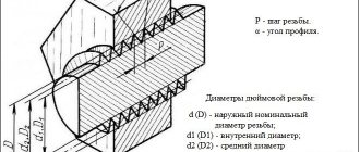
CONDITIONAL SIZES OF CONNECTING FLANGES FOR MOUTHOUT AND DISCHARGE FITTINGS
| Conditional bore, mm | Working pressure, MPa | Conditional bore, mm | |
| top flange of the pipe head | pipe head bottom flange | ||
| 50, 65, 80 | 14 | 180 | 180*, 280 |
| 21, 35 | 280 | ||
| 50, 65 | 70, 105 | ||
| 80 | 70, 105, 140 | ||
| 100 | 14, 21, 35, 70, 105, 140 | 230 | |
| 150 | 21 | 280 | 350 |
* Less preferred conditional passage.
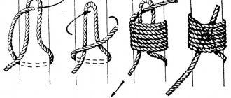
Christmas tree fittings, their diagrams and purpose
Christmas tree equipment is designed to seal the wellhead, control and regulate the operating mode of wells (production and injection).
The fountain fittings consist of a pipe head and a fountain tree (Fig. 2.1).
The tubing head is mounted directly on the casing head and is intended for suspending one or more tubing strings and sealing at the mouth of the annular spaces. The pipe head must ensure the passage of liquid or gas into the interpipe spaces, and also allow you to control the pressure in them and perform the necessary well studies. Columns of lifting pipes are suspended from the pipe head on a thread or coupling. In the first case, with a single-row elevator design, the pipes are suspended on a stem reel; with a double row, the inner row of pipes is on the stem spool, and the outer row is on the tee of the pipe head.
The flow tree is mounted on the pipe head and is designed to direct liquid and gas taken from the well into the manifold, regulate and monitor the operation of the flowing well.
The main parts and assemblies of the Christmas tree fittings (Fig. 2.1) are a cross 1, which has two side outlets, a tee 2, which has one side outlet, a coil or sub 3, a shut-off device 4, a flange for a pressure gauge or buffer 5, a tap 6, a pressure gauge 7, throttle 8, plug 9, flange 10.
The cross and tee make it possible to divert the produced mixture to the manifolds or communicate with one of the interpipe spaces. The tubing string can be suspended on these same parts. The column is suspended directly on this thread or through a transfer pipe. A spool or sub is used for hanging tubing or for transitioning from one size of fittings to another.
Rice. 2.1. Diagram of flanged Christmas tree fittings
1
— crosspiece;
2
- tee;
3
— pipe head sub (coil);
4 —
stem valve;
5
- buffer; b - valve or edge; 7 - pressure gauge;
8
— throttle;
9 - plug; 10 -
flange
The vertical, trunk part of the tree is made of a tee - one or two strings, or a cross - two strings. Based on this criterion, the fittings are divided into tee and cross fittings. Christmas tree fittings diagrams for this feature are regulated by GOST 13846-84, according to which six typical fittings diagrams are established (Fig. 2.2): schemes 1-4 - tee, schemes 5, 6 - cross.
Rice. 2.2. Typical diagrams of Christmas tree fittings
1 - pressure gauge; 2 —
locking device to the pressure gauge;
3 —
flange for pressure gauge;
4
- locking device;
5 —
tee, cross;
6
- throttle;
7 — pipe head sub; 8
— counter flange;
9 -
pipe head
Tee fittings are recommended for use at low and medium pressures. Tee fittings with a two-string tree are recommended for wells whose products contain mechanical impurities.
Cross and tee single-string fittings are designed for wells whose products do not contain mechanical impurities.
For medium and high pressures it is recommended to use cross fittings. The cross fittings are significantly lower than the tee fittings, which makes it easier to maintain. The disadvantages of cross fittings include the fact that if one of the branches fails, it is necessary to close the lower shaft shut-off device, and therefore stop the well. For tee fittings with an upper working outlet, if it fails, you can close the middle stem valve and put the lower outlet into operation.
When exploring wells, it is often necessary to install a lubricator above the fountain tree to lower a particular device. For this purpose, an upper stem locking device is provided in the tee and cross fittings.
The code of the Xmas tree, depending on its layout, design, method of controlling the valves, nominal diameter, pressure of climatic design and corrosion resistance, can include nine or more alphabetic and digital designations.
Locking devices are used to completely close or completely open the flow section of a barrel or outlet. Adjusting flow parameters by incompletely closing the shut-off device is not allowed. To adjust the flow parameters and, consequently, the operating mode of the well, special units are used - chokes (chokes). Fittings
They are mainly used of the unregulated type (Fig. 2.4).
In some cases, with a low abrasive content, adjustable fittings are installed (Fig. 2.5). In this fitting, the gas stream changes its direction by 90°. The flow area of the fitting is created between the needle - tip 3 and the fitting bushing 2.
Shut-off devices for Christmas tree fittings
Shut-off devices for Christmas tree fittings are manufactured in three types:
1) plug valves with lubricant according to TU 26-14-24-77;
2) direct-flow valves with lubricant type ZM and ZMS with a single-plate gate according to TU 26-16-45-77;
3) direct-flow valves with ZMAD lubricant with a two-plate gate according to TU 26-02-728-76 “Equipment of oil and gas wellheads for an operating pressure of 70 MPa.”
Depending on the operating conditions, depending on the composition of the well environment, shut-off devices are manufactured in three versions:
1) for oil, gas and gas condensate with a content of H2S and CO2 up to 0.003% by volume each;
2) H2S and CO2 up to 6% by volume each;
3) CO2 up to 6% by volume.
Gate valves and taps are used in the stem and outlet parts of Christmas tree fittings. Valves are installed in front of the pressure gauges.
Lubricated plug valves compare favorably with gate valves (Fig. 2.6). To open or close it, just turn plug 2 by 90°. The sealing surfaces of the valve are coated with lubricant and are not washed off by the flow of the medium.
The straight-through valve (Fig. 2.9) operates on the principle of self-sealing. The valve spindle 1 has a rolling support and therefore M2 is approximately 0.
To reduce the axial forces acting on the valve spindle, a relief rod is used. Both types of valves have a common drawback - to open and close it is necessary to make several turns of the flywheel, applying force.
Valves are used on auxiliary lines.
EXAMPLE OF A TYPICAL DIAGRAM OF A CHOWT FIXTURE WITH A CONTROL SYSTEM
1
— control station;
2
— sub to the pipe head;
3
— counter flange;
4 -
pipe head;
5
- manually operated locking device;
6 —
pressure gauge with shut-off and discharge device;
7
— locking device with remote control;
8 —
cross;
9
- adjustable throttle;
10 —
air pilot (automatic safety device)
Note. The diagram does not show sensors for pressure, temperature, gas contamination, etc.
Requirements for welded joints
In the manufacture of valves, fittings and other elements of downhole equipment, welding is used, as well as corrosion-resistant or hardening surfacing. Certification of the work performed is carried out by the manufacturer. Based on the test results, after determining the properties and qualities of the welded joints, a protocol is drawn up.
Welding work is performed using GOST 9467 electrodes and GOST 2246 welding wire. The characteristics of connecting seams must comply with ASME standards, the requirements of GOST 5264, GOST 14771, GOST 871Z, GOST 160Z7.
Heating of the material and heat treatment of connecting seams is carried out taking into account the characteristics of the materials used and operating conditions. Welding or hardfacing can be carried out by certified welders. Heat treatment of manufactured equipment is carried out by qualified specialists - operators of thermal installations. The quality of welds is determined by certified inspectors.
The quality of surfacing, strength and density of connecting seams is carried out using non-destructive testing methods. Determining the quality of connecting and surfacing welds includes a number of tests:
- Visual and measuring control. Templates, magnifying equipment, and measuring instruments are used for testing.
- Radiography (RG). X-rays are used to detect internal defects. This method allows you to detect defects whose size is less than 1% of the thickness of the base or deposited metal.
- Luminescent or color flaw detection. The metal surface is coated with a special paint or treated with a fluorescent compound and irradiated with an ultraviolet lamp. This method makes it possible to identify surface defects, lack of fusion, unfilled craters, metal microcracks, and undercuts.
- Ultrasonic flaw detection. The principle of this technique is based on the ability of ultrasonic waves to reflect from a surface, which may have different acoustic properties. Ultrasound testing allows you to accurately determine the location and size of defects.
- Steelscoping of metal. This is a method that allows you to determine in the shortest possible time the chemical composition of the connecting seam, strengthening or anti-corrosion surfacing, and also measure the thickness of the layer.
Tests are performed after thermal and mechanical treatment, if it is provided for in the regulatory and technical documentation.