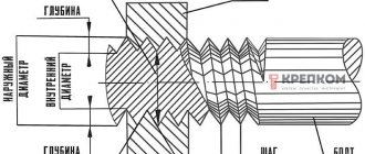
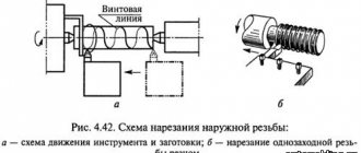
The term “thread” is used to define helical grooves having a constant cross-section and pitch, applied to the side surfaces of a cylindrical or conical shape. It is used for organizing threaded connections and screw (gear-screw) gears. Used in machines, engineering structures, etc.
It is characterized by such indicators as the unit of measurement of diameter, location, profile of the generatrix of the surface on which it is applied, purpose, direction, number of passes. It is these parameters that are decisive when choosing one type of thread or another.
Pipe thread
Pipe threads are a group of standards intended for connecting and sealing various types of structural elements using pipe threads. The quality of work when cutting grooves has a great influence on the reliability of the connection and the structure obtained in this way. Particular attention should be paid to the correlation of the thread with the axis of the pipe to which it is applied.
When cutting threads manually using a die, the alignment is far from ideal, which can affect the reliability and quality of the connection. As for the use of tools such as a lathe or electric threading machine, the use of threading heads with an accurate threading knife , here the indicators of the applied thread are comparable to theoretical values.
Our catalog contains thread-cutting machines, thread-cutting dies, heads, knives that ensure the performance of work with high precision. All equipment fully complies with international standards in this area.
4. NOTATION
4.1. The thread symbol must include: letters ( R
- for tapered external thread,
Rc
- for tapered internal thread,
Rp
- for cylindrical internal thread) and thread size designation.
The symbol for left-hand threads is supplemented with the letters L H.
Examples of thread designations:
external pipe tapered thread 11/2: R
11/2
internal pipe tapered thread 11/2: Rc
11/2
internal pipe cylindrical thread 11/2: RP
11/2
left hand thread:
R
11/2
L.H.
;
Rc
11/2
L.H.
;
R.P.
11/2
LH.
4.2. A threaded connection is designated by a fraction, for example, or Rc
/
R
, the numerator of which indicates the letter designation of the internal thread, and the denominator - the external thread, and the thread size.
Examples of threaded connection designations:
pipe conical thread (internal and external);
; ;
internal pipe cylindrical thread (with tolerances according to this standard) and external pipe tapered thread:
; ;
internal pipe cylindrical thread of accuracy class A according to GOST 6357-81 and external pipe conical thread:
; .
Tapered pipe thread, R (BSPT)
Used for organizing pipe conical connections, as well as for connecting internal cylindrical and external conical threads (GOST 6357-81). Based on BSW, it is compatible with BSP.
The sealing function in connections using BSPT is performed by the thread itself (due to its compression at the connection point when the fitting is screwed in). Therefore, the use of BSPT must always be accompanied by the use of a sealant.
This type of thread is characterized by the following parameters:
- GOST 6211-81
—Basic standards of interchangeability. Conical pipe thread. - ISO R7
- DIN 2999
- BS 21
- JIS B 0203
designation based on the profile shape – inch thread with a taper (profile in the form of an isosceles triangle with an apex angle of 55 degrees, cone angle φ=3°34′48″).
When designating, a letter index of the thread type is used (R for external and Rc for internal) and a digital indicator of the nominal diameter (for example, R11/4 - conical pipe thread with a nominal diameter of 11/4). The index LH is used to designate left-hand threads.
Thread parameters
Inch thread with taper 1:16 (cone angle φ=3°34′48″). The profile angle at the apex is 55°.
Symbol: letter R for external threads and Rc for internal threads (GOST 6211-81 - Basic norms of interchangeability. Conical pipe threads), numerical value of the nominal thread diameter in inches (inch), letters LH for left-hand threads. For example, a thread with a nominal diameter of 1.1/4 is designated as R 1.1/4.
Table 3
Designation of thread size, steps and nominal values of the outer, middle and inner diameters of conical pipe threads (R), mm
| Thread size designation | Step P | Thread length | Thread diameter in the main plane | |||
| Working | From the end of the pipe to the main plane | Outer d=D | Average d2=D2 | Internal d1=D1 | ||
| 1/16″ | 0,907 | 6,5 | 4,0 | 7,723 | 7,142 | 6,561 |
| 1/8″ | 6,5 | 4,0 | 9,728 | 9,147 | 8,566 | |
| 1/4″ | 1,337 | 9,7 | 6,0 | 13,157 | 12,301 | 11,445 |
| 3/8″ | 10,1 | 6,4 | 16,662 | 15,806 | 14,950 | |
| 1/2″ | 1,814 | 13,2 | 8,2 | 20,955 | 19,793 | 18,631 |
| 3/4″ | 14,5 | 19,5 | 26,441 | 25,279 | 24,117 | |
| 1″ | 2,309 | 16,8 | 10,4 | 33,249 | 31,770 | 30,291 |
| 1.1/4″ | 19,1 | 12,7 | 41,910 | 40,431 | 38,952 | |
| 1.1/2″ | 19,1 | 12,7 | 47,803 | 46,324 | 44,845 | |
| 2″ | 23,4 | 15,9 | 59,614 | 58,135 | 56,565 | |
| 2.1/2″ | 26,7 | 17,5 | 75,184 | 73,705 | 72,226 | |
| 3″ | 29,8 | 20,6 | 87,884 | 86,405 | 84,926 | |
| 3.1/2″ | 31,4 | 22,2 | 100,330 | 98,851 | 97,372 | |
| 4″ | 35,8 | 25,4 | 113,030 | 111,551 | 110,072 | |
| 5″ | 40,1 | 28,6 | 138,430 | 136,951 | 135,472 | |
| 6″ | 40,1 | 28,6 | 163,830 | 162,351 | 160,872 | |
Pipe cylindrical thread. GOST 6357 - 81
Parameter Unit: Inch
Direction: Left
Accuracy class: Class A (increased), Class B (normal)
Why in inches?
The inch size came to us from our Western colleagues, since the requirements of the GOST are formulated on the basis of BSW (British Standard Whitworth or Whitworth thread). Joseph Whitworth (1803 - 1887), a design engineer and inventor, demonstrated the screw profile of the same name for detachable connections back in 1841 and positioned it as a universal, reliable and convenient standard.
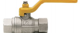
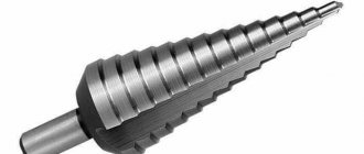
This type of thread is used both in the pipes themselves and in the elements of pipe connections: locknuts, couplings, elbows, tees ( see picture above
). In the profile section we see an isosceles triangle with an angle of 55 degrees and roundings at the tops and bottoms of the contour, which are made for high tightness of the connection.
Threading of threaded connections is carried out on sizes up to 6”. All larger pipes are fixed by welding to ensure a reliable connection and prevent rupture.
Symbol in the international standard
International: G
Japan: PF
UK: BSPP
The letter G and the bore diameter (internal Ø) of the pipe are indicated in inches. The outer diameter of the thread itself is not included in the designation.
Example:
G 1/2 - external cylindrical pipe thread, internal pipe Ø 1/2". The outer diameter of the pipe will be 20.995 mm, the number of steps over a length of 25.4 mm will be 14.
The accuracy class (A, B) and the direction of turns (LH) can also be indicated.
For example:
G 1 ½ - B - cylindrical pipe thread, internal Ø 1 ½ inches, accuracy class B.
G1 ½ LH- B - cylindrical pipe thread, internal Ø 1 ½ inches, accuracy class B, left.
The make-up length is indicated by the latter in mm: G 1 ½ -B-40 .
For internal pipe cylindrical threads, only the Ø of the pipe for which the hole is intended will be indicated.
size table
| Thread size | Thread pitch, mm | Threads per inch | Thread diameters | |||
| Row 1 | Row 2 | d=D | d2=D2 | d1=D1 | ||
| 1/16″ | 0,907 | 28 | 7,723 | 7,142 | 6,561 | |
| 1/8″ | 9,728 | 9,147 | 8,566 | |||
| 1/4″ | 1,337 | 19 | 13,157 | 12,301 | 11,445 | |
| 3/8″ | 16,662 | 15,806 | 14,950 | |||
| 1/2″ | 1,814 | 14 | 20,955 | 19,793 | 18,631 | |
| 5/8″ | 22,911 | 20,749 | 20,587 | |||
| 3/4″ | 26,441 | 25,279 | 24,117 | |||
| 7/8″ | 30,201 | 29.0З9 | 27,877 | |||
| 1″ | 2,309 | 11 | 33,249 | 31,770 | 30,291 | |
| 1⅛» | 37,891 | 36,418 | 34,939 | |||
| 1¼» | 41,910 | 40,431 | 38,952 | |||
| 1⅜» | 44,323 | 42,844 | 41,365 | |||
| 1½» | 47,803 | 46,324 | 44,845 | |||
| 1¾» | 53,746 | 52,267 | 50,788 | |||
| 2″ | 59,614 | 58,135 | 56,656 | |||
| 2¼» | 65,710 | 64,231 | 62,762 | |||
| 2½» | 75,184 | 73,705 | 72,226 | |||
| 2¾» | 81,534 | 80,055 | 78,576 | |||
| 3″ | 87,884 | 86,405 | 84,926 | |||
| 3¼» | 93,980 | 92,501 | 91,022 | |||
| 3½» | 100,330 | 98,851 | 97,372 | |||
| 3¾» | 106,680 | 105,201 | 103,722 | |||
| 4″ | 113,030 | 111,551 | 110,072 | |||
| 4½» | 125,730 | 124,251 | 122,772 | |||
| 5″ | 138,430 | 136,951 | 135,472 | |||
| 5½» | 151,130 | 148,651 | 148,172 | |||
| 6″ | 163,830 | 162,351 | 160,872 | |||
How to determine the pitch of an inch thread
I’ll give you a picture from the English-language Internet that clearly demonstrates the technique. Pipe threads are characterized not by the size between the tops of the profile, but by the number of turns per 1 inch along the thread axis. A regular tape measure or ruler can help. Apply it, measure one inch (25.4 mm) and visually count the number of steps.
In the picture with an example ( see above
) threads - from English these are literally “threads of thread”. In this case there are 18 of them. by one inch.
It’s even easier if you have a thread gauge for inch threads lying around in your tool box. It is very convenient to take measurements, but it must be remembered that inch threads may differ in the apex angle of 55° and 60°.
| Thread pitch P, mm | Threads per inch |
| 0.907 | 28 |
| 1,337 | 19 |
| 1,814 | 14 |
| 2,309 | 11 |
NPSM (National pipe thread) thread
Complies with American standard NSI/ASME B1.20.1.
This type of thread is characterized by the following parameters:
- designation according to the profile shape - inch cylindrical pipe thread (profile in the form of an isosceles triangle with an apex angle of 60 degrees);
- theoretical profile height (H) - 0.866025Р;
- Thread size range: 1/16" to 24" (in accordance with NSI/ASME B36.10M, BS 1600, BS EN 10255 and ISO 65).
Table 4
Designation of thread size NP, steps and nominal values of outer, middle and inner thread diameters, mm
| Thread size designation | Threads per inch | Thread length | Thread diameter in the main plane | |||
| Working | From the end of the pipe to the main plane | Outer d=D | Average d2=D2 | Internal d1=D1 | ||
| 1/16″ | 27 | 6,5 | 4,064 | 7,895 | 7,142 | 6,389 |
| 1/8″ | 7,0 | 4,572 | 10,272 | 9,519 | 8,766 | |
| 1/8″ | 18 | 9,5 | 5,080 | 13,572 | 12,443 | 11,314 |
| 3/8″ | 10,5 | 6,096 | 17,055 | 15,926 | 14,797 | |
| 1/2″ | 14 | 13,5 | 8,128 | 21,223 | 19,772 | 18,321 |
| 3/4″ | 14,0 | 8,611 | 26,568 | 25,117 | 23,666 | |
| 1″ | 11½ | 17,5 | 10,160 | 33,228 | 31,461 | 29,694 |
| 1.1/4″ | 18,0 | 10,668 | 41,985 | 40,218 | 38,451 | |
| 1.1/2″ | 18,5 | 10,668 | 48,054 | 46,287 | 44,520 | |
| 2″ | 19,0 | 11,074 | 60,092 | 58,325 | 56,558 | |
| 2.1/2″ | 8 | 72,699 | ||||
| 3″ | 88,608 | |||||
| 3.1/2″ | 101,316 | |||||
| 4″ | 113,973 | |||||
| 5″ | 141,300 | |||||
| 6″ | 168,275 | |||||
| 8″ | 219,075 | |||||
| 10″ | 273,050 | |||||
| 12″ | 323,850 | |||||
TOLERANCES
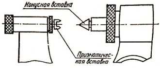
3.1. Axial displacement of the main plane D1 l
2 external and D2
l
2 internal threads (Fig. 4) relative to the nominal location should not exceed the values specified in table. 3.
The displacement of the main plane is total, including deviations of the average diameter, pitch, angle of inclination of the side of the profile and cone angle.
3.2. The maximum deviations of the average diameter of the internal cylindrical thread must correspond to those indicated in the table. 3.
Crap. 4
Note. In the main plane, the average diameter has a nominal value.
Table 3
Dimensions in mm
| Thread size designation | Offset of the main thread plane | Maximum diameter deviations D 2 internal cylindrical threads | |
| ±D1l 2 | ±D2l 2 | ||
| 1/16 | 0,9 | 1,1 | ±0,071 |
| 1/8 | |||
| 1/4 | 1,3 | 1,7 | ±0,104 |
| 3/8 | |||
| 1/2 | 1,8 | 2,3 | ±0,142 |
| 3/4 | |||
| 1 | 2,3 | 2,9 | ±0,180 |
| 11/4 | |||
| 11/2 | |||
| 2 | |||
| 21/2 | 3,5 | 3,5 | ±0,217 |
| 3 | |||
| 31/2 | |||
| 4 | |||
| 5 | |||
| 6 | |||
Note. Limit deviations ±D1 l
2 and ±D2
l
2 do not apply to threads with lengths shorter than those indicated in table. .
3.3. It is allowed to connect an external conical thread with an internal cylindrical thread of accuracy class A according to GOST 6357-81.
3.4. Recommended maximum deviations of individual thread parameters are given in the reference appendix.
NPT thread (National pipe thread)
NPT is an American standard used for inch pipe threads. It is used, as a rule, in connections for which it is important to ensure increased tightness of pipes under conditions of exposure to high pressures (gas or liquid). The NPT thread meets the requirements established by the domestic standard GOST 6111-52 (classified as an inch conical pipe thread with a profile angle of 60 degrees).
This type of thread is characterized by the following parameters:
- designation according to profile shape:
- inch pipe cone (angle φ=3°34′48″, taper 1:16) - American standard;
- pipe inch tapered thread with a profile angle of 60 degrees - domestic standard;
- theoretical profile height (H) – 0.866025Р.
Also, in accordance with ANSI/ASME B1.20.1, cylindrical threads (NPS) also belong to this type. Within this standard there is also NPTF. Its peculiarity is the formation of a seal due to the compression of the thread at the connection point.
Inch pipe thread (American standard) (NPT) with a taper of 1:16 (cone angle φ=3°34′48″) or cylindrical (NPS) thread according to ANSI/ASME B1.20.1. The profile angle at the apex is 60°, the theoretical profile height is Н=0.866025Р. NPT thread corresponds to GOST 6111-52 - Conical inch thread with a profile angle of 60 degrees. There is also an NPTF thread - compaction occurs due to thread compression.
Applications and features of inch threads for pipes
Pipe threads are used on pipes and other elements of the pipeline system: fittings, shut-off and control valves, flanges.
Standardized by international specifications. Products with threads are widely used on the following systems:
- where the use of welding is undesirable or impossible;
- where it is necessary to form a dismountable connection;
- which are not subject to pressure or temperature surges, etc.
Previously, each manufacturer applied its own thread, which corresponded to paired parts manufactured in the same production. The need for unification arose when a discrepancy between various parts with threads from different manufacturers was discovered and, as a result, it became impossible to sell or exchange threaded metal products.
The thread differs in such parameters as
- profile angle (55°, 60°);
- shape of protrusions and depressions (sharp, flat, round);
- step (large, small);
- shape (conical, cylindrical);
- number of threads per inch.
In order to satisfy the needs of all industries, there are several types of threads. Moreover, the USA and Europe have their own standard pipe threads, which were created independently of each other. Despite some similarities in parameters, dimensions, and scope of application, threaded pipe fittings of different types cannot be used, since the only result of such a combination is damage to the products and poor quality of connections of pipeline elements.
Symbols and tables for tapered threads
The tapered thread and its designation in the presented table must comply with established state GOSTs, since it is used to create a strong connection of pipes where there is high pressure or external high mechanical loads are imposed. Examples of application include factors such as:
- Obtaining a strong connection of pipes that are laid under a dirt road at an insignificant depth, the whole point is that loads are placed on them by vehicles passing along the road.
- Also, tapered threads are used to connect pipelines in places where welding cannot be used or it is not possible to use it. This may be an explosive environment, which precludes the use of welding equipment.
- In addition, it is used in cases where the cutting has signs of wear or it is not possible to completely replace this element. But it is worth noting that this type of product is not permanent, since replacing a worn-out element is an inevitable measure.
It is mainly used for sealing pipes used in laying water and gas pipelines, providing greater reliability of the connection even in the most extreme conditions.
Thread matching
Correspondence table for various types of threads for general engineering, oil and gas assortments
| Thread type and designation example | Application area | Regulatory normative and technical documents | |
| Domestic: Russia and CIS countries | Foreign | ||
| Metric M12 - large step; M20x2 or MF 2 - fine step; M20x2 LH - left-hand thread | General machine and construction applications | GOST 24705-81 “Metric thread. Main dimensions" | 1.TSO 724; 2. DIN 13 (Germany); 3. BS 3643 (England); 4. ANSI/ASME B1.13M (USA); 5. NF E 03-50 (France); 6. JIS B 0205, JIS B 0207 (Japan) |
| Trapezoidal thread Tg 40×7; Tg 40×7 LH - left-hand thread | Lead screws in general engineering | GOST 24737-81 “Single-start trapezoidal thread. Main dimensions" | 1. ISO 2904; 2. DIN 103 (Germany); 3. BS 5346 (England); 4. NF E 03-618 (France); 5. JIS B 0216 (Japan) |
| Pipe cylindrical thread (55°) G 1 1/2 -A - cylindrical pipe thread of accuracy class A | Used in cylindrical threaded connections. | GOST 6357-81 “Cylindrical pipe thread” | 1. ISO 228/1; 2. DIN ISO 228, DIN 259 (Germany) 3. BS2779 (England); 4. ANSI/ASME Bl,20.1, ANSI B 1.20.3 (USA) 5. NF E 03-005 (France); 6. J1S B 0202 (Japan) |
| Tapered pipe thread (55°) - or British pipe taper thread BSPT Rc 1 1/2 - tapered internal thread; Rp 1 1/2 - cylindrical internal thread; R 1 1/2 - external thread | In gas water supply and sewer fittings. For greater tightness, use conn. internal cylindrical with external conical thread. | GOST 6211-81 “Conical pipe thread” | 1. ISO 7/1 2. DIN 2999, DIN 3858 (Germany) 3. BS 21 (England); 4. ANSI/ASME B 1.20.1, ANSI B 1.20.3 (USA) 5. NF E 03-004 (France); 6. JIS B 0203 (Japan) |
| Unified thread (ISO inch thread ) 1/4-20 UNC - 2 A or 0.250-20 UNC - 2 A - external, coarse pitch; 10-32 UNF - 2 B or 0.190-32 UNF - 2 B - internal, with a large pitch; 2 1/2-16 UN - 3 A or 2.250-16 UNC - 3 A - external, coarse pitch | General engineering and construction applications, common in the USA | Not regulated | 1. ISO 725; 2. BS 1580 (England); 3. ANSI/ACME B 1.1 (USA) |
| Metric thread with MJ MJ 6 xl | In the aviation and space industry | Not regulated | 1.TS0 5855; 2. DIN ISO 5855 (Germany); 3. BS 6293 (England) |
| Unified (inch) external thread with standardized root radius UNR, UNRC, UNRF and UNREF - other designations are as in paragraph 5. | Not regulated | 1. ANSI B 1.1 (USA) | |
| Unified (inch) thread with increased root radius UNJ, UNJC, UNJF and UNJEF - other designations are as in paragraph 5. | Used in the aviation and space industries | Not regulated | 1. ISO 3161; 2. BS 4084 (England); 3. ANSI B 1.1 (USA) |
| Unified (inch) thread with special diameters, pitches and make-up lengths UNS - other designations are as in paragraph 5. | Not regulated | 1. ANSI B 1.1 (USA) | |
| Straight inch Whitworth thread 1/4-20 BSW or BSF, BSP | In gas, water and sewer fittings. | Industry standards, for example, OST NKTP 1260 | 1.DIN 49301, DIN 477, DIN 4668 (Germany); 2. BS 84:1956 (England) |
| Trapezoidal thread 13/4-4 ACME-2G | Lead screws in general engineering | Not regulated | 1. BS 1104 (England); 2. ANSI B 1.5 (USA); 3. JS B 0222 (Japan) |
| Trapezoidal thread with reduced profile height 0.500-20 STUB ACME | Lead screws in general engineering | Not regulated | 1. ANSI B 1.8 (USA) |
| Thrust thread S48x8 | General mechanical engineering | OST 10177-82 “Resistant thread. Profile and main dimensions" | 1. DIN 513 (Germany) |
| Armored Pipe Thread Pg21 | Used in electrical engineering | Not regulated | 1. DIN 40430 |
| Thrust inch (American Buttress) 2.5-8 BUTT | Casing pipes in mining | Not regulated | 1. ANSI B 1.9 (USA) |
| Buttress thread (API Battress) | Casing pipes used in the oil and gas industry. | Not regulated | 1. API special 5V (USA) |
| Inch cylindrical thread with a profile angle of 55° | Industry Standards | ||
| Pipe conical inch thread with a profile angle of 60° KZ/8″ designation according to GOST 3/8-18 NPT - designation according to ANSI/ASME | Fittings and connections for machines and machines | GOST 6111-52 “Inch tapered thread with a profile angle of 60°” | 1. ANSI/ASME B 1.20.1 (USA) |
| 60° Inch Pipe Thread 1/8-27 NPTF | Sealed fuel line threads | Not regulated | 1. ANSI B 1.20.3 (USA) |
| Round thread RD | Food industry and fire extinguishing systems | Not regulated | 1. DIN 405 (Germany) |
| Lock thread according to API 3-117 - designation according to GOST 4 1/2 Reg - designation according to API | Rotating drilling tools (rods, bits, etc.) | GOST 28487-90 “Conical locking thread for drill string elements” | 1. API specification 7 (USA) |
| RD locking thread | Tubing, casing and drill pipes | 1. API specification 5B (USA) | |
Conversion table for inch to metric sizes
1 inch (inch) = 25.4 mm.
| Inches | mm | Inches | mm |
| 1/8 | 3,2 | 2 5/8 | 66,7 |
| 1/4 | 6,4 | 2 3/4 | 69,8 |
| 3/8 | 9,5 | 2 7/8 | 73,0 |
| 1/2 | 12,7 | 3 | 76,2 |
| 5/8 | 15,9 | 3 1/8 | 79,4 |
| 3/4 | 19,0 | 3 1/4 | 82,6 |
| 7/8 | 22,2 | 3 3/8 | 85,7 |
| 1 | 25,4 | 3 1/2 | 88,9 |
| 1 1/8 | 28,6 | 3 5/8 | 92,1 |
| 1 1/4 | 31,8 | 3 3/4 | 95,2 |
| 1 3/8 | 34,9 | 3 7/8 | 98,4 |
| 1 1/2 | 38,1 | 4 | 101,6 |
| 1 5/8 | 41,3 | 4 1/8 | 104,8 |
| 1 3/4 | 44,4 | 4 1/4 | 108,8 |
| 1 7/8 | 47,6 | 4 3/8 | 111,1 |
| 2 | 50,8 | 4 1/2 | 114,3 |
| 2 1/8 | 54,0 | 4 5/8 | 117,5 |
| 2 1/4 | 57,2 | 4 3/4 | 120,6 |
| 2 3/8 | 60,3 | 4 7/8 | 123,8 |
| 2 1/2 | 63,5 |
Inch thread parameters
| Pipe outer diameter | SAE Thread Rating | UNF thread rating | Outer thread diameter, mm | Average thread diameter, mm | Thread pitch | ||
| mm | inch | mm | thread/inch | ||||
| 6 | 1/4″ | 1/4″ | 7/16″-20 | 11,079 | 9,738 | 1,27 | 20 |
| 8 | 5/16″ | 5/16″ | 5/8″-18 | 15,839 | 14,348 | 1,411 | 18 |
| 10 | 3/8″ | 3/8″ | 5/8″-18 | 15,839 | 14,348 | 1,411 | 18 |
| 12 | 1/2″ | 1/2″ | 3/4″-16 | 19,012 | 17,33 | 1,588 | 16 |
| 16 | 5/8″ | 5/8″ | 7/8″-14 | 22,184 | 20,262 | 1,814 | 14 |
| 18 | 3/4″ | 3/4″ | 1″-14 | 25,357 | 23,437 | 1,814 | 14 |
| 18 | 3/4″ | — | 1″ 1/16-14 | 26,947 | 25,024 | 1,814 | 14 |
| 20 | 7/8″ | — | 1″ 1/8-12 | 28,529 | 26,284 | 2,117 | 12 |
| 22 | 7/8″ | 7/8″ | 1″ 1/4-12 | 31,704 | 29,459 | 2,117 | 12 |
| 22 | 7/8″ | — | 1″ 3/8-12 | 34,877 | 32,634 | 2,117 | 12 |
| 25 | 1″ | 1″ | 1″ 1/2-12 | 38,052 | 35,809 | 2,117 | 12 |
The number after the diameter number separated by a dash is the number of threads per inch.