Threads are used for sealing, fastening parts by increasing the contact area, and also for transmitting movement. Fasteners with metric threads are universal, easy to dismantle and can withstand high stresses. Metric threads are distinguished by a triangular equilateral profile, where the angles at the apexes are 60º. There are other types of threads, with unequal triangle angles.
Metric threads are distinguished by technical parameters: diameters and pitches, height, screw-in length, number of starts. Accurate data allows you to ensure reliable fastening.
Main settings
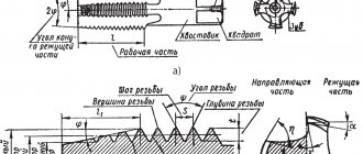
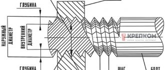
Each thread has precise geometric parameters. Metric is characterized by a triangular thread profile, which is also called fastening. It is used for parts connected to each other by screwing. The profile size is determined by its height.
The profile height (H) is the segment from the base to the top of an equilateral triangle, which is formed by a transverse section of the coil. The protrusions and depressions are made in the form of triangles with cut off vertices. In some cases, the depressions are rounded.
If the sides of each turn are mentally extended to the point of their intersection, then they will form a profile angle (α).
The main parameters indicated in the designation of a metric thread characterize its size. These include diameter and pitch. Metric thread designations indicate the main parameters.
Thread diameter is divided into 4 types:
Thread parameters such as stroke (Ph) and pitch (P) are interdependent and equal for a single-start system.
Thread stroke and pitch
The section separating the points of the same name on two turns is the thread pitch. There are main steps (large) and small steps.
Thread lead is a segment connecting two identical points on adjacent turns of the same thread. In the case where there are several entries, the move is expressed through the product of the number of steps and the number of entries.
The main thread elements also include:
- A surface inclined 45º in front of the inner or behind the outer is called a chamfer. It plays a role in connecting elements.
- Run-off is the place of transition to the uncut surface of the part. These two indicators are united by length, that is, a segment with turns, chamfer and runoff.
For metric threads, the main dimensions are summarized in tables of the relevant standards: GOST 9150-2002, GOST 8724-2002, GOST 24705-2004.
Possible structural deviations caused by the properties of materials are reported by tolerance fields, with values not exceeding the nominal profile formed by the maximum of the material. These indicators affect the accuracy of the thread fit - the density of penetration of the protrusions into the gaps.
Thread tolerance fields are divided into three accuracy classes. And also 4 types according to your preference.
DIN pipe fittings
International DIN tube fittings have a 24° tapered neck on the inside of the male fitting, which should clearly identify it as DIN if metric threads have also been identified. To determine which series and tube size a fitting is, you should examine the tube nut: most manufacturers indicate the series and tube size on the product itself. The system used for this marking combines a series of pipes with a male threaded tube, for example: the size of a 15mm tube in the L series is reduced to L15.
If the series and size are not indicated on the part, you need to match the pipe with the metric thread leader (thread size and thread pitch in mm).
Thread diameter
The conditional parameter used to designate threads in drawings and reference tables is called the nominal diameter.
If we describe an imaginary cylinder around the protrusions of the external thread and the cavities of the internal thread, then its diameter will be called external. And the designation on the drawings: D – for internal; d – for external.
The internal diameter is the size of the inscribed cylinder in the recesses of the external thread and at the points of the vertices of the internal thread, denoted by: D1 and d1 for internal and external, respectively.
The average diameter is a parameter of an imaginary cylinder whose segments are equal to ½ thread pitch. Designated: D2 and d2.
The internal diameter of the bolt is used to calculate the stress in the fastener. Its value can be taken from the table with diameters, or calculated independently based on the nominal value.
NPT thread (National pipe thread)
NPT is an American standard used for inch pipe threads. It is used, as a rule, in connections for which it is important to ensure increased tightness of pipes under conditions of exposure to high pressures (gas or liquid). The NPT thread meets the requirements established by the domestic standard GOST 6111-52 (classified as an inch conical pipe thread with a profile angle of 60 degrees).
This type of thread is characterized by the following parameters:
- designation according to profile shape:
- inch pipe cone (angle φ=3°34′48″, taper 1:16) - American standard;
- pipe inch tapered thread with a profile angle of 60 degrees - domestic standard;
- theoretical profile height (H) – 0.866025Р.
Also, in accordance with ANSI/ASME B1.20.1, cylindrical threads (NPS) also belong to this type. Within this standard there is also NPTF. Its peculiarity is the formation of a seal due to the compression of the thread at the connection point.
Inch pipe thread (American standard) (NPT) with a taper of 1:16 (cone angle φ=3°34′48″) or cylindrical (NPS) thread according to ANSI/ASME B1.20.1. The profile angle at the apex is 60°, the theoretical profile height is Н=0.866025Р. NPT thread corresponds to GOST 6111-52 - Conical inch thread with a profile angle of 60 degrees. There is also an NPTF thread - compaction occurs due to thread compression.
Tolerance fields
The fit of the outer profile into the inner one depends on the working height - the maximum amount of contact between the sides of the profiles of the connecting elements. It is expressed through thread tolerance fields.
The reliability of the connection, where fluctuations within it are minimized, is indicated by the first or exact tolerance class. The most common is the second (middle) class. The third (rough) class indicates a large deviation.
Tolerances on the dimensions of metric threads are indicated through the values of two diameters: the average and the diameter of the protrusions.
Read also: DIY crafts for your home workshop
When forming a metric thread, data is taken from the corresponding tables (GOST 16093-2004). The selection of tolerance fields is carried out according to the rules of priority:
- first priority – values indicated in bold;
- the second - in regular font;
- third – values taken in parentheses;
- extraordinary – values in square brackets (for special products).
It is possible to use tolerances that are not indicated in the tables, but are formed from the ratios of existing standard diameters.
External thread tolerance fields
Internal thread tolerance fields
It is important that the protective coatings of parts in their geometric parameters do not exceed the value of the nominal profile, therefore in such cases tolerances are used even before applying the protective layer.
Types of metric threads
Metric threads also mean all types with different profiles, measured in millimeters. These include:
- triangular thread;
- trapezoidal;
- rectangular;
- round.
In addition to the metric system for measuring parameters, the following are used:
- inch;
- modular, where the module is the ratio of the length, expressed in millimeters, to the number π;
- pitch, basic unit - pitch - the ratio of the number π to the length, expressed in inches.
Modular threads are used for worm gears in mechanical engineering, just like pitch threads. Inch and metric are fastening thread types, but can be used for transmission.
By location they are distinguished:
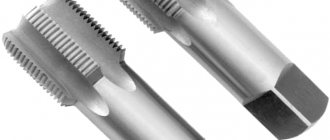
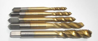
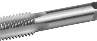
The internal thread is located in the hole, it is obtained with a tap, a specialized tool that is a rod with cutting edges.
Internal metric thread
External threads are made with a cutter or die on a rod. They can also be obtained by coasting on appropriate equipment.
External metric thread
The shape of the surface can be cylindrical or conical.
Metric conical thread is used for installation of pipelines. It is performed on surfaces where the larger diameter exceeds the small one by 16 times. Diameters vary from 6 to 60 mm.
They are also divided according to the direction of the turns into right and left. To determine the direction of the thread, it is necessary to position the part so that its axis is located away from the observer. Then, the right-hand thread is formed by a circle rotating from left to right with translational motion along the axis, and the left-hand thread, accordingly, counterclockwise.
There are different types of step sizes:
- large (with a main, large step);
- small (with small);
- special.
A large pitch is considered normal and is suitable for any materials, including fragile ones. Small allows you to withstand heavy loads, but the materials must have certain strength characteristics. Small and special ones are rarely used.
Large and fine thread pitch
The place of transition from a smooth surface to a helical one is called the approach. Based on their number, they are divided into: single- and multi-pass. The latter are also subdivided by the number of passes: two-, three- and multi-pass.
Another classification is by application. They are:
- fastening and thrust-fastening;
- kinematic or chassis;
- special purpose.
Below are the main types of metric threads and their letter designations:
- the capital letter "M" symbolizes the metric type,
- if it is made on the surface in the form of a cone, then “MK”;
- for conditions where heat resistance and strength are required, use the metric cylindrical “MJ”;
- according to ISO – “EG-M”;
- trapezoidal – “Tr”;
- persistent with an angle of inclination of one side of 30º – “S”;
- persistent reinforced - “S45”, where the number is the angle of inclination of one of the sides.
Using the caliper and pitch sensor
These devices are quite simple to operate, but with their help you can make accurate calculations faster. To do this you need:
- Determine whether the threads are conical. To use a caliper, you need to place the measuring tool points on either side of the object that is being identified. The device must be aligned on the outside of the threads at the lower end, away from the head. It displays the width. Next, you need to move the tip until it touches the threads. The readings will pop up on the display if the instrument is digital. If it is a mechanical device, you need to read the data on the sliding part. Next, you need to do a similar action on the threaded area near the screw head. If the indicator is higher near it, then you are dealing with a tapered thread. If it is parallel, then the rod does not taper.
- Tapered threads are measured on the 4th or 5th thread down from the head, essentially in the center of the threaded area. If the fastener does not become narrower, you can take measurements at any point along the entire thread. Using a support allows you to notice that there are several points where the threads are not located closely. You should not place what you want to measure within the specified intervals. It is necessary to keep your hands close to the threads.
- Press the thread pitch sensor to find the pitch. The pitch sensor has little knobs that pull out. Each of them has teeth corresponding to specific steps. You should try to insert the teeth into the threads until you find one that matches. The number for this step will be on the handle. It will be in TPI or Metric, depending on the type of pitch sensor that is used.
- Place the obtained indicators into a standardized measurement. Once the pitch is determined, the length of the screw from under the head can be calculated, and then the numerical values can be placed into a standard measurement, which is diameter, thread pitch or TPI, and length. If you are measuring a metric screw or bolt with a diameter of 4mm, a thread pitch of 0.4mm and a length of 8mm, then the measurement will be M4 X 0.4 X 8M.
Many people believe that the metric system is actually simpler because many measurements are in the same unit and there are no fractions to complicate calculations.
At the First Fasteners store you will find a wide selection of fasteners: from standard bolts and nuts to anchors and fastening systems.
Application
Metric threads are widespread in the countries of the former Soviet Union. Used for application to both internal and external planes of fasteners. Typically used for fastening metal structures of various types. For these purposes, a variety of bolts (anchor and conventional) and other types of fasteners are manufactured. She found a particular purpose in mechanical engineering, construction of engineering communications, especially in the plumbing sector. Most pipe and container fittings are manufactured with this type of thread.
Most often, this type of carving is applied to cylindrical objects. But in some cases, when it is necessary to achieve tightness, a conical shape is used. This form, with a metric thread applied, allows you to achieve maximum tightness, even without the use of additional sealing agents. Most often used for installation of pipelines.
37°/74° and flat end Chinese metric fittings
These fittings are increasingly being exported from China using heavy equipment to Chinese standards. What defines these standards is that they both use North American sealing styles, but with metric threads. This includes O-ring face sealing (ORFS) and 37° flared seat (JIC) sealing methods, however UN and SAE threads are replaced by metric threads and do not follow traditional thread pitches in all sizes.
In Russia, these fasteners are also found, but much less frequently. They are produced in Chinese factories primarily for export and sale on the North American market.
State standards
GOST 8724-2002
State standard containing standards defining the required parameters of metric threads, including pitch and diameter. Adopted in 2002, with subsequent editions, as an analogue of the international standard ISO 261-98. The GOST text practically repeats the international text, with one difference: the ISO range ranges from 1 to 300 mm, this standard has been expanded to the range from 0.25 to 600 mm. The last revision of the text was made in 2004 and is valid today.
Read also: Why chainsaw stalls at idle?
The standard contains individual parameters that can also be found in other standards. The structure of the document is similar to other standards of this type. All information is structured in the form of tables containing requirements for thread pitch and diameter. This test structure is as convenient as possible for understanding and use.
It should be noted that the regulatory information applies to threads of all types, be it left-handed or right-handed. The standard establishes the standard value of metric thread steps in the range from 0.075 to 8 mm.
The document consists of:
- Prefaces. Which contains general information about GOST, by whom and when it was adopted, when changes were made.
- Scope of application. Information is provided on the range of regulatory requirements for size and pitch.
- Links to standards.
- Definitions.
- Table of diameters and pitch. The section contains a table of standard indicators.
- Thread designation. Labeling standards are indicated.
GOST 24705-2004
The standard was adopted in 2004. Its standards apply to all types of threads in accordance with GOST 8724. The text information is also structured in the form of a table. Complies with the international standard ISO 724:1993 with additions in accordance with the exclusive requirements of each member country of the Interstate Council for Standardization.
GOST 9150-2002
A standard regulating the requirements for the profile, namely the geometric parameters. Adopted in 2002 and covering all types of threads. The text of GOST is closely related to the above standards.
GOST 16093-2004
Adopted in 2004. Regulates the standard tolerance of threads and markings, applies to different types. The latest version contains the provisions of the international standard.
The above standards are applied in combination, as they complement and refer to each other.
NPSM (National pipe thread) thread
Complies with American standard NSI/ASME B1.20.1.
This type of thread is characterized by the following parameters:
- designation according to the profile shape - inch cylindrical pipe thread (profile in the form of an isosceles triangle with an apex angle of 60 degrees);
- theoretical profile height (H) - 0.866025Р;
- Thread size range: 1/16" to 24" (in accordance with NSI/ASME B36.10M, BS 1600, BS EN 10255 and ISO 65).
Table 4
Designation of thread size NP, steps and nominal values of outer, middle and inner thread diameters, mm
| Thread size designation | Threads per inch | Thread length | Thread diameter in the main plane | |||
| Working | From the end of the pipe to the main plane | Outer d=D | Average d2=D2 | Internal d1=D1 | ||
| 1/16″ | 27 | 6,5 | 4,064 | 7,895 | 7,142 | 6,389 |
| 1/8″ | 7,0 | 4,572 | 10,272 | 9,519 | 8,766 | |
| 1/8″ | 18 | 9,5 | 5,080 | 13,572 | 12,443 | 11,314 |
| 3/8″ | 10,5 | 6,096 | 17,055 | 15,926 | 14,797 | |
| 1/2″ | 14 | 13,5 | 8,128 | 21,223 | 19,772 | 18,321 |
| 3/4″ | 14,0 | 8,611 | 26,568 | 25,117 | 23,666 | |
| 1″ | 11½ | 17,5 | 10,160 | 33,228 | 31,461 | 29,694 |
| 1.1/4″ | 18,0 | 10,668 | 41,985 | 40,218 | 38,451 | |
| 1.1/2″ | 18,5 | 10,668 | 48,054 | 46,287 | 44,520 | |
| 2″ | 19,0 | 11,074 | 60,092 | 58,325 | 56,558 | |
| 2.1/2″ | 8 | 72,699 | ||||
| 3″ | 88,608 | |||||
| 3.1/2″ | 101,316 | |||||
| 4″ | 113,973 | |||||
| 5″ | 141,300 | |||||
| 6″ | 168,275 | |||||
| 8″ | 219,075 | |||||
| 10″ | 273,050 | |||||
| 12″ | 323,850 | |||||
Designation principles
The designation of threads in drawings is carried out according to the following rules.
- Indicate with solid thin and thick lines. The designation of an internal thread is a thin line along the outer diameter and a thick line on the internal one, and an external thread is indicated by a thick line along the outer diameter and a thin line on the internal one.
- If the part is projected onto a plane along the axis of rotation, then it is shown as solid straight lines. If - across, then this is an open contour, 0.75 of the total circumference. The ends of the arc should not lie on the axes of the part in the figure.
- The gap between the thin and thick lines should be more than 0.8 mm, but less than the step size.
- When designating metric threads in drawings perpendicular to the axis, chamfers are depicted only with structural significance.
External and internal thread types
Metric threads are standardized by several documents: GOST 8724-2004, GOST 2470-2004, GOST 9150-2002, GOST 1693-2005. They specify the requirements for dimensions, profile, pitches and tolerances.
Based on the product labeling, you can determine all the necessary parameters and type. Entry includes:
- a capital letter characterizing the type, or two capital letters - a type and a subspecies (for example, metric - M; metric conical - MK);
- a number expressing the nominal diameter in millimeters (M20 - metric with a nominal diameter of 20 mm);
- in the case of a small step, indicate its value in millimeters, using the multiplication sign - M20x1.5;
- in the case of a multi-start, add an indication of the stroke after the “x” and the step in parentheses - M20x3(P1) - metric with a diameter of 20 mm, three-start, where the step is 1 mm;
- when designating a left-hand thread, the Latin capital letters “LH” are written - M20LH or M20x3(P1)LH - also only left-handed.
In some cases, the marking may include additional parameters: make-up length, tolerances and fit. Their decoding is as follows:
- indication of tolerance for external thread M12x1.75-6g and for internal thread M12-6N;
- make-up length is expressed in capital Latin letters - S - shot (short), N - normal (normal), L - long (long), sometimes a numerical value of the length in millimeters is added in parentheses if the value is non-standard; for example, M12-6g-L(30);
- the fit is expressed as a fraction through the tolerance values for internal (numerator) and external (denominator) threads, for example, taking into account how left-hand threads are designated, the general appearance will be M12x1-6H/6g-LH.
The marking may also indicate the type and number of the standard.
By choosing the right type of metric thread and its geometric parameters, you can ensure high-quality fastening of parts, long-term operation of the product and savings on repairs and maintenance.
If you find an error, please select a piece of text and press Ctrl+Enter.
Thread size M16 :
– rod diameter along the thread crest: 16 (mm); – pitch (largest): 2 (mm); – outer diameter (d): 16 (mm); – average diameter (d2): 14.701 (mm); – internal diameter along the bottom of the cavity (d3): 13.546 (mm).
Thread size M17 :
– rod diameter along the thread crest: 17 (mm); – pitch (largest): 1.5 (mm); – outer diameter (d): 17 (mm); – average diameter (d2): 16.026 (mm); – internal diameter along the bottom of the cavity (d3): 15.160 (mm).
Read also: Operating principle of a cylindrical grinding machine
Thread size M18 :
– rod diameter along the thread crest: 18 (mm); – pitch (largest): 2.5 (mm); – outer diameter (d): 18 (mm); – average diameter (d2): 16.376 (mm); – internal diameter at the bottom of the cavity (d3): 14.933 (mm).
Thread size M20 :
– rod diameter along the thread crest: 20 (mm); – pitch (largest): 2.5 (mm); – outer diameter (d): 20 (mm); – average diameter (d2): 18.376 (mm); – internal diameter at the bottom of the cavity (d3): 16.933 (mm).
Thread size M22 :
– rod diameter along the thread crest: 22 (mm); – pitch (largest): 2.5 (mm); – outer diameter (d): 22 (mm); – average diameter (d2): 20.376 (mm); – internal diameter at the bottom of the cavity (d3): 18.933 (mm).
Thread size M24 :
– rod diameter along the thread crest: 24 (mm); – pitch (largest): 3 (mm); – outer diameter (d): 24 (mm); – average diameter (d2): 22.051 (mm); – internal diameter along the bottom of the depression (d3): 20.319 (mm).
The table shows the diameters of drills and holes for cutting metric threads with large pitches .
| Thread designation | Thread pitch, mm | Diameter of drill bit for thread, mm | Diameter of thread hole with tolerance range, mm | ||||
| 4H5H; 5H; 5H6H; 6H; 7H | 6G; 7G | 4H5H; 5H | 5H6H; 6H; 6G | 7H; 7G | |||
| Nominal | Limit deviations | ||||||
| M1 | 0.25 | 0.75 | 0.75 | 0.77 | +0.04 | +0.06 | – |
| M1.1 | 0.25 | 0.85 | 0.85 | 0.87 | +0.04 | +0.06 | – |
| M1.2 | 0.25 | 0.95 | 0.95 | 0.97 | +0.04 | +0.06 | – |
| M1.4 | 0.3 | 1.1 | 1.1 | 1.12 | +0.04 | +0.06 | – |
| M1.6 | 0.35 | 1.25 | 1.25 | 1.27 | +0.05 | +0.07 | – |
| M1.8 | 0.35 | 1.45 | 1.45 | 1.47 | +0.05 | +0.07 | – |
| M2 | 0.4 | 1.6 | 1.6 | 1.62 | +0.06 | +0.08 | – |
| M2.2 | 0.45 | 1.75 | 1.75 | 1.77 | +0.07 | +0.09 | – |
| M2.5 | 0.45 | 2.05 | 2.05 | 2.07 | +0.07 | +0.09 | – |
| M3 | 0.5 | 2.5 | 2.5 | 2.52 | +0.08 | +0.1 | +0.14 |
| M3.5 | 0.6 | 2.9 | 2.9 | 2.93 | +0.08 | +0.11 | +0.15 |
| M4 | 0.7 | 3.3 | 3.3 | 3.33 | +0.08 | +0.12 | +0.16 |
| M4.5 | 0.75 | 3.75 | 3.7 | 3.73 | +0.09 | +0.13 | +0.18 |
| M5 | 0.8 | 4.2 | 4.2 | 4.23 | +0.11 | +0.17 | +0.22 |
| M6 | 1 | 5 | 4.95 | 5 | +0.17 | +0.2 | +0.26 |
| M7 | 1 | 6 | 5.95 | 6 | +0.17 | +0.2 | +0.26 |
| M8 | 1.25 | 6.8 | 6.7 | 6.75 | +0.17 | +0.2 | +0.26 |
| M9 | 1.25 | 7.8 | 7.7 | 7.75 | +0.17 | +0.2 | +0.26 |
| M10 | 1.5 | 8.5 | 8.43 | 8.5 | +0.19 | +0.22 | +0.3 |
| M11 | 1.5 | 9.5 | 9.43 | 9.5 | +0.19 | +0.22 | +0.3 |
| M12 | 1.75 | 10.2 | 10.2 | 10.25 | +0.21 | +0.27 | +0.36 |
| M14 | 2 | 12 | 11.9 | 11.95 | +0.24 | +0.3 | +0.4 |
| M16 | 2 | 14 | 13.9 | 13.95 | +0.24 | +0.3 | +0.4 |
| M18 | 2.5 | 15.5 | 15.35 | 15.4 | +0.3 | +0.4 | +0.53 |
| M20 | 2.5 | 17.5 | 17.35 | 17.4 | +0.3 | +0.4 | +0.53 |
| M22 | 2.5 | 19.5 | 19.35 | 19.4 | +0.3 | +0.4 | +0.53 |
| M24 | 3 | 21 | 20.85 | 20.9 | +0.3 | +0.4 | +0.53 |
| M27 | 3 | 24 | 23.85 | 23.9 | +0.3 | +0.4 | +0.53 |
| M30 | 3.5 | 26.5 | 26.3 | 26.35 | +0.36 | +0.48 | +0.62 |
| M33 | 3.5 | 29.5 | 29.3 | 29.35 | +0.36 | +0.48 | +0.62 |
| M36 | 4 | 32 | 31.8 | 31.85 | +0.36 | +0.48 | +0.62 |
| M39 | 4 | 35 | 34.8 | 34.85 | +0.36 | +0.48 | +0.62 |
| M42 | 4.5 | 37.5 | 37.25 | 37.3 | +0.41 | +0.55 | +0.73 |
| M45 | 4.5 | 40.5 | 40.25 | 40.3 | +0.41 | +0.55 | +0.73 |
| M48 | 5 | 43 | 42.7 | 42.8 | +0.45 | +0.6 | +0.8 |
| M52 | 5 | 47 | 46.7 | 46.8 | +0.45 | +0.6 | +0.8 |
Threaded holes
Table of drills for holes for cutting cylindrical pipe threads.
Wrench nut sizes
Basic spanner dimensions for hex bolt heads and hex nuts.
G and M codes
Examples, description and interpretation of L and M codes for creating control programs on CNC milling and lathes.
Thread types
Types and characteristics of metric, pipe, thrust, trapezoidal and round threads.
Drawing scales
Standard scales for images of parts on mechanical engineering and construction drawings.
Cutting modes
Online calculator for calculating cutting conditions during turning.
Threaded holes
Table of drills and holes for cutting metric threads with large (main) pitch.
CNC machines
Classification of CNC machines, CNC machines for metal for turning, milling, drilling, boring, threading, reaming, countersinking.
Cutting modes
Online calculator for calculating cutting conditions when milling.
Drawing formats
Table of side sizes of main and additional formats of drawing sheets.
CAD/CAM/CAE systems
CAD computer-aided design systems, 3D programs for design, modeling and creation of 3D models.
Kobelco and Komatsu fittings
Kobelco fittings are essentially the same as 24° DIN metric pipe fittings, however all Kobelco thread sizes are 1.5mm pitch. All pipe accessories for Kobelco fittings are L series and are completely interchangeable. However, there are some sizes that are truly unique to Kobelco.
Komatsu fittings have a thread pitch of 1.5 mm in all sizes and seals through a 30°/60° cone seat. If they are identified as a metric nose cone thread, extreme care must be taken to discern whether it is actually a 30°/60° (Komatsu) cone seat instead of a 37°/74° (GB Chinese) seat.