Home / Consumables
Back
Reading time: 3 min
1
9636
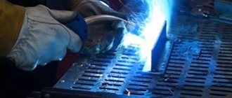
To start welding, you need the machine itself, accompanying materials, terminals, and wire at hand.
To start the process, you need to plug in the unit and create as long as you have the desire and inspiration to work. And related materials can run out at the most inopportune moment.
To avoid such unpleasant surprises, you need to know the relationship between the number of consumables and the amount of work.
It is necessary to calculate the expected consumption in advance. Each welder, before taking on an object, calculates everything down to the smallest detail and gives the customer an estimated cost.
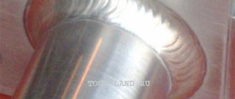
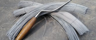
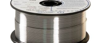
Welding wire is sold in coils or reels. Sometimes it is treated with a solution to increase shelf life.
In our review, we will tell you in detail how to calculate the wire footage and show it clearly in the calculations.
- Wire specifics
- Wire consumption
- How to make a calculation
- Example
- Summarize
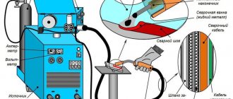
Calculation of welding wire consumption per meter of seam
Even novice welders know that during welding work various components are used, such as wire or electrodes.
And if to operate a welding machine you only need access to electricity and can work endlessly, then components tend to run out. To ensure that materials do not run out at the most inopportune moment, their quantity can be pre-calculated.
This is especially useful during repairs, since it is possible to calculate the cost of welding work and tell the customer the exact price.
In this article we will explain in detail how to calculate the wire, give an example of the calculation and tell you about all the features.
Wire Features
Before calculating the consumption of welding wire, familiarize yourself with all the features of the filler material used in the work. First of all, the wire may have a different deposition rate, which significantly affects the final figures in the calculation.
If you use wire for welding with automatic or semi-automatic welding equipment, then calculating the consumption of welding components is simply necessary. When using argon arc welding, this is not necessary, but it won’t be superfluous either.
Since with these types of welding it is recommended not to interrupt the welding seam, and this can only be achieved after accurately calculating the amount of wire. It is better to know in advance the consumption of welding wire when welding with a semi-automatic machine than to correct mistakes later. There is such a thing as a material consumption rate.
At the same time, the norm includes not only the amount of wire, but also its overuse in case of welder errors or unforeseen circumstances. When calculating, all stages of welding are taken into account: from preparatory to final. This can be compared to a construction estimate.
Knowing the required amount of, say, brick, you know in advance how tall and thick the walls will be. Let's talk in more detail about the consumption standards for welding materials.
Consumption rates
For gas or argon-arc welding, there are wire consumption standards that are prescribed in regulatory documents. They were not taken out of thin air, but were calculated based on the existing experience accumulated by professional welders.
Each type of welding and type of wire has its own physical and chemical properties that must be taken into account when calculating, so it is impossible to give exact figures for material consumption for all welds at once. However, there are approximate general values, which you can see in the table below.
The table is for informational purposes only, do not take these numbers seriously, carry out the calculations yourself.
Most often, the consumption of welding wire per 1 meter of seam is calculated. This is very convenient because you can easily and quickly make subsequent calculations to increase or decrease the amount of material for the seam. On the Internet you can easily find a calculator for the consumption of welding materials, which will simplify the calculations. But we recommend learning how to calculate the amount of wire yourself.
How to calculate consumption
The consumption of welding materials for argon-arc welding or the consumption of wire for semi-automatic welding per meter of seam is made according to the following formula:
N = G*K
Where “N” is the desired parameter or, in other words, the rate of wire consumption per 1 meter, which we need to calculate. “G” is the mass of deposit on the finished weld, again one meter long.
And “K” is the correction factor, which depends on the mass of the deposited material to the metal consumption required for welding.
To find out the value of G (weight of deposit on a welded joint), we need this formula:
G = F*y*L
The letter "F" indicates the cross-sectional area of the joint in square meters. The letter “y” is the density of the metal from which the wire is made.
Note! "y" value is extremely important because each brand of wire can vary significantly in weight due to the metal used to make it.
The value “L” is automatically replaced by the number 1, since we are calculating exactly 1 meter. If you need to calculate more or less than a meter, then use a different figure.
Using these formulas, you can calculate the wire consumption during bottom welding.
For other welding methods, you need to multiply “N” “K” , other than 1.
"K" value changes according to the position:
- In the lower position, “K” is equal to the number 1
- With semi-vertical - 1.05
- When vertical - 1.1
- With ceiling - 1.2
If you are welding metal using a semi-automatic machine, consider the shielding gas used in the work, the characteristics of your welding machine, the diameter of the wire and the features of the parts.
Thanks to these simple calculations, you can easily find out the amount of wire needed to weld parts when using argon arc welding or any other type of welding work. Take into account all the features of the type of welding and the wire used so that the calculations are accurate.
Calculation example
To better understand the calculation principle, let's give an example. So, what will be the consumption of filler wire during semi-automatic welding if ordinary steel is used as the welded metal? Let's start by calculating the weight of the surfacing; the formula G = F*y*L .
G=0.0000055 (m2) * 7850 (kg/m3) * 1 (meter) = 0.043 kg
After this, you can begin to calculate the main value using the formula N=G*K
N = 0.043 * 1 = 0.043 kg
Please note that welding is performed in the down position. This means that the correction factor is equal to one, but the final value does not change.
Instead of a conclusion
Now you know how to calculate and find out the consumption of welding wire when welding semi-automatically or for any other type of welding. Don't think this skill won't be useful to you. On the contrary, it opens up new opportunities for you. Share this material on social networks to help other novice welders. We wish you good luck in your work!
[Total: 6 Average: 2.3/5]
Factors affecting electrode consumption
Arc welding with molten metal fills the gap between the parts. To create a reliable connection, use a sufficient number of electrodes. Preliminary calculation is needed not only to take into account the costs of purchasing consumables. The performed technological operation changes the weight of the structure. In some situations, this parameter increases by 1-1.5% compared to the original value.
The consumption of electricity, electrodes and protective gases (fluxes) depends on the cross-section of the seam. But we must take into account the loss of metal due to evaporation and splashes. The resulting slag also does not perform useful functions. Part of the electrode (40-60 mm) is needed only for fastening in the holder. When creating several connections, the consumption of materials is greater than when welding 1 long seam.
For correct calculation it is necessary to take into account:
- welding duration;
- seam depth;
- the amount of material needed to create a strong connection;
- features of the technological process.
To calculate, you need to take into account the welding duration and the depth of the seam.
Departmental construction standards for calculating the consumption of electrodes are established by a special document (see VSN 452-84 dated December 14, 1984). These rules are created using analytical and laboratory techniques.
The tabular data takes into account losses on such positions as:
- sharpening and cinders of electrodes;
- fumes;
- formation of slags;
- splashing;
- remainder in the coil (for wire);
- melting of the flux.
The document's developers note the possibility of revising standards in the event of technology changes or when working with new and non-standard consumables.
Calculation of consumption of welding materials
| Plate thickness, t, mm | Gap between welded edges, s, mm | Volume of electrolytic coating per meter, v, cm3/m | Electrolytic coating weight per meter, v, kg/m |
| 1 | 0 | 2 | 0,02 |
| 1,5 | 0,5 | 3 | 0,02 |
| 2 | 1 | 4 | 0,03 |
| 3 | 1,5 | 7 | 0,05 |
| 4 | 2 | 22 | 0,17 |
| 5 | 2,5 | 25 | 0,20 |
| 6 | 3 | 32 | 0,25 |
| 7 | 3 | 42 | 0,33 |
Fillet weld
| Plate thickness, t, mm | Profile size, s, mm2 | Volume of electrolytic coating per meter, v, cm3/m | Electrolytic coating weight per meter, v, kg/m |
| 2 | 4 | 6 | 0,05 |
| 2,5 | 6,5 | 8,5 | 0,07 |
| 3 | 9 | 12,5 | 0,10 |
| 4 | 16 | 21 | 0,16 |
| 5 | 25 | 31,5 | 0,25 |
| 6 | 36 | 42 | 0,33 |
| 7 | 49 | 57 | 0,45 |
| 8 | 64 | 73,5 | 0,58 |
| 9 | 81 | 94 | 0,74 |
| 10 | 100 | 114 | 0,89 |
| 11 | 121 | 138 | 1,08 |
| 12 | 144 | 162 | 1,27 |
| 13 | 169 | 190 | 1,49 |
| 14 | 196 | 224 | 1,76 |
| 15 | 225 | 248 | 1,95 |
External corner
| Plate thickness, t, mm | Profile size, s, mm2 | Volume of electrolytic coating per meter, v, cm3/m | Electrolytic coating weight per meter, v, kg/m |
| 2 | 2 | 3,5 | 0,03 |
| 3 | 4,5 | 7,5 | 0,06 |
| 4 | 8 | 10,5 | 0,08 |
| 5 | 12,5 | 16 | 0,13 |
| 6 | 18 | 22 | 0,17 |
| 7 | 24,5 | 31,5 | 0,25 |
| 8 | 32 | 40,5 | 0,32 |
| 9 | 40,54 | 51 | 0,40 |
| 10 | 50 | 64 | 0,50 |
| 12 | 72 | 93 | 0,73 |
| 15 | 113 | 141 | 1,11 |
| 18 | 162 | 204 | 1,60 |
| 20 | 200 | 252 | 1,98 |
| 22 | 242 | 204 | 2,39 |
| 25 | 323 | 405 | 3,18 |
V-joint
| Plate thickness, t, mm | Gap between welded edges, s, mm | Volume of electrolytic coating per meter, v, cm3/m | Electrolytic coating weight per meter, v, kg/m |
| 4 | 1 | 11,5 | 0,09 |
| 5 | 1 | 16,5 | 0,13 |
| 6 | 1 | 23 | 0,17 |
| 7 | 1,5 | 33,5 | 0,26 |
| 8 | 1,5 | 33,5 | 0,26 |
| 9 | 1,5 | 51 | 0,38 |
| 10 | 2 | 66,5 | 0,49 |
| 11 | 2 | 78,5 | 0,56 |
| 12 | 2 | 91 | 0,65 |
| 14 | 2 | 120 | 0,86 |
| 15 | 2 | 135 | 0,97 |
| 16 | 2 | 151 | 1,04 |
| 18 | 2 | 189 | 1,33 |
| 20 | 2 | 227 | 1,63 |
| 25 | 2 | 341 | 2,46 |
| Plate thickness, t, mm | Gap between welded edges, s, mm | Volume of electrolytic coating per meter, v, cm3/m | Electrolytic coating weight per meter, v, kg/m |
| 4 | 1 | 13 | 0,10 |
| 5 | 1 | 19,5 | 0,15 |
| 6 | 1 | 27 | 0,20 |
| 7 | 1,5 | 39 | 0,30 |
| 8 | 1,5 | 49 | 0,37 |
| 9 | 1,5 | 60,5 | 0,44 |
| 10 | 2 | 77,5 | 0,57 |
| 11 | 2 | 92 | 0,66 |
| 12 | 2 | 107 | 0,77 |
| 14 | 2 | 141 | 1,02 |
| 15 | 2 | 160 | 1,15 |
| 16 | 2 | 180 | 1,23 |
| 18 | 2 | 223 | 1,60 |
| 20 | 2 | 271 | 1,94 |
| 25 | 2 | 411 | 2,94 |
| Plate thickness, t, mm | Gap between welded edges, s, mm | Volume of electrolytic coating per meter, v, cm3/m | Electrolytic coating weight per meter, v, kg/m |
| 4 | 1 | 15 | 0,13 |
| 5 | 1 | 22,5 | 0,19 |
| 6 | 1 | 31 | 0,29 |
| 7 | 1,5 | 45 | 0,38 |
| 8 | 1,5 | 57 | 0,47 |
| 9 | 1,5 | 70 | 0,59 |
| 10 | 2 | 90 | 0,76 |
| 11 | 2 | 107 | 0,89 |
| 12 | 2 | 125 | 1,05 |
| 14 | 2 | 165 | 1,34 |
| 15 | 2 | 188 | 1,55 |
| 16 | 2 | 211 | 1,75 |
| 18 | 2 | 263 | 2,17 |
| 20 | 2 | 320 | 2,62 |
| 25 | 2 | 488 | 4,00 |
| Plate thickness, t, mm | Gap between welded edges, s, mm | Volume of electrolytic coating per meter, v, cm3/m | Electrolytic coating weight per meter, v, kg/m |
| 4 | 1 | 17,5 | 0,14 |
| 5 | 1 | 26 | 0,22 |
| 6 | 1 | 36 | 0,30 |
| 7 | 1,5 | 51,5 | 0,44 |
| 8 | 1,5 | 65,5 | 0,55 |
| 9 | 1,5 | 81,5 | 0,69 |
| 10 | 2 | 104 | 0,86 |
| 11 | 2 | 124 | 1,02 |
| 12 | 2 | 145 | 1,23 |
| 14 | 2 | 193 | 1,60 |
| 15 | 2 | 219 | 1,81 |
| 16 | 2 | 245 | 2,02 |
| 18 | 2 | 308 | 2,51 |
| 20 | 2 | 376 | 3,11 |
| 25 | 2 | 577 | 4,76 |
GO TO ELECTRODE CATALOG
Welding electrodes Orlovskie MR-3S (5kg) d 4.0Electrodes MR-3S (they are also called “Blue”) are the most...
747.50 rub. Wholesale price: 105.00 rub/kg
Welding electrodes Special electrode UONI 13/55 (5kg) d 4.0 A good welder will always be in demand, but...
455.00 rub. Wholesale price: 81.00 rub/kg
Copper-plated welding wire SV08G2S (ER70S-6) FARINA (made in China) d 1.2 coils 15 kg (row)..
RUB 1,785.00 Wholesale price: 106.00 rub/kg
Galvanized welded mesh (Euro fence) coated with powder paint (green) Gitter (gitter) 50*200 (3..
960.00 rub. Wholesale price: 880.00 rub/piece
Counting Features
The information presented is used to calculate costs for welding work.
The final result is influenced by the following factors:
- connection type;
- thickness, clearance, relative position of parts;
- ease of access;
- brand of electrodes;
- current values.
The final result is influenced by the type of connection.
The calculation method is chosen taking into account the characteristics of technological operations.
Per ton of metal structures/reinforcement
When performing large-scale work, tabular data on consumption per ton of metal (Kr) is used. This standard indicator is established taking into account the parameters noted above. Select the position corresponding to the type of electrode. By multiplying by the mass of the structures, the amount of consumables is obtained. They add a margin for errors and other associated losses. Converting to pieces for such volumes does not make practical sense.
For 1 m seam
For calculations, you can apply the considered formulas and test results. To simplify calculations, use tabular data. Below is information on the standard consumption in kilograms per 1 m of welded joint.
This example uses a backing with 1 beveled edge.
| Thickness of parts, mm | Vnm, kg | Electrode group | ||||
| II | III | IV | V | VI | ||
| 3 | 0,232 | 0,411 | 0,438 | 0,466 | 0,493 | 0,521 |
| 5 | 0,384 | 0,680 | 0,724 | 0,77 | 0,816 | 0,861 |
| 8 | 0,832 | 1,474 | 1,573 | 1,671 | 1,769 | 1,868 |
| 12 | 1,562 | 2,765 | 2,949 | 3,133 | 3,318 | 3,502 |
If pipes are welded
As in the previous example, instead of calculations using formulas, it is more convenient to use prepared standards. The information in the table is presented for similar initial conditions: only 1 edge of the joint is beveled, a lining is left that prevents the penetration of molten metal into the structure. Consumption is given in kg.
| Pipe dimensions (diameter x wall thickness), mm | Vnm | Electrode group | ||||
| II | III | IV | V | VI | ||
| 57x3 | 0,041 | 0,072 | 0,077 | 0,082 | 0,087 | 0,091 |
| 89x6 | 0,128 | 0,227 | 0,242 | 0,27 | 0,272 | 0,288 |
| 133x6 | 0,193 | 0,342 | 0,365 | 0,388 | 0,410 | 0,433 |
| 159x8 | 0,482 | 0,724 | 0,772 | 0,820 | 0,869 | 0,917 |
For 1 kg of surfacing
Some manufacturers indicate in the accompanying documentation the value of the deposition coefficient (KN) for the selected type of consumables when working with the recommended current range.
| Electrode brand | Kn, g/A*h | Consumption of electrodes per kilogram of deposited metal, kg |
| OZS-6 | 8,5-10,5 | 1,5 |
| EA-395/9 | 10-11,5 | 1,6 |
| UONI-13/55 | 9-10 | 1,6 |
Welding wire consumption during semi-automatic welding - Metalworker's Handbook
Semi-automatic welding in carbon dioxide is a high-quality and at the same time relatively inexpensive method of joining metal workpieces. Semi-automatic welding in carbon dioxide is most often used in cases where there is a need for reliable joining of metal parts of products of different thicknesses.
In addition, this type of welding procedure is in demand in situations where thorough cleaning of the parts being joined is impossible for one reason or another.
Advantages and disadvantages
According to GOST, semi-automatic welding in carbon dioxide involves the use of direct current of direct polarity, since with the opposite indicator it is not possible to obtain arc stability.
Direct current is also suitable for the case when welding is carried out using the metal deposition method, while ensuring greater efficiency of the procedure.
Despite the fact that carbon dioxide is noticeably inferior in its protective properties to other gases (argon, in particular), it is nevertheless excellent for processing most standard industrial metals.
This is explained not only by the low cost of carbon, which allows us to consider this welding option as a budget option, but also by safer conditions for storing and directly using the material.
Other advantages of semi-automatic welding in a carbon dioxide environment include:
- high quality of the resulting connections (with a minimum of defects), combined with low cost of consumables and high productivity;
- the ability to weld workpieces in a suspended state (without lining);
- admissibility of fusion of products of small thickness;
- more efficient use of welding arc energy compared to argon arc welding.
All of the listed advantages of carbon dioxide must be taken into account along with problem areas associated with the layer-by-layer method of forming a seam and its porosity due to poor-quality fusion. This kind of welding has low efficiency.
This kind of welding has low efficiency. This is explained by the fact that working in a carbon dioxide environment requires lengthy preparation of equipment for startup.
It is strictly forbidden to use carbon dioxide in poorly ventilated or enclosed areas, since its vapors in the air can lead to asphyxia (suffocation).
Areas of use
Arc processing of metals in carbon dioxide and the semi-automatic welding machine used for this are mainly in demand when it is necessary to obtain simple joints of workpieces. Carbon dioxide welding technology is widely used in the following areas:
- during the construction of capital objects (bridges, overpasses and similar structures mounted on the basis of frame metal structures);
- in factory conditions and in workshops whose work profile is related to the manufacture of metal products or their repair (at service stations, in particular);
- during the construction of welded truss structures for agricultural purposes;
- in country and private farms (in the manufacture of fences, gates, wickets, permanent greenhouses).
In other words, the relatively simple and reliable method of gas welding, as well as the carbon dioxide semi-automatic machine itself, are in demand wherever it is necessary to process metal products of various profiles with high quality and quickly.
Carbon dioxide consumption
Despite the fact that the amount of carbon dioxide consumed during welding is standardized taking into account many different factors, they can all be reduced to several points.
This value depends on the speed of movement of the wire in the semi-automatic machine, which in turn is determined by the parameters of the consumable material itself.
The flow rate is influenced by the quality of the flux used and the pressure under which the gas is supplied to the place of its direct use. Depending on these factors, the flow rate can vary from 3 to 60 liters per minute.
An approximate calculation of the consumption indicator can be carried out independently, taking into account a number of circumstances. Firstly, it should be taken into account that carbon dioxide consumption only at the preparatory stage will be at least 10% of the total.
Secondly, it is necessary to know the specific consumption value for carbon dioxide (the volume required to prepare one seam). In addition to these factors, the calculations must take into account both the thickness of the melting wire and the corresponding parameter of the metal workpieces being processed.
Let's add to this that a standard cylinder holds about 25 kilograms, and that from each kilogram of gas after a chemical reaction, approximately 500 liters of gas are formed (specified in GOST 8050-64).
Based on the initial data after summation, it turns out that one cylinder of carbon dioxide is enough to work non-stop for approximately 15 hours.
Often, when working with a semi-automatic welder, a welder has to use a special flux-cored wire, the contents of which replace carbon dioxide. In this case, the corresponding calculations are carried out using completely different methods.
The calculated data can be viewed in the table.
| Thickness, mm | Wire diameter, mm | Current value, A | Voltage, V | Wire feed speed, m/h | Gas consumption |
| 1,5 | 0,8 | 120 | 19 | 150 | 6 |
| 1,7 | 1 | 150 | 20 | 200 | 7 |
| 2 | 1,2 | 170 | 21 | 250 | 10 |
| 3 | 1,4 | 200 | 22 | 490 | 12 |
| 4-5 | 1,6 | 250 | 25 | 680 | 14 |
| 6 or more | 1,6 | 300 | 30 | 700 | 16 |
Features of work
The semi-automatic welding process in a protective carbon dioxide environment can be classified as a relatively simple operation. It does not require special skills or any excessive effort. The welder must carefully ensure that the so-called “stick out” of the wire, which determines the welding mode, is normal.
Each welding machine operating in semi-automatic mode differs in the value of this indicator, which must also be taken into account by the contractor.
In addition, the welder needs to ensure that the special torch included in the welding equipment kit moves evenly along the seam being formed.
A number of recommendations have been developed that must be followed when handling carbon dioxide in semi-automatic welding mode, the main ones are as follows.
First of all, before starting the metal processing process, you should make sure that the tool is in working order, and that carbon dioxide is supplied to the burner at the required pressure (0.02 kPa).
The value of this indicator for carbon dioxide (as well as the argon pressure during corresponding welding) can be adjusted using a reducer built into it.
During operation, the burner must be positioned at a certain angle to the seam line (as a rule, this figure is taken to be approximately 65-75 degrees). In this case, the direction of its formation should be from right to left, which provides a better overview of the metal edges formed during welding.
If it is impossible to achieve the required quality of the weld, you must try to change the operating mode of the machine (adjust the parameters of the supply current and arc voltage or change the feed speed of the filler wire).
Optimal choice
Semi-automatic welding using carbon dioxide, despite the significant gas consumption and its danger, is one of the optimal approaches to forming a truly high-quality joint.
How to count by piece
To calculate the number of electrodes, you can use the basic formula N=Vnm*K and a table of correction factors.
The weight of the deposited metal is taken from the table:
| Compound | Parts Thickness/Gap (mm) | Vnm, g/m |
| Ceiling | 4/2 | 70 |
| 7/3 | 130 | |
| 6/2,5 | 140 |
Apply a coefficient that corresponds to the selected type of electrode. The calculation result is multiplied by the length of the seam and divided by the weight of 1 product.
In the following example, for 1-pass welding of workpieces 1.5 mm thick, OZL 6 electrodes with a diameter of 4 mm and a length of 450 mm are used. The length of the seam is 8 m. A vertical joint is created with smooth edges with an initial gap of 0.5 mm.
An algorithm is used to calculate the number of electrodes.
Calculation algorithm:
- subject to standard technology, take 0.02 kg per meter of connection, which in total for the specified length is 0.16 kg = 0.02 * 8;
- when working with OZL-6 electrodes, a correction factor of 1.6 is used;
- get the total weight of consumables (0.16-1.6=0.256 kg);
- taking into account the typical weight of 1 product (58 g), calculate the consumption in pieces (256/58 = 4.4);
- make a reserve to take into account possible errors 4.4*1.08=4.45;
The resulting value is rounded up, which allows you to find out the number of electrodes to create the corresponding welded structure. It is equal to 5 pcs.
Welding wire: consumption, threading, feeding
Wire ESAB OK AristoRod 12.50. Photo 220Volt
To perform one-time welding work at home, you need to decide on the amount of consumables that will need to be purchased in the store. In industrial conditions, the amount of welding wire consumed will affect the final price of the product produced and, ultimately, customer demand.
Wire consumption rates
The presence of wire consumption standards, which are presented as the amount of consumable material in units of mass per linear meter of weld , allows you to navigate the amount of wire to perform a specific type of welding work. With a mechanized welding method (automatic, semi-automatic, common argon-arc welding technology), the consumption rates are significantly less than with manual welding.
Table of material consumption per meter of seam when welding with semi-automatic welding
Edge cutting options
When developing a welding process, recommendations are given on the cutting of edges and gaps in the welded joint. They are based on the design documentation base, where the dimensions of the workpieces and the type of welded joint (lap, butt, corner, etc.) are determined.
Further, in state and industry standards and technical conditions for welded joints, the required dimensions of the weld are found. Calculating the theoretical cross-sectional area with modern computer technology is not difficult.
Such calculations are especially in demand in the construction industry , where welding work is carried out in large quantities and it is necessary to have a good understanding of the varied quantities and range of consumables.
In the document VSN 416-81 “General production standards for the consumption of materials in construction” in the section “Welding work” the consumption standards for welding materials are given.
These standards, depending on the type of work, are presented in tables by type of connection.
An example of one of the tables for mechanized butt welding in carbon dioxide for a one-sided butt joint without beveled edges:
Table. Standards for 1 meter of seam.
| Line code | Thickness of parts, mm. | Carbon dioxide, kg. | Welding wire, kg. |
| 01 | 1,0 | 0,027 | 0,05 |
| 02 | 2,0 | 0,049 | 0,091 |
| 03 | 3,0 | 0,052 | 0,099 |
| 04 | 4,0 | 0,056 | 0,105 |
| 05 | 5,0 | 0,085 | 0,161 |
| 06 | 6,0 | 0,09 | 0,17 |
Here it should be taken into account that the consumption rates are given for a seam located in the lower position . In other situations, according to document VSN 416-81, a correction is applied in the form of the following coefficients:
- vertical position – 1.12;
- horizontal position – 1.13;
- ceiling - 1.26.
Gas consumption rates are calculated in the table when supplied with a specific flow rate of 6 l/min. If the feed is increased, then correction factors are introduced accordingly:
- for 8 l/min – 1.3;
- for 10 l/min – 1.6;
- for 12 l/min -2.0.
Important! All normative data are theoretical. In reality, it is necessary to take into account the work associated with preparatory welding operations (performing tack welds, temporary welds, etc.), additional consumption of welding wire when the arc is interrupted, sealing minor defects, dependence on the qualifications of the welder, and others. Therefore, you should always make a reserve, based on the experience of specialists.
Carbon dioxide consumption per 1 kg of material
Semi-automatic welding of stainless steel indoors
The consumption of carbon dioxide should not be less than a certain level, after which the quality of the weld will begin to decrease. But large expenditures are not economically feasible. The choice of the optimal value depends on the thickness of the workpieces being welded, the diameter of the wire and the value of the welding current.
The factor of the place where welding is performed is also taken into account . When welding in the open air, the gas evaporates faster and the flow rate should be increased. This is especially true when there is strong movement of air masses (wind).
It is necessary to monitor the purity of the gas . Gas consumption is influenced by the quality of the gas mixture.
The qualifications of the welder greatly influence gas consumption .
Calculation: formula
When performing a one-time job, you can independently calculate the approximate wire consumption. By increasing the resulting result by the technological losses required in the work, you will receive a guaranteed supply of welding wire for welding work.
The calculation is carried out using the formula N=G*K ,
- where N is the wire consumption rate;
- G – mass of deposited metal in the weld;
- K is a coefficient that takes into account the increased consumption of material to create the existing surfacing.
To calculate the mass of the deposited metal, the most difficult thing will be to accurately determine the cross-sectional area (F) of the deposit. Here you will need to use formulas from geometry to calculate the areas of various figures.
The density (γ) of the deposit depends on the type of material of the welding wire. The formula F*γ is used to find the mass (G) of surfacing for 1 meter of weld. The K coefficient depends on the spatial position of the weld, the shielding gas used and other features of the parts. This calculation will make it possible to avoid wasted time during welding work.
Material feeding mechanism
The feed mechanism is responsible for a stable supply to the welding zone, in accordance with the specified parameters in the semi-automatic machine . It allows you to adjust the wire feed speed over a wide range of values.
Semiautomatic welding machine Blue Weld MEGAMIG 500S with wire feed mechanism. Photo VseInstruments.ru
Depending on the design of the semi-automatic device, the mechanism can be located both inside the device body and outside it.
- If the mechanism is located in the housing, the operating principle is based on pushing the wire into the welding zone. The consumable material is transferred to the burner nozzle through a flexible metal channel, as a result of which there are restrictions on the length of such a guide device.
- The mechanism can be located on the burner itself . Then he will perform a pulling action, pulling the wire towards himself. The advantages of this method are the use of sleeves of sufficiently long length. However, a welding head with increased weight and dimensions creates significant inconvenience in the work of the welder.
- Feed mechanisms with a combined design have a right to exist, but are used extremely rarely.
The principle of operation of the mechanism is based on the feeding of wire pressed between rotating rollers. The main components of the mechanism are as follows:
- a stationary roller, which can only carry out rotational movements; the grooves on the roller are made in accordance with the diameter of the wire being pulled;
- a roller with a movable axis connected to a clamping device and mirror-image grooves located on the stationary roller;
- a clamping device that regulates the pressure on the wire;
- an electric drive with a worm gear drives a stationary roller;
- an electronic circuit that controls the parameters (change of feed rate, interruption for a given period of feed time, etc.) of the device;
- guide bushings with a diameter slightly larger than the diameter of the wire, installed before and after the device.
To create a more uniform pressure on the wire, a mechanism with four rollers, arranged according to the 2 x 2 principle, is used.
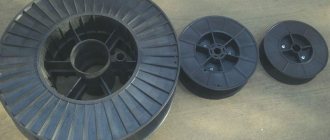
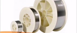
Reels and reel seats
Aluminum welding wire ER4043 (1.6 mm; spool 6 kg) ELKRAFT 93614. Photo AllInstruments.ru
Welding wire is wound onto reels, from which it is removed during operation. The reel is securely secured in semi-automatic machines using devices called reel holders. The devices for fastening the reels must correspond to those on the reel seat.
When the semi-automatic machine is turned off, the coil of wire tends to continue its movement, which can lead to the formation of loops on the wire. The design of the reel seat has a braking device , for example, in the form of a friction clutch. Adjusting it with a nut prevents the spool from unwinding freely and maintains the correct winding of the wire.
How to refuel, installation on automatic and semi-automatic
How to thread welding wire into a semi-automatic machine is shown in the video. Here it is worth noting the key points that the author draws attention to.
- When putting on a new cassette, be sure to hold the end of the wire to prevent the coil from unwinding.
- The wire should fit into the groove of the roller.
- For pulling, use the electric drive idling (without gas supply) at the highest feed speed.
- Avoid getting caught in the sleeve or current collector.
The author of the video did not mention anything about adjusting the clamping device. The use of cored wire requires special attention. For welding with less spatter, a four-roll feed mechanism is recommended for flux-cored wire to better distribute the clamping force.
Where can I buy
The sale of various types of consumables is carried out by companies collected in a separate section. Familiarization with the information presented will allow you to find out where to buy welding wire.
In addition to the possibility of purchasing products from suppliers, it is also recommended to familiarize yourself with the range offered by manufacturers. Leading global enterprises, for example, ESAB and DEKA, have a wide network of representative offices, which allows you to purchase consumables and be completely confident in the quality of the products.
Sections: Welding wire
alloy welding wires, copper welding wire, flux-cored welding wires, wire for argon arc welding, aluminum welding wire, copper-plated welding wire, polished welding wire, steel welding wire, stainless steel welding wire, titanium welding wire
Differences in theoretical and practical calculations
For a quick calculation, you can use the simple formula N=Bnm*K, where:
- N – standard consumption in kg;
- Vnm – weight of the deposited metal layer;
- K – reference coefficient for consumption using standard technologies.
To calculate the flow rates of the electrodes, a simple formula is used.
Additional amendments are applied taking into account the specifics of work processes. For manual arc welding (with covered electrodes), a multiplier of 0.826 is used. This value is suitable for calculating the connection in a rotary joint. If pipes are welded, you need to take K = 1.23. In this example, the relative position of the parts is assumed to be at an angle of 45°.
For calculations, a basic flow coefficient of 1.4 is used.
Below are the correction factors for individual brands of electrodes:
- 1.5 (II group) – OZL-5 (E6 and 25B), TsT-28;
- 1.6 (III) – OZL-2 (3, 6, 7, 8 and 21), ZIO-8, TsL-17;
- 1.7 (IV) – OZL-9A, TsL 9 (11), TsT-16, GS-1;
- 1.8 (V) – OZL-20 (22), OZS-11, NZh-13;
- 1.9 (VI) – OZL 27 (28), ANZHR-2.
Simplify calculations using reference standards. This data is available in thematic industry rules and federal GOSTs. The summary information is divided into groups according to types of electrodes, welding technologies, and other parameters. Typical values are substituted into the calculation formulas.
A practical way is to create a test seam.
A practical method involves creating a test seam in a control area.
This method allows you to find out the consumption of materials with high accuracy.
The following algorithm is used:
- fix the workpieces at an angle and with gaps established by the design specifications;
- create conditions that will be maintained during work operations;
- adjust the current strength;
- after welding, the length of the control section and the electrode cinder are specified.
You should repeat the above steps at least 3 times. Particular attention is paid to the identity of processes. In addition to the position of the electrode, they ensure a constant temperature in the room. Gusts of wind and other external influences that can impair the accuracy of the experiment are excluded. The obtained data is used to calculate the average flow rate.
We recommend reading Features and main advantages of using E46 electrodes
Possible errors
The limited accuracy of analytical techniques and calculations based on test welding should be objectively assessed.
Calculation of electrode consumption may have an error.
Each method implies compliance with standard conditions that cannot be reproduced without deviations when performing work operations. It is possible that there may be defective products in the shipment. Taking into account the noted features, it is recommended to increase the calculation result by 5-8%.
Number of electrodes in a pack of 1 kg
The standard information label on the packaging box contains the following information:
- name of the product (brand of electrodes);
- diameter and length;
- total weight;
- intended purpose (the ability to create vertical, inclined, horizontal and ceiling joints);
- recommended range of welding currents;
- article and lot number;
- production date;
- information about standards and official approvals;
- manufacturer identification parameters.
The standard information label contains information about the electrodes.
Current GOST limits only the maximum weight of a pack depending on the diameter.
When creating electrodes, the rod material and the thickness of the surface layer are standardized.
The data on the weight parameters of individual products given in the table may differ by ±2 grams without violating the standard.
| External diameter (length), mm | Weight | |
| Packaging (permissible), kg | Electrode, g | |
| 3 (350) | 5 | 26 |
| 4 (450) | 5 | 58 |
| 5 (450) | 8 | 82 |
If the total weight is 4 kilograms, using tabular data it is easy to calculate the number of 3 mm electrodes: 4000/26 ≈ 154 pcs. We should not forget that the data given correspond to products with a length of 450 mm.
Normal consumption
Standard indicators are given in the mentioned document VSN 452-84.
The standards are developed taking into account the specifics of different types of welding:
- manual, automated;
- arc, combined;
- sheet metal structures, reinforcing bars, pipes.
The standards are developed taking into account the specifics of welding.
Some data are given taking into account the specifics of work when connecting lattice structures made of different types of steel. Standards have been created for welding in a protective atmosphere of carbon dioxide and when using wire with powder filler. Below we consider in detail the consumption of electrodes per meter of seam (ton of metal structures).
Calculation of welding wire consumption per meter of weld: how it is carried out, formula, tables
To start welding, you need the machine itself, accompanying materials, terminals, and wire at hand.
To start the process, you need to plug in the unit and create as long as you have the desire and inspiration to work. And related materials can run out at the most inopportune moment.
To avoid such unpleasant surprises, you need to know the relationship between the number of consumables and the amount of work.
It is necessary to calculate the expected consumption in advance. Each welder, before taking on an object, calculates everything down to the smallest detail and gives the customer an estimated cost.
Welding wire is sold in coils or reels. Sometimes it is treated with a solution to increase shelf life.
In our review, we will tell you in detail how to calculate the wire footage and show it clearly in the calculations.
Wire specifics
To correctly determine the consumption of welding wire, you need to know all its operating characteristics, composition, and quality.
The filler material must be free of impurities, contain a minimum of gases and slags, and have different melting indices, which determines the calculation.
When welding automatically or semi-automatically, they work on creating a seam without interruption. Therefore, you need to accurately determine the length of wire that will be used.
Otherwise, a defect-free result will not be achieved. During argon arc welding, miscalculations are recommended, but not required.
Although real professionals do not start work until they calculate the amount of material required.
There are fixed limits for the use of consumables. When calculating the footage of filler wire, attention is also paid to such nuances as defects in the work.
Naturally, it needs to be corrected, and it does not matter whether it arose due to the fault of a specialist or under the influence of extraneous factors.
And this will require additional volume of working material. It is necessary to take into account test welding before starting the main process.
Both the employer and the contractor are required to have information about the required materials, and, accordingly, finances to complete the project. For this purpose, design and financial documentation is drawn up.
Wire consumption
Each type of welding work has its own specifics. In this or that welding, materials are used, each of which has its own physical and chemical properties.
To correctly draw up a table of their consumption, you need to take into account all factors, the type of welding machine, seam, filler material, and the qualifications of the craftsman.
That is, take an individual approach to each option. Of course, it is impossible to perfectly calculate the consumption of funds used in work.
But thanks to research in this industry, based on various indicators, average statistical data have been derived.
You can take them as a basis, but it is recommended to calculate all indicators yourself, based on a specific task.
The most convenient way to calculate wire consumption is its consumption per meter of seam. Knowing the filler wire consumption per 1 meter, even a beginner will be able to correctly estimate how much it will take for the entire seam.
And as we already mentioned, you need to include a slightly larger amount of materials in the estimate.
How to make a calculation
There is a special formula for calculating the amount of working material per meter of seam:
N = G*K
Where “N” is the determined value, that is, the amount of consumption of welding consumables per meter of seam. “G” is the mass of deposited metal on a meter weld.
“K” is an indicator of the transition from the mass of the surfacing product to the consumption of metal used in the work.
To calculate the G indicator you need to use the following system:
G = F*y*L
"F" is the cross-sectional area of the weld in mm2. “y” is the specific gravity of the material from which the wire is made.
The value of "y" is especially important.
Today there are many manufacturers of welding wire. Each has its own specifics and production technology. Therefore, welded wire differs in its properties. Depending on the metal from which it is made, the wire has a certain thickness.
The value “L” implies the number 1, the calculation occurs per meter. Accordingly, “L” changes depending on the amount of footage that needs to be determined.
This method is suitable for calculating wire consumption when welding in the lower position. For other types of work, the “N” indicator must be multiplied by the “K” value.
To correctly determine the formula, you need to know that there are certain welding positions. For each of them the value of “K” is different:
- at the bottom - 1
- with semi-vertical - 1.05
- with vertical — 1.1
- with ceiling - 1.2
When welding with a semi-automatic machine, you need to take into account the specifics of operating the welding machine, shielding gas, the thickness of the welding wire section, and the characteristics of the parts.
Dear readers, in your calculations of consumption, be competent and carefully apply these recommendations, take into account all the nuances and related factors. Then you can accurately and easily obtain the required quantities and numbers.
Example
To make it easier to apply all the formulas in practice, consider an example.
Let's calculate the amount of welded wire used in semi-automatic operation if the working material is steel.
To make the calculation correctly, the first step is to determine the mass of the weld deposit. We use the formula G = F*y*L.
G=0.0000055 (m2) * 7850 (kg/m3) * 1 (meter) = 0.043 kg
Next, let's proceed to the main quantity using the formula N=G*K
N = 0.043 * 1 = 0.043
Examples of formulas used
Other methods can be used for calculations.
If there is no reference data on the weight of the deposited metal, use the formula Vnm = p*S, where:
- p – specific density (7,850 kg/cubic m for carbon steel grades);
- S is the cross-sectional area that is formed when the technological process standards are observed.
The S value is taken from the table or calculated independently.
For the example discussed above, the formula S=t*z+0.75*w*h is suitable, where:
- t – thickness of parts;
- z – gap;
- w (h) – width (height) of the overlap above the joint.
Consumption coefficients by electrode type are given above for a length of 450 mm.
Different methods are used for calculations.
For other values of this parameter, the following corrections (multipliers) are applied:
- 250 mm – 1.12;
- 300 mm – 1.07;
- 350 mm – 1.04;
- 400 mm – 1.02.
When creating connections using a protective environment, the following correction factors are used:
- 1.05 – carbon dioxide (welding thick steel sheets);
- 1.15 – use of automatic and semi-automatic material feeders (CO²);
- 1.7 – creating seams with wire filled with powder filler.
Using the formula Hg=Py*L+P, the standard consumption of inert gases is determined to create a reliable protective environment. Here:
- Ru – specific norm per meter of length (L) of a welded joint;
- Рд – consumption for additional and auxiliary operations (purging, mode setting).
We recommend reading Characteristics of LB 52U electrodes
To calculate the specific value, multiply the optimal flow rate according to the rotameter (Рр) by the operating cycle time (T): Ру=Рр*T. If there are no table values, the last parameter is calculated manually using the formula T=(Vnm*60*1000)/(Kn*I), where:
- Kn – deposition coefficient;
- I is the current strength used for welding.
When creating connections, correction factors are used.
Below are the Kn values in g/Ah for different modes:
| I (A) | Wire diameter (mm) | ||
| 1,6 | 2 | 2,5 | |
| 200 | 14,2 | 12,2 | – |
| 300 | 16,5 | 13,5 | 11,1 |
| 400 | 21,1 | 16,8 | 13,9 |
| 500 | 28,3 | 22,3 | 17,8 |
When working with electrodes, use the formula T=60/V, where V is the speed of creating a welded joint. This parameter depends on the complexity of the operations performed and the method used. Structures are manually welded at a speed of up to 15-20 m/h. Using an automatic machine increases V to 100 m/h or more.
The time spent on auxiliary operations according to the standards ranges from 0.05 to 0.2 minutes when working with consumable and non-consumable electrodes, respectively. The calculated flow rate should be adjusted when welding small parts. Performing these and other complex operations increases the consumption of inert gas by 15-20%. When planning deliveries, it should be taken into account that a standard 40-liter cylinder is filled with liquid carbon dioxide (25 kg) when refilling.
Upon transition to a gaseous state, this amount forms 507 liters of a protective inert environment.
Way to reduce costs
To improve economic performance, it is necessary to strictly implement technological rules. The qualifications of the welder are essential. To eliminate errors and inaccuracies caused by human factors, specialized automatic machines are used. Investments in the purchase of more complex equipment pay off during operation by reducing consumables consumed by 10-15%.
To reduce costs, you need to strictly follow technological rules.
Electrodes should be used only in the modes recommended by the manufacturer.
Deviations from the design current increase the consumption of materials or deteriorate the quality of the weld.
If manual technology is used, the final result largely depends on the skills of the welder. For this reason, some experts prefer a practical calculation method. By creating several control seams, you can accurately determine the material consumption under working conditions.
We recommend reading: How to use TsL-11 electrodes