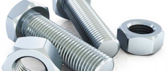
So, you have a bolt or nut with unknown thread parameters, and there is no measuring tool at hand other than a ruler. Let us immediately warn you that using a ruler can only get a rough result, so if you are going to regularly take such measurements, it is better to purchase a thread gauge or caliper.
Thread pitch - distance between turns
Threads are made according to approved standards, which made it possible to unify all threaded connections. The pitch of a metric thread is the distance between adjacent peaks or valleys of a threaded profile. It is this distance that we have to measure.
Measuring the internal diameter of a thread
The internal diameter of the cutting is controlled by a measuring device with pointed legs - calipers.
To organize computational work, you need to install the tool on a template part using a threaded gauge, and then make a comparison with the original internal diameter of the threaded connections. The caliper must be at an angle relative to the axis being measured. Also, measuring internal threads can be carried out with instruments for cylindrical threads. This is because the inside diameter has a smooth surface, which is ideal for the shape of the tips used in these instruments. Verification of the obtained measurements is done using plug gauges.
Measurement methods
There are quite a large number of different ways to determine the thread pitch. All of them are characterized by their own specific features that need to be taken into account. Common methods include:
- Using a regular ruler.
- The use of a special tool that can be used to determine the value in question. A thread pitch meter can be purchased at a specialty store.
- A caliper is a precision instrument. It is used quite often due to its high accuracy and versatility in use.
All of the above methods allow you to obtain fairly accurate data. The easiest way to take measurements is to use a thread-finding tool, but you can get by with a regular caliper.
Concept of thread pitch
Threads are used to connect a wide variety of products. To determine the bolt thread, you need to consider the distance between the same sides of the profile. The features of this concept include the following points:
- To determine the main parameters, a measurement is required.
- An inaccurate result can be determined by using a ruler.
- To increase the accuracy of measurements, you need to analyze several threads. That is why, depending on the length of the threaded surface, an analysis of 10 to 20 turns is carried out.
- It is recommended to take measurements in millimeters. In some cases the number is converted to inches.
The distance between the depressions can be measured using a special tool. The thread gauge is represented by a combination of special steel plates that have special cutouts. Various values are applied to the surface.
How to measure a nut
Most nuts have metric threads. Measuring the thread diameter will require a little more steps than in other cases. If possible, it is recommended to check the size of the bolt or screw used for it rather than the nut itself. This way you can achieve a more accurate result.
The value obtained after measuring the internal thread is an indicator of the internal diameter din.
In order to accurately determine the diameter of the metric thread of the hardware, you will need to find out the correspondence between din and the outer diameter of the bolt used. This is done using a special table.
Accuracy is controlled through the use of certain pass-fail gauges. One part should connect well with the nut, the second part, on the contrary, should not.
The nuts differ in appearance, and it is easy to determine upon detailed inspection. To find out the standard of the fastener, you may need to measure the height of the hardware, since there are high, low, extra high and other options.
Turnkey dimensions are also used to classify hex nuts. This is explained by the fact that hardware also differs in its types.
To accurately measure the thread pitch, it is possible to use the method considered in the case of a bolt. You will need a thread gauge or you will have to count the number of turns at the required interval.
Determining the dimensions of inch nuts
To check the thread dimensions of an inch nut, you need to examine the threads of the bolt or other hardware used with it. If you don’t have a suitable one at hand, but have information about the presence of an inch thread, then use the appropriate thread gauge. Do not forget to divide the resulting value by 25.4 mm.
Determining washer dimensions
For washers, a short designation in the form D is used, which stands for the diameter of the metric thread of the hardware used for the fastener.
To accurately measure indicators, a ruler or caliper is suitable. The result is a value that is slightly higher than the figure in the notation. This is explained by the fact that free movement is required during installation, which requires a small gap.
So, you have a bolt or nut with unknown thread parameters, and there is no measuring tool at hand other than a ruler. Let us immediately warn you that using a ruler can only get a rough result, so if you are going to regularly take such measurements, it is better to purchase a thread gauge or caliper.
Slicing technologies
Cylindrical pipe threads, which are of the inch type (both internal and external), can be cut manually or mechanically.
Manual thread cutting
Cutting a thread using a hand tool, which uses a tap (for internal) or a die (for external), is performed in several steps.
- The pipe being processed is clamped in a vice, and the tool used is fixed in a driver (tap) or in a die holder (die).
- The die is put on the end of the pipe, and the tap is inserted into the inside of the latter.
- The tool used is screwed into the pipe or screwed onto its end by rotating a driver or die holder.
- To make the result cleaner and more precise, you can repeat the cutting procedure several times.
Cutting threads on a lathe Mechanically, pipe threads are cut according to the following algorithm:
- The pipe being processed is clamped in the machine chuck, on the support of which a thread-cutting tool is fixed.
- At the end of the pipe, using a cutter, a chamfer is removed, after which the speed of movement of the caliper is adjusted.
- After bringing the cutter to the surface of the pipe, the machine turns on the threaded feed.
It should be borne in mind that inch threads are cut mechanically using a lathe only on tubular products whose thickness and rigidity allow this to be done. Making pipe inch threads mechanically allows you to obtain a high-quality result, but the use of such technology requires the turner to have the appropriate qualifications and certain skills.
Measuring thread pitch without a thread gauge
Parts with external thread
Often the need to determine the thread pitch arises sporadically, at one time. And, of course, in such a situation there is no thread gauge at hand, and it makes no sense to buy one for one-time measurements. It will be useful to learn how to measure the thread pitch with a ruler or caliper. These measuring tools make it quite easy to determine the desired parameter.
The easiest way is to measure the threads of a bolt or other externally threaded part. When measuring a metric thread, it is recommended that you first attach the ruler to the threaded part and try to align the millimeter divisions of its scale with the tops of the ridges of the threaded profile. If they coincide, then the step is 1 mm. Otherwise, you will have to carry out slightly more complex measurements.
To determine the thread pitch, you need to count the number of turns on a section of a rod of a certain length, for example, 10 mm or 20 mm. To obtain a more accurate result, it is recommended to take measurements on a 20 mm area. The required length is measured by applying a ruler to the bolt shaft, or using a caliper. It would be more accurate to measure the bolt thread pitch with a caliper. In the measured area, count the number of turns. After this, the length of the section must be divided by the resulting number of turns minus one turn. As a result, we obtain the value of the thread pitch.
When determining the pitch of an inch cutting, it is necessary to measure the length of the rod equal to one inch (25.4 mm). For accurate measurements, it is better to use a ruler or caliper with an inch scale. The number of turns in this area will be the thread pitch. If the length of the threaded section is less than one inch, then you need to determine the number of turns in a section of half an inch (12.7 mm), and then multiply the result by 2.
Internally threaded parts
There are two ways to measure the thread of a nut or other internally threaded part without a thread gauge. The first method involves selecting an exactly suitable counter bolt and then measuring its thread pitch. If you can’t find the counter bolt, then you need to use a strip of paper (this is method No. 2).
It should be pressed against the thread so that an imprint of the profile remains on the paper. You can improve the visibility of marks by tracing the edges with a marker. After this, on paper you need to mark the distance between the extreme marks with a ruler and count the number of turns. Then the resulting distance is divided by the number of turns minus one turn. Instead of measuring paper using this method, you can use a pencil, match or other soft wood product of a suitable size, which is pressed against the thread.
Rules for using vernier calipers
In order for a measuring instrument to serve faithfully for many years, it is necessary to follow simple rules for its operation and storage. First of all, mechanical damage that may occur as a result of a fall or force should be avoided. In addition, during the process of measuring parts, the jaws of the caliper must not be allowed to skew. To prevent this from happening, they must be fixed in a certain position on the part being measured using a locking screw.
The device should only be stored in a soft case or hard case. The second option is preferable, as it can provide protection from accidental deformations. The place for storing the caliper must be chosen in such a way that sawdust from various materials, dust, water, chemical mixtures, etc. do not get there. Plus, the threat of heavy objects falling onto the tool must be eliminated.
After each use of the caliper, it must be thoroughly wiped with a clean, soft cloth.
Naturally, we should not forget about observing safety rules when operating this device. At first glance, it does not pose any threat to health, but this is not entirely true. The fact is that the ends of the jaws for measuring internal dimensions are quite sharp, so you can easily get hurt if handled carelessly. Otherwise, the tool is completely safe.
When performing any carpentry or plumbing work, you need to know how to measure with a caliper, as well as be able to use it. This common universal metric tool is used to take internal and external linear dimensions from a part. The caliper allows you to measure diameters (internal and external) and the depth of the hole.
Accuracy classes and marking rules
A thread belonging to the inch type, as indicated by GOST, can correspond to one of three accuracy classes - 1, 2 and 3. Next to the number indicating the accuracy class, put the letters “A” (external) or “B” (internal). The full designations of thread accuracy classes, depending on its type, look like 1A, 2A and 3A (for external) and 1B, 2B and 3B (for internal). It should be borne in mind that class 1 corresponds to the coarsest threads, and class 3 corresponds to the most precise threads, the dimensions of which are subject to very stringent requirements.
Maximum size deviations according to GOST
To understand what parameters a specific threaded element corresponds to, it is enough to understand the designation of the thread that is applied to it. The designation in question is used by many foreign manufacturers who work according to American standards relating to elements of threaded connections.
An example of a symbol for an inch thread
This marking contains the following information about the thread:
- nominal size (outer diameter) – first digits;
- number of turns per inch of length;
- group;
- accuracy class.
Safety rules when working with the device
Despite the simplicity of the tool, there are certain rules for its operation that must be strictly followed. The main provisions are as follows:
- The cleanliness of the device must be excellent, regardless of whether it is metric or inch. This will help extend its service life and avoid possible failure.
- To store the device, you need to get a strong and dense container with a hard surface. The ideal option would be a box or container.
- You cannot use other devices that are not intended for carrying out measuring manipulations instead.
- The workpiece with the markings made must be firmly fixed and in a stationary position. If this is not done, a significant measurement error may occur.
- The master, regardless of experience and skills, must wear special clothing to avoid the possibility of injury.
- It is strictly forbidden to operate a faulty product. The probes should be smooth, no scratches, chips or dents. The presence of defects will negatively affect the accuracy of the measured data and subsequent calculations.
It is worth noting that many problems arise due to the poor quality of the materials used in the manufacture of products. Long service life is guaranteed for steel structures. If you purchased an inexpensive product with a body made of plastic, expect it to fail prematurely. Plastic is not particularly durable, so with regular active use of the device, it can quickly fail.
Accuracy classes and marking rules
A thread belonging to the inch type, as indicated by GOST, can correspond to one of three accuracy classes - 1, 2 and 3. Next to the number indicating the accuracy class, put the letters “A” (external) or “B” (internal). The full designations of thread accuracy classes, depending on its type, look like 1A, 2A and 3A (for external) and 1B, 2B and 3B (for internal). It should be borne in mind that class 1 corresponds to the coarsest threads, and class 3 corresponds to the most precise threads, the dimensions of which are subject to very stringent requirements.
Maximum size deviations according to GOST
To understand what parameters a specific threaded element corresponds to, it is enough to understand the designation of the thread that is applied to it. The designation in question is used by many foreign manufacturers who work according to American standards relating to elements of threaded connections.
An example of a symbol for an inch thread
This marking contains the following information about the thread:
- nominal size (outer diameter) – first digits;
- number of turns per inch of length;
- group;
- accuracy class.
If you have a question, how to determine the type and size of thread Connecting fittings for pipes and hoses
connections use the table below.
Please note the following:
- connections with inch threads are highlighted in color
- next to the inch step size in tpi the step size in mm is indicated
- connections with external tapered threads usually do not have a threaded groove
- BSPT and NPT conical fittings are very similar, but BSPT has a mark on the hexagon
An important note - situations are quite possible when the inch and metric pitches are very close in size (this is possible on JIC connections).
Read also: Scraper conveyor operating principle
In this case, it is possible to confuse the inch thread. American cylindrical inch thread UNF (Unified Thread Standard)
UNC UNF and metric threads.
Threaded fasteners are one of the most popular for attaching parts, assembling products, equipment, and structures. There is no industry where it is not used. There are many thread characteristics: pitch, tolerance range, number of starts, nominal diameter, profile type and others. One of these is units of measurement, inches or millimeters.
There is often a situation when it is necessary to replace a bolt, pin or screw, but the fastener purchased for maximum similarity “by eye” is not screwed into the mounting hole. One of the reasons is an attempt to screw a fastener with an external inch thread into a hole with a metric thread. Or vice versa. This situation often arises when replacing fasteners on products or equipment manufactured in the UK, USA, Japan, or Australia. There, inch threads have priority.
How to distinguish an inch thread from a metric thread? There are two main ways - by measuring the pitch and diameter or using a special tool.
Measurement
Fastener thread markings are done differently in metric and inch systems. In metric, this is an indication of the thread pitch (the distance between adjacent threads) in millimeters, while in inch it is the number of threads per inch.
Determining the type and size of fastener thread comes down to the following operations. Use a caliper to measure the diameter. Then, using an inch ruler or caliper, measure the number of threads in one inch and the thread pitch. You can also use a regular ruler with measured 2.54 mm (1 inch = 2.54 mm). The metric thread pitch on small fasteners can be found by measuring the distance between 10 turns and dividing the resulting value by 10. The resulting values should be compared with the table below. The maximum match in diameter, number of turns, pitch indicates the size and type of thread. It should be noted that there are many different types of inch threads. The table shows the most common ones in the diameter range from 8 mm to 64 mm.
You can also use a thread gauge to measure threads. This is its direct purpose. A thread gauge is a set of plates with protruding teeth for a specific thread, united on a single axis. The thread size is engraved or permanently inked on the plate itself. Checking the thread is done by applying plates that are closest in size to the thread. If there is a complete match, without gaps, the thread can be considered defined, and its size can be viewed on the thread gauge plate. Thread gauges are produced separately for metric, inch threads or both types.
Comparative characteristics
First of all, when choosing a caliper, you will need to decide on its dimensions and the parts that will be measured.
For small surfaces not exceeding 13 cm, it is recommended to use a tool up to 150 mm. This is the most common model, it is convenient and easy to use and store. For parts 20–30 cm in size, it is better to use a larger caliper, but the control is quite complicated, especially if the part is on the machine. When determining the size of a tool, its accuracy and measuring step are also important. When turning, it is necessary to select equipment of increased accuracy, class 0.01 mm, with possible errors of up to 0.02 mm.
For working with wood, lower precision is suitable, since the raw material is soft and can expand from moisture. For carpentry work, models will be cheaper, and their choice is much wider.
Additional functions are an important part of electronic calipers. Modern models help measure in mm and inches, but fractional data does not show everything. Other functions include:
- ability to connect to a computer - models of this type will help simplify the calculations of a large number of parts when you need to draw up a specific measurement report. The connection can be wired or wireless; after synchronization, a report is created in electronic form,
- Automatically turning off or turning on the device allows you to increase battery life.
The last factor that is taken into account when choosing is the material of the product. The service life and protective characteristics depend on this parameter. It is recommended to buy a stainless steel caliper, which does not corrode and is not afraid of stress. For turning work, it is better to take equipment that is protected from oil. Outdoor work requires models with protection from dust, moisture, class IP54 and higher.
Metric thread. Profile.
Metric thread profile according to GOST 9150 (ST SEV 180)
The nominal thread profile and the dimensions of its elements must correspond to those indicated in the figure and table.
d is the outer diameter of the external thread (bolt); D—outer diameter of the internal thread (nut); d2 is the average diameter of the bolt; D2 - average diameter of the nut; d1 - internal diameter of the bolt; D1 - internal diameter of the nut; P - thread pitch; H is the height of the original triangle; R is the nominal radius of curvature of the bolt root; H1 - working height of the profile.
Notes:
- The shape of the bolt thread root is not regulated and can be either rounded or flat-cut. A rounded cavity shape is preferred.
- The shape of the nut thread root is not regulated.
The table shows the dimensions of the thread profile elements. The shape of the screw thread cavities is not regulated by the standard; rounding of the depressions (with radius R) reduces stress concentration and increases the strength of the screw under cyclic loading.
According to GOST 24705 (ST SEV 182), the thread is metric, the main values of thread diameters are determined by the formulas:
where d3 is the internal diameter of the bolt.
Main settings
Each thread has precise geometric parameters.
Metric is characterized by a triangular thread profile, which is also called fastening. It is used for parts connected to each other by screwing. The profile size is determined by its height. The profile height (H) is the segment from the base to the top of an equilateral triangle, which is formed by a transverse section of the coil. The protrusions and depressions are made in the form of triangles with cut off vertices. In some cases, the depressions are rounded.
If the sides of each turn are mentally extended to the point of their intersection, then they will form a profile angle (α).
Thread profile
The main parameters indicated in the designation of a metric thread characterize its size. These include diameter and pitch. Metric thread designations indicate the main parameters.
Thread diameter is divided into 4 types:
- outer;
- interior;
- average;
- nominal.
Thread parameters such as stroke (Ph) and pitch (P) are interdependent and equal for a single-start system.
Thread stroke and pitch
The section separating the points of the same name on two turns is the thread pitch. There are main steps (large) and small steps.
Thread lead is a segment connecting two identical points on adjacent turns of the same thread. In the case where there are several entries, the move is expressed through the product of the number of steps and the number of entries.
The main thread elements also include:
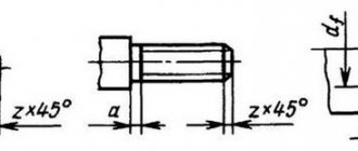
- A surface inclined 45º in front of the inner or behind the outer is called a chamfer. It plays a role in connecting elements.
- Run-off is the place of transition to the uncut surface of the part. These two indicators are united by length, that is, a segment with turns, chamfer and runoff.
For metric threads, the main dimensions are summarized in tables of the relevant standards: GOST 9150-2002, GOST 8724-2002, GOST 24705-2004.
Possible structural deviations caused by the properties of materials are reported by tolerance fields, with values not exceeding the nominal profile formed by the maximum of the material. These indicators affect the accuracy of the thread fit - the density of penetration of the protrusions into the gaps.
Thread tolerance fields are divided into three accuracy classes. And also 4 types according to your preference.
Connecting thin-walled parts
If it is necessary to connect thin-walled parts, then it will not be possible to directly use a threaded connection: the number of turns may be too small to reliably hold the fastener within the thickness of the part. In such cases, a flange connection is used. In this case, the edge of the part adjacent to the joint is strengthened by special stamping or welding of a flange - a thickening in which holes are made and threads are cut. If the configuration of the product allows, then sometimes instead of a full flange, only nuts are welded at the fastening points.
Flange connection
If the parts to be connected are cylinders of the same diameter and thickness, there is another method: an internal thread is cut on one cylindrical surface, and an external thread of the same nominal diameter is cut on the other. Next, the parts are screwed onto each other. This connection method does not require the application of large forces to the fastening point and is used for lightly loaded structures, such as, for example, cylindrical instrument casings.
Measurements of the dimensions of the pattern on the protectors
How to measure tire tread if you need to assess the degree of wear? A depth gauge will help, which takes measurements along the entire tire tread. It should be taken into account that wear is almost always uneven, and the number of measurements should be at least 3...5, and on evenly distributed areas of the tire tread for assessment. Before measurements, the tire should be thoroughly cleaned of dirt, dust and fragments of small stones stuck inside.
Sometimes you need to solve the problem of how to measure the tire tread with a caliper to determine the degree of uniformity of wear. This establishes the wear of the tread tires not only in depth, but also along the radius of transition from the circle of protrusions to the circle of depressions. They do this. The depth of the pattern on the new tire tread is measured, and then the linear size of the visually changed zone on the used part. The difference will determine the degree of wear and help you make the right decision about replacing the wheel.
All measurements are made with a depth gauge, which must be installed strictly perpendicular to the tire tread.
Measuring tread wear with a Columbian
Metric thread
The main difference between a thread of this type and similar ones is that only in a metric thread the profile angle is 60° (there are also threads with an angle of 55° and 47°).
Metric threads are used everywhere, including in metric fasteners. Due to its widespread use, it was necessary to create an impressive number of varieties in order to adapt this universal thread to different situations.
Rectangular thread
Table 3 presents data on rectangular threads.
Rectangular threads are most often made with a square tooth profile. But some manufacturers use rectangular profiles with an extended flange of the horizontal part for reinforcement
Table 3: Thread dimensions and helix pitch
| Nominal thread diameter d, mm | Step P | |||||
| 1 row (preferred) | Row 2 (permissible) | large | small 1 | small 2 | small 3 | small 4 |
| 8 | 2,00 | 1,50 | 1,25 | |||
| 9 | 2,00 | 1,50 | ||||
| 10 | 2,00 | 1,50 | 1,25 | |||
| 11 | 3,00 | 2,00 | 1,25 | 1,00 | ||
| 12 | 3,00 | 2,00 | 1,50 | |||
| 14 | 3,00 | 2,00 | ||||
| 16 | 4,00 | 2,00 | 1,50 | 1,00 | 0,75 | |
| 18 | 4,00 | 2,00 | ||||
| 20 | 4,00 | 3,00 | 2,00 | |||
| 22 | 8,00 | 5,00 | 4,00 | 3,00 | 2,00 | |
| 24 | 8,00 | 5,00 | 4,00 | 3,00 | 2,00 | |
| 26 | 8,00 | 5,00 | 4,00 | 3,00 | 2,00 | |
| 28 | 8,00 | 5,00 | 4,00 | 3,00 | 2,00 | |
| 30 | 10,00 | 6,00 | 3,00 | |||
| 32 | 10,00 | 6,00 | 3,00 | 2,00 | ||
| 34 | 10,00 | 6,00 | 3,00 | |||
| 36 | 10,00 | 6,00 | 3,00 | 2,00 | 1,50 | |
| 38 | 10 | 7 | 6,00 | 5,00 | 3,00 | |
| 40 | 10 | 7 | 6,00 | 5,00 | 3,00 | |
| 42 | 10 | 7 | 6,00 | 5,00 |
Geometric parameters
Let's consider the geometric parameters that characterize the main elements of metric threads.
The nominal thread diameter is designated by the letters D and d. In this case, the letter D refers to the nominal diameter of the external thread, and the letter d refers to a similar parameter of the internal thread. The average diameter of the thread, depending on its external or internal location, is designated by the letters D2 and d2. The internal diameter of the thread, depending on its external or internal location, is designated D1 and d1. The inside diameter of the bolt is used to calculate the stresses created in the structure of such a fastener. The thread pitch characterizes the distance between the crests or valleys of adjacent threaded turns. For a threaded element of the same diameter, a basic pitch is distinguished, as well as a thread pitch with reduced geometric parameters
The letter P is used to denote this important characteristic. The thread lead is the distance between the crests or valleys of adjacent turns formed by the same helical surface. The progress of the thread, which is created by one screw surface (single-start), is equal to its pitch
In addition, the value to which the thread stroke corresponds characterizes the amount of linear movement of the threaded element performed by it per revolution. A parameter such as the height of the triangle that forms the profile of the threaded elements is designated by the letter H.
Metric thread diameters (mm)
Complete table of metric threads according to GOST 24705-2004
GOST 8724 This standard contains requirements for the parameters of the thread pitch and its diameter. GOST 8724, the current version of which came into force in 2004, is an analogue of the international standard ISO 261-98. The requirements of the latter apply to metric threads with a diameter of 1 to 300 mm. Compared to this document, GOST 8724 is valid for a wider range of diameters (0.25–600 mm). At the moment, the current edition of GOST 8724 2002, which came into force in 2004 instead of GOST 8724 81. It should be borne in mind that GOST 8724 regulates certain parameters of metric threads, the requirements for which are also specified by other thread standards. The convenience of using GOST 8724 2002 (as well as other similar documents) is that all the information in it is contained in tables, which include metric threads with diameters within the above range. Both left-handed and right-handed metric threads must meet the requirements of this standard.
GOST 24705 2004
This standard stipulates what basic dimensions a metric thread should have. GOST 24705 2004 applies to all threads, the requirements for which are regulated by GOST 8724 2002, as well as GOST 9150 2002.
GOST 9150
This is a regulatory document that specifies the requirements for the metric thread profile. GOST 9150, in particular, contains data on what geometric parameters the main threaded profile of various standard sizes must correspond to. The requirements of GOST 9150, developed in 2002, as well as the two previous standards, apply to metric threads, the turns of which rise from the left upward (right-handed type), and to those whose helical line rises to the left (left-handed type). The provisions of this regulatory document closely echo the requirements given by GOST 16093 (as well as GOSTs 24705 and 8724).
GOST 16093
This standard specifies the tolerance requirements for metric threads. In addition, GOST 16093 prescribes how metric type threads should be designated. GOST 16093 in its latest edition, which came into force in 2005, includes the provisions of the international standards ISO 965-1 and ISO 965-3. Both left-hand and right-hand threads fall under the requirements of such a regulatory document as GOST 16093.