Threaded connections are very widely used in mechanical engineering, so the tool for making threads is one of the most common.
Threads are distinguished:
- according to the location of the turns - external and internal;
- in the direction of the helix - right and left;
- according to the profile shape of the grooves - triangular, trapezoidal, rectangular, thrust and special;
- in the direction of the generatrix - cylindrical and conical;
- according to the size system - metric and inch.
Depending on the size of the thread, the type of production and the design of the parts, different types of thread-cutting tools are used:
- thread cutters (rod and shaped single-thread and multi-thread);
- taps (hand, machine, nut, machine, tool, master, etc.);
- round dies;
- threading heads;
- thread cutters.
Thread cutting tool
An axial multi-edged tool for forming and processing internal threads is called a tap, and external threads are called a die.
Hand taps are used for cutting internal threads.
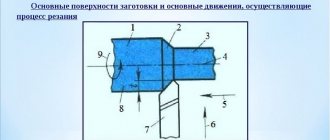
The working part of the tap with length f is divided into cutting (taking) and guiding (calibrating) parts with lengths l1 and l2, respectively (Fig. 1, a). The cutters of the cutting part have main edges located on the conical surface and auxiliary edges that are part of the threaded profile (Fig. 1, b). The guide part serves to guide the tap and self-feed by screwing in, and also serves as a reserve for regrinding. The cone angle of the cutting part depends on the angle φ, which is set equal to 5° for hand taps, 3°30′ for nut taps and 6°30′ for machine taps. The guide part has a reverse taper to reduce friction and eliminate dangerous jamming of the tap in the hole.
Rice. 1. Structural elements (a), thread profile (b) and geometric parameters (c) of the tap
The length of the tap portion of the tap is taken to be 45 S for a rough tap, 2.55 S for a medium tap, and (1.5–2.0) S for a finishing tap, where S is the pitch of the thread being cut. Machine taps are made with a short taper equal to (1.5–2) S.
The rake angles of the taps are selected depending on the material being processed according to the following data:
- for soft steel γ = 12–15°;
- steel of medium hardness γ = 8–10°;
- hard steel γ = 5°;
- cast iron and bronze γ = 0–5°;
- light alloys γ = 25–30° (Fig. 1, c).
The tail part of the tap is designed to secure it in a driver or chuck and to transmit torque.
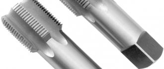
Hand taps are produced in sets. The kit includes three taps, which are divided according to their purpose into rough, medium and finishing. Chernovoy cuts the thread, removing up to 60% of the metal; the middle one gives more accurate threads, removing up to 30% of the metal; the third (finishing) tap performs final cutting and calibration of the thread, removing up to 10% of the metal.
For cutting pipe and small metric threads, use a set of two taps.
The taps included in the set differ from each other in thread profile and length of the intake part.
According to the design of the cutting part, two types of taps are distinguished - cylindrical and conical (Fig. 2; a, b).
Rice. 2. Formation of a cutting surface in a set of taps: a - cylindrical design, b - conical design
With a cylindrical tap design, all three tools in the set have different diameters. The finishing tap has a full thread profile. The diameter of the average tap is less than normal by 0.6 of the cutting depth, and the diameter of the rough tap is less than the thread diameter by the full cutting depth.
The length of the intake part, taking into account the distribution of thread cutting work between the three taps of the set, is set in the ratio 4:2:1. Thus, for a rough tap the length of the intake part is 6–7 threads, for a medium tap it is 3–3.5, and for a finishing tap it is 1.5–2 threads.
The cylindrical design of the tap ensures that the tips of the teeth cut chips in the form of wide platforms.
With a tapered tap design, all three tools in the set have the same diameter and full thread profile with varying tap lengths.
The thread within the intake part is made conical and additionally cut along the tops of the teeth into a cone.
For conical taps, the cutting part is equal: for a rough tap - the entire length of the working part, for a medium tap - half of this length, for a finishing tap - two threads.
Tapered taps are usually used when cutting through holes. Blind holes are cut with cylindrical taps.
The rear (back) surface (Fig. 1, c) of the cutting teeth is backed up in a spiral, which allows maintaining a constant profile of the teeth after they have been sharpened.
Collars and clamps . Threading with hand taps is carried out using cranks that fit onto the square ends of the shanks.
The most common are simple double-sided knobs (Fig. 3).
Rice. 3. Double-sided driver: a, a1, a2 - holes for tap shanks
Universal gates (Fig. 4) are a frame 1 with two crackers - movable 3 and fixed 4, forming a square hole. One of the handles 2 ends with a screw for clamping the square of the tap.
Rice. 4. Universal driver: a - hole for the tap shank
Another version of the universal driver is shown in Fig. 5. This driver allows you to work with taps whose square sizes range from 5x5 to 25x25 mm.
Rice. 5. Universal wrench
Round dies are used for cutting fastening threads on bolts, screws and studs when working manually and on machines (revolving, automatic, etc.).
The round die on each tooth 2 (Fig. 6, a) has a rear 1 and front 5 surface, a back of the tooth 3 and a cutting edge 6 formed by a chip hole 4. The round die has a cutting and guide part with lengths l1 and l2, respectively (Fig. 6 , b). The length of the cutting part is equal to one and a half threads of thread, and the thickness of the die is seven to eight threads.
Rice. 6. Structural elements (a), main parts (b) and shapes of chip holes (c) of a round die
Rake angles are taken for hard materials being processed γ = 10–12°; for materials of medium hardness γ = 15–20°; for soft materials γ = 22–50°.
Dies are used (Fig. 7) solid (a), split (b) and sliding.
Rice. 7. Dies
When cutting manually, round and sliding dies are installed in special cranks and clamps.
The collars for round dies are made of a frame into the hole of which the die is placed (Fig. 8).
Rice. 8. Driver for a round die
The die is kept from turning by three locking screws (1, 2 and 3), the conical ends of which fit into recesses on the side surface of the die. The fourth screw fits into the slot of the adjustable die and secures the correct thread size.
The clamps for sliding dies (Fig. 9, a) are an oblique frame with two handles. In the central hole of the frame with dimensions A and C, sliding dies are installed and centered. Installation of the sliding dies to the required size is carried out using a pressure screw 1 acting on the movable part of the sliding dies.
Clusters for cutting threads on pipes differ from conventional ones in that four steel combs 2 fit into the slots of the clamp holder (Fig. 9, b).
Rice. 9. Dies: a - for sliding dies; b - for cutting threads on pipes
By turning the upper handle 1, you can bring the dies closer together or move apart, and thanks to this, use the same die for cutting threads on pipes of different diameters. The pipe die is equipped with guides 3, which are adjusted in the same way as the dies, by a lower handle 4. This ensures the correct position of the die on the pipe when cutting threads.
Thread cutting order
Before cutting, it is necessary to chamfer the outer part of the pipe or workpiece at an angle of 45°. This is necessary to facilitate the first turns and fix the die.
Further actions:
- Secure the pipe or workpiece in a strictly vertical position. The best option to avoid distortions is a bench vise, but you can also use a gas wrench.
- Lubricate the tool with oil.
- Place the die on the head of the rod in a strictly horizontal position and start with the first few circles.
- If there is obvious misalignment in the first laps, remove the die, tap the workpiece and start again.
- When rotating on the first turns, simultaneously press evenly on the handles of the driver to begin the cutting process.
- After the first few turns, check that the thread is cut correctly. This can be done by checking the horizontality of the dies and the knob, which can be checked with a level. Next, with the correct position of the tool, you can continue cutting the pipe thread with a die to the entire required length.
- When approximately the middle of the length is reached, the pressing force can be weakened, then the self-tightening process begins.
- After one or two turns, it is necessary to turn the die half a turn back to remove chips.
- After cutting to the desired length, simply return the tool back along the finished thread.
It is necessary to take into account that the die can have several numbers, most often 2. In this case, after cutting the rough thread, it is necessary to go through each of the numbers in turn to finally form the thread profile.
Features of the structure of taps
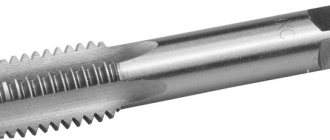
The tap, which belongs to the group of metalworking and turning cutting tools, has the shape of a rod on which the cutting element is made. It is intended for cutting internal threads, that is, inside holes in various materials, as well as for repairing damaged internal threads.
A set of metal-cutting tools: a - drills, b - countersinks, c - reamers, d - taps, e - dies.
The tools consist of a working and a tail part. In turn, the working part is divided into an intake (cutting) and calibrating section. The cutting section is responsible for the main function of the tap - cutting threads, and, most often, has a conical shape. It has teeth in the form of incisors placed around a circle. The calibrating section performs the task of final formation. It is made in the form of a cylinder with teeth that are a continuation of the teeth of the cutting section. This section is much longer than the fence. The working part is cut in the longitudinal direction with grooves, which are designed to form cutters and remove chips. Taps with a diameter of up to 22 mm have three grooves. Special purpose devices can be manufactured without grooves. The grooves can be straight or helical.
The tail part has the shape of a cylinder. At the end of the section there is a square for installation in the fastening tool. In this part, the diameter marking is stamped out. Using a shank, the tool is fixed in a hand holder or machine chuck.
How to properly cut threads with dies and taps - instructions
Often, when performing home repairs, it becomes necessary to make threads - external or internal. In order not to involve specialists in this, but to do it yourself, you need to purchase a special tool. Cutting with dies and taps does not require any special skills or abilities. It is enough to know their types and technical parameters.
A little about the features of the tool
The first step is to decide on the type of thread. It is divided into 2 main types: metric and inch. The first one with the left direction is most often used. In order not to measure the distance between the grooves, you can find out the type by the shape. A metric thread in cross-section is an equilateral triangle, and an inch thread is an isosceles one.
Which products use a certain type of thread? Fasteners use metric, while water pipes use inch. In addition, you need to take into account the following factors that influence the process of cutting connecting elements.
- If the thread is intended to be connected to a finished part, its geometric dimensions must be appropriate.
- When manufacturing complete fasteners, it is recommended to use the metric type.
- The diameter of the workpiece must be different from the thread size. For the outside - to a lesser extent, for the inside - to a greater extent.
Self-cutting of threaded connections is carried out using dies and taps. They are made of high-strength steel with a standardized working fluid size.
Outdoor
The die is a nut with internal slots and external clamps for turning the tool. It can be of various shapes - round, square or hexagonal. If the work is carried out at home, you will need a vice to fix the part.
Die holder and dies
Before performing work, the main thing is to choose the correct diameter of the workpiece. It should be 0.2-0.3 mm smaller than the size of the future thread. For metric, you can use the data from the table.
The workpiece should be prepared in advance. If its cross-section is not a circle, you need to turn it. Then a conical chamfer is removed from the end part to mark the first turn of the thread.
Next you need to follow the instructions exactly:
- Having secured the workpiece in a vice, the correctness of its location is checked.
- Installing the die into the die holder. Its surface must be in the same plane as the surface of the workpiece end.
- The first turn is performed with little effort. It is important to make turns in the right direction.
- Having reached the lower limit, the die must be turned in the opposite direction.
External thread cutting
One such pass will not be enough to form a thread with good geometry. It is recommended to repeat the procedure 3-4 times until the die is freely screwed onto the workpiece. To check the quality, tighten a nut of the appropriate diameter. If force is observed, you can treat the outer part of the workpiece with fine-grained sandpaper.
Internal
Taps must be used to form internal threads. They are a cylinder with an external notch. If you need to process small parts with a diameter of up to 20 mm, you can use a manual type of tap. Larger sizes require machining using a machine.
Main settings
Tapping threads.
In general, cutting a thread means making a projection on the inside surface of a hole so that it forms a helix. Such a protrusion, like all threads, is characterized by the following basic parameters: the helix angle, pitch, type of protrusion profile and profile elevation angle, outer and inner diameter. In addition, it is customary to distinguish another depth, determined by the outer and inner diameters.
In direction, the thread can be right-handed, when the helical protrusion rises counterclockwise, and left-handed, when the direction of rise of the protrusion coincides with the clockwise movement. Based on the shape of the protrusion profile, there are two main types: threads with a rectangular profile and with a triangular profile. There are also special profile forms, but they are practically not used in everyday life.
The main thread is metric. This profile is a triangle with a profile angle of 60º. According to the pitch, metric is divided into threads with a large pitch and with a fine pitch. An example of the full designation of a metric thread is M10x1-6N. The designation should be understood as follows:
Tap selection table for thread cutting.
- M – metric thread;
- 10 – nominal diameter;
- 1 – thread pitch;
- 6Н – tolerance limits for dimensional deviations.
With normal (large pitch) the designation is abbreviated (for example, M10). In the case of a left-hand thread, the designation LH is entered.
The second most common type in everyday life is the cylindrical pipe type. The profile is a triangle with an apex angle of 55º. This type is used when connecting pipes and cylinders, where increased tightness of the connection is required. Straight pipe threads are designated by the letter G, indicating the diameter in inches.
The thrust thread is based on a trapezoidal profile with inclination angles of 3º on one side and 30º on the other. The designation includes the letter S, diameter and pitch.
Preparing for slicing
Cutting internal threads begins with drilling the desired hole - through or blind. The main condition: the hole must be smaller than the thread diameter. When drilling a hole, it is recommended to select a drill from the following condition:
Classification of types of carving.
- for M3 thread – drill diameter 2.5 mm;
- at M4 – 3.4 mm;
- at M5 – 4.2 mm;
- at M6 – 5 mm;
- at M8 – 6.7 mm;
- at M10 – 8.4 mm.
If it is necessary to cut a large thread, the hole diameter is determined by approximately multiplying the thread diameter by 0.8.
The hole for cutting internal threads is made on a drilling machine or electric drill. In the latter case, the workpiece is clamped in a vice. It is necessary to ensure that the drill is directed strictly vertically. The top edge of the hole is chamfered to facilitate entry of the tap. It can be done with a larger diameter drill or file. After drilling, the hole is thoroughly cleaned of chips, which is especially important for blind holes.
Choosing the right tap
Scheme of cutting external and internal threads.
First, the type of tap is selected based on the type of thread and its purpose (profile shape, thread pitch, tolerances). According to the accuracy requirements (class), it is determined whether a single tap should be used or a set is required. In addition, taps are produced with different finishes of their cutting element, which affects the accuracy of cutting the thread profile.
The material in which the thread must be cut influences the choice of tap. Thus, the rake angle of the teeth must be taken into account. It is for steel – 5-10º, for copper alloys – 0-5º, for aluminum and alloys – 25-30º. Devices can be made from ordinary steels, high-strength steels or high-strength brazed steels, which must be taken into account when considering what strength of material is being processed.
The main choice is made based on the diameter of the hole in which the internal thread is cut. The diameter of the tap should be slightly smaller than the diameter of the hole. So, for a metric M20 thread (tap diameter 20 mm), the hole diameter is 19 mm. For metric threads, if there are no special requirements, then a standard pitch is performed. For example, M4 thread – pitch 0.7 mm; M5 – 0.8 mm; M10 – 1.5 mm; M12 – 1.75 mm, etc.