In this article we will try to understand what oil pipes are, which pipes are used at different stages of oil production and refining, and by what standards they are manufactured.
This is how many people imagine the scope of their application
And this is how she often looks in reality
Pipes that can be called oil pipes include two large categories of very, very different products:
- Oil field pipes;
- Pipes for oil transportation.
The first category, in turn, includes several more subspecies; Each of them has its own standards.
This:
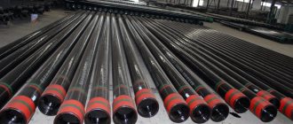
- Casing;
- Drilling;
- Pump and compressor.
Let's start with commercial ones.
Oil pipes for pumping oil and petroleum products
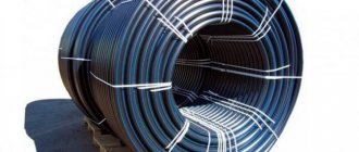
Fiberglass pipelines produced by SAFIT are designed for transporting multiphase oil and produced water, as well as corrosive media containing hydrogen sulfide, carbon dioxide, oxygen, acids, alkalis, and mechanical impurities.
SAFIT pipes are widely used in the oil and gas industry, when working in conditions of moving soils, flowing swamps and low average annual temperatures. Since 1996, fiberglass pipes have been used at more than 200 oil production wells and oil gathering sites of LUKOIL Western Siberia, Surgutneftegaz, Tatneft, Komineft.
increases the service life of pipelines by 5-8 times, eliminates the use of anti-corrosion protective agents, reduces the weight of the pipeline by 4-8 times, and eliminates the use of welding. The pipes are made by winding glass roving, pre-impregnated with an epoxy binder, followed by heat treatment.
Pipeline systems are designed for transporting hydrocarbons, including crude oil, diesel fuel, condensate, and reagents. The service life of oil pipes is greatly influenced by the natural and physical and chemical conditions in which the pipes operate: elevated temperatures of liquids, high flow rates, the presence of corrosive environments: hydrogen sulfide (H2S), carbon dioxide (CO2), chlorides (NaCl), salts and alkalis used in well treatment.
Pipe design
Butt joint
Joint assembly
Innovative technologies
- A special sealing layer with a specific elongation of up to 500%.
- A unique powerful bandage provides special protection against caisson and abrasive influences from the working environment.
- The socket-nipple key connection is reinforced by two rings connected to the plastic using a mechanical piercing method, ensuring equal strength of the connection nodes and the pipe wall.
Presentation Questionnaire
Unique advantages
- Service life more than 30 years.
- Operating temperature range from -50 to +50 °C. Low thermal conductivity coefficient.
- Simplicity and high speed of multiple installation and dismantling operations. Does not require welding.
- Low weight of the structure with high strength characteristics to bending, torsional and impact loads.
- Resistance to aggressive media - formation waters, alkalis, acids, gas condensate. Does not become overgrown with salts and other deposits.
- Water resistance is 30% lower than that of metal pipes.
- They do not require the use of electrical or chemical protection. They do not require insulation and associated costs.
What is required for certification?
This allows the buyer to include special requirements according to the design and service conditions.
This also allows the product to be manufactured according to the customer's order.
Note that the requirement in the specification must satisfy the need.
Typically, oil and gas utilities create their own FEED specifications, which are front-end engineering and development, or sometimes use available specifications from well-established companies such as Shell, Bechtel, EIL and Chevron.
Pipes are manufactured in accordance with GOST R 56277-2014
This standard applies to polymer composite pipes and fittings intended for underground and above-ground in-field pipelines of the oil and gas industry transporting oil, including high-water cut oil, oil and gas mixtures and emulsions, oil products, waste waters, associated petroleum gas, gas condensate and other corrosive substances. environments containing hydrogen sulfide, carbon dioxide, sulfur, salts, free oxygen, mechanical impurities, operated at operating pressures up to 4 MPa and operating temperatures from minus 65 to plus 90 °C.
Transportation
Layout along the route
Installation of seals
Assembly
Finished pipeline
Finished pipeline
We offer oilfield composite glass-basalt plastic pipes TU2296-009-71653326-2007, connecting and shaped parts intended for pipeline systems of the oil and gas industry transporting reservoir oil, incl. highly water-cut, oil-gas-water mixtures and emulsions, petroleum products, field wastewater, associated petroleum gas, gas condensate and other corrosive media containing hydrogen sulfide, carbon dioxide, sulfur, salts, free oxygen, mechanical impurities, etc. in the “UHL” climatic version 2 according to GOST 15150, for example, for operation in the macroclimatic regions of Western and Eastern Siberia, the Komi Republic, the Far East, the Ural-Volga region, etc.
The pipes are equipped with quick-installed connection units. Pipes and joints are designed for a working pressure of 40 kgf/cm2, while the strength and tightness margin of pipes and joints is at least 4, i.e. depressurization pressure of at least 160 kgf/cm2. All pipes and joints undergo appropriate tests during manufacture. The pipes have passed special tests for cyclic exposure to internal pressure at pressure differences from 0 to 80 kgf/cm2, as well as cyclic alternating bending loads.
How to choose a casing pipe for a well
The most important parameter of the well - its productivity - will depend on how correctly the diameter of the casing pipes is chosen. Guided by the desire to get a larger water flow, many try to select a casing pipe for a water well of the maximum diameter. This approach can only lead to the fact that well casing will result in serious financial costs.
You can avoid unnecessary costs for the purchase of casing pipes without losing the productivity of the well if you perform preliminary calculations and determine which pipe (with what diameter) will allow you to obtain water from the well in an amount sufficient for both watering green spaces and household purposes. Before proceeding with such calculations, it is necessary to determine the maximum water flow that will satisfy the owner of a dacha or country house.
Well using plastic casing
Let's look at the algorithm for determining this parameter. It has long been established that if the tap is opened completely, then about 0.7 cubic meters of water will flow out of it in an hour. In any country house, as a rule, water is spent for the following purposes:
- for the operation of plumbing equipment in the toilet;
- in kitchen plumbing equipment;
- to ensure the operation of the washing machine.
Water in country houses and dachas is also used for watering green spaces, which should also be taken into account. Taking into account all these factors, we can say with confidence that the maximum water flow will be about 3 cubic meters per hour. To ensure this flow rate, it is best to use a submersible pump with a casing diameter of 75 mm.
Now, in order to calculate what cross-section a metal or plastic pipe for a well should have so that such a pump can be installed in it, it is necessary to add a number of parameters to its diameter: the thickness of the pipe walls (for steel products - 6 mm), the gap that is required leave between the inner walls of the pipe and the pump housing. If in the calculations we take into account the size of such a gap, equal to 4 mm, then in the end we find that we need a pipe with a cross-sectional size of at least 87 mm. It is necessary to select a product with a standard cross-section (GOST 632-80 or another regulatory document will help with this), as close as possible to the value we calculated. In our case, this will be a casing pipe for wells, the cross-section of which is 89 mm.
Specifications
- Length - 8.6 m
- Working pressure – from 2 to 40 MPa
- Operating temperature – from minus 65°С to plus 90°С
- Medium - oil containing hydrogen sulfide, carbon dioxide, salts, free oxygen
- Modulus of elasticity in the annular direction – 17.6 MPa
- Modulus of elasticity in the axial direction – 9.1 MPa
Catalog Installation and operating instructions
What is a pipe class?
A piping grade or pipe class is a document that specifies the type of components such as pipe type, schedule, material, flange pressure ratings, branch types, valve types and valve trim material, gasket and all other specific requirements for components to be used for different liquids under different operating conditions at the plant.
The class of pipes is developed taking into account operating pressure, temperature and aggressive environment. The various material specifications are separated into a separate "piping class". The pipe grade is part of the piping specification.
A short number is used to cover all information applicable to a given pipe grade. This class of pipe is also included in the line number so that the structural engineer can easily determine the required material.
Assortment
| Options | Values | ||||||
| Pipe diameter, mm | 100 | 160 | 190 | 235 | 285 | 320 | 450 |
| Outer diameter (nipple), mm | 136 | 203 | 240 | 288 | 342 | 378 | 510 |
| Outer diameter (socket), mm | 165 | 240 | 280 | 340 | 400 | 440 | 580 |
| Weight 1 l.m. pipes no more than, kg | 7,2 | 13,3 | 16,5 | 24,1 | 31,0 | 40,5 | 59,0 |
| Bending radius, not less, m | 30 | 40 | 50 | 60 | 70 | 80 | 110 |
Pipe sizes
Pipe sizes are indicated in dimensions and nomenclature. Three different terms are commonly used to define pipe size.
NPS - Nominal Pipe Size
NB - pipe internal diameter
DN - nominal diameter
Pipe sizes are specified in the following standards
ASME B36.10 - Welded and seamless welded steel pipes (carbon and alloy steel)
ASME B36.19 - Stainless steel pipes
What is small diameter pipe and large diameter pipe?
In the project you can find terms such as small and large pipe diameter.
Small diameter pipes
A pipe size up to 2″ is considered a small diameter pipe. However, some companies consider pipe up to 2.5″ to be small in diameter.
Large diameter pipe
A pipe size above 2″ is considered a large diameter pipe.
Pipe length
Pipe length is indicated in meters or feet. During manufacturing, pipes are not produced at the same length, and when constructing a process plant, pipes of varying lengths may be required. To solve this problem, the standard defines pipe lengths in single random and double random categories.
Single random pipes:
These pipes range in length from 4.8 to 6.7 m with 5% lengths ranging from 3.7 to 4.8 m.
Double random pipes:
These pipes have an average minimum length of 10.7 m and a minimum length of 4.8 m with 5% lengths ranging from 4.8 to 10.7 m.
Reference-list
| Company | Year | Application |
| HALLIBURTON | 2015 | Drillable pipe |
| LUKOIL Western Siberia | 2014 | Infield pipe |
| HALLIBURTON | 2010 | Core pipe |
| LUKOIL Western Siberia | 2005 | Infield pipe |
| Yuganskneftegaz | 2004 | Infield pipe |
| TATNEFT | 1996 | Tubing pipe |
| CHPP No. 27 | 1994 | Pumping table salt |
Well development from scratch
A person involved in the construction of wells with water flushing from A to Z must take into account that all known drilling methods have their advantages and disadvantages, which will be discussed below.
- Screw method.
This option is deservedly considered simple and budget-friendly. The vast majority of units used today are developed on the basis of auger equipment. In this case, an Archimedes Screw, rotated by hand or by an electric motor, removes the earth. A significant disadvantage of this method is that the depth of the well will not exceed 10 meters. Washing is not required for such work.
- Rotary method.
If the desired depth exceeds 10 meters, then the deepening is carried out using a rotor. In reality, the process looks like this:
- The core structure, which has already been discussed above (a hollow product with a rotor and a chisel inside), is immersed in the ground. A rotating rotor creates a channel of a given depth, while flushing is carried out in a direct (the solution enters through the pipes and exits outside the structure) or reverse (the solution is pumped outside the part and removed using a pump) method;
- Optimal opening of the aquifer is more easily achieved through the second type of flushing. At the same time, the result is guaranteed through the use of complex equipment, the use of which inevitably entails impressive costs. That is why, most often, at the expense of efficiency, direct flushing is used, the result is satisfactory, and costs are significantly reduced.
- Percussion-rope drilling.
Despite its own moral and technical obsolescence, as well as labor intensity, this option continues to be in great demand. This state of affairs is due to the high quality and impressive service life of the well. This method is implemented as follows: a projectile is repeatedly dropped onto the ground surface from a certain height, punching a hole. Most often, this process is automated using a winch.
The need to use the solution during the work does not arise, which should also be considered a positive feature of the method under consideration.
The uncontrolled method is relevant provided that the channel depth does not exceed 10 meters. As in the case of other methods described above, when constructing wells with RVA machines, it is necessary to use a drilling mixture, which helps remove waste from the well and form reliable supports (walls) of the channel. In addition, the composition in question significantly contributes to softening the soil, which in itself simplifies the work performed and reduces the load on equipment.
The technique under consideration is more often used on an industrial scale rather than for creating water-bearing canals on the sites of private houses, since the use of the system involves the delivery and installation of complex equipment, which is not always appropriate and quite inconvenient.
Video about the features of choosing pipes for drilling wells:
Tests
Impact with a 100 kg hammer
Pipe bending tests
Joint bending tests
Installation of casing bored piles
Installation and installation of a pile foundation is carried out directly on the construction site. In principle, the technology for installing such a structure with your own hands is quite simple: you need to lower a pipe into the well, carry out reinforcement and concrete it. In length, such structures can be up to thirty meters with a diameter of up to one and a half meters, although with improved technical support, the length can be doubled and the cross-section increased to 3.5 m. With such parameters, the bearing capacity of bored supports will be 500 tons.
In most cases, the structure is buried 5 - 12 m with a diameter of 25 - 40 cm. Do-it-yourself assembly of metal structures is carried out according to the following scheme:
- The well is filled with concrete mortar per meter;
- the solution is compacted;
- the casing is gradually raised to the level when the concrete drops by 35 - 40 cm;
- this process must be repeated until the rod is completely filled with the mortar mass.
Pile design
The walls of the leader hole for the casing pipe during drilling become rough and loose due to collapsed soil, so a gap is formed between the hole and the metal structure, which is compacted with a solution, and the concrete, in turn, seeps into the soil structure and makes it stronger . This technology has one drawback, and it is that you cannot control the density of the concrete pour inside a long shaft. This minus can lead to erosion by groundwater of areas of the mixture that have not set, if there are any, of course.
The well for the pipe foundation is reinforced only in the upper part, while the reinforcement cage is buried 1.5 - 2 m into fresh concrete. Along with the casing pipe, the dry method is also used, suitable for stable and dense soils that can withstand the load without destroying the walls. The frame is installed in the well with your own hands, and then the mortar mass is filled. If bored wells are sunk into weak, watery soils without casing, then their walls must be reinforced with clay coating, the density of which must be at least 1.2 g/m3.
Documentation
Patent
Patent
ISO9001 Certification
Certificate
Test program
Oil pipeline composition
The system for transporting oil and petroleum products consists of many components:
- Linear structures. This group includes shut-off valves, access roads and helipads, anti-corrosion structures, passages, etc.;
- Oil pumping station (or oil pumping station). These are structures located along the pipeline; they are equipped with an electric drive pump, which can have a speed of up to 12,000 m3/h. Each pumping station, in turn, has additional facilities - boiler houses, transformer substations, etc.;
- Thermal stations, which may have thermal insulation protection. They are used as part of oil pipelines for pumping viscous products.
Pipelines for maintaining reservoir pressure RPM
RPM pipes are pipes for maintaining reservoir pressure. In their design and range, they are similar to field pipes, only oil field pipes are designed for pumping out and transporting oil, and water or special solutions are pumped into the oil reservoir using RPM. The RPM system is a complex of technological equipment necessary for the preparation, transportation and injection of the working agent into the reservoir of an oil field in order to maintain reservoir pressure and achieve maximum oil recovery from the reservoir.
The system of equipment for maintaining reservoir pressure (RPM) generally consists of water intake sections, a water supply line (with a large-diameter pipeline and pumping stations of the first, second and, if required, third water lift), treatment facilities for preparing water for injection into the oil reservoir , cluster high-pressure pumping stations in the field area, distribution pipelines with water distribution combs, from which water goes to injection wells.
To maintain reservoir pressure, both natural (fresh or slightly mineralized) and waste (drainage) waters, consisting mainly of reservoir (≈85%), fresh (≈10%) and storm water (≈5%) . Natural and waste waters may contain impurities of organic and inorganic origin. Natural waters may contain various gases, mechanical impurities, iron hydroxide Fe(OH)2 and iron hydroxide Fe(OH)3, as well as microorganisms that, to one degree or another, affect the corrosion process in metal pipes. In addition, droplets of oil may be present in wastewater, as well as a large amount of salts, reaching up to 300 g/l.
Fiberglass pipelines are resistant to transporting aggressive liquids. Pipes are not subject to corrosion (the material of the pipes is inert to acids, salts, alkalis, hydrogen sulfide and oxygen-containing compounds) The small weight of the pipes ensures their high strength (on average, the weight of fiberglass products is 5 times less than the weight of the same metal products).
PPD pipes
Laying PPD pipes
Laying PPD pipes
What is a pipeline specification?
Pipeline specifications are technical documents that are created by private companies to meet additional requirements applicable to a specific product or application.
Piping specifications contain special/additional requirements for materials, components or services that go beyond code and standard requirements. For example, if you want to use A106 Gr B pipe with a maximum carbon content of 0.23% with a standard requirement of max. 0.3%, You must indicate this requirement in the purchase specification.