How to Use Manual, Mechanical, Adjustable, and Spread Reamers
Let's look at the features of the tools.
How to use manual reamers
Manual metal reamers are manufactured in accordance with GOST 7722-77. Size range: 3–58 mm. Steps may vary.
When choosing manual metal reamers, craftsmen pay attention to the following parameters.
- Tool dimensions.
- Number of teeth.
- Uniformity of their distribution.
- Type of cutting part.
- Groove profile.
- Type of clamping part.
Reaming holes with a hand tool is done using a wrench. To secure it, there is a special groove at the end of the shank. Usually everything happens this way.
- Marking and marking are carried out.
- The hole is drilled.
- The reamer is secured in the driver, lubricated and inserted into the hole.
- To deploy it, the tool is rotated clockwise.
- The final stage is checking the hole parameters using a gauge.
Image #2: Reaming holes by hand
Let's talk about the important features.
- Manual reamers are very effective. The cutting teeth have sharp edges along their entire length.
- The diameters of the front surfaces of the working parts are reduced. Tools easily fit into pre-prepared holes of the required diameters.
- By increasing the number of cutting edges, the quality of the machined holes increases.
- The holes must be drilled out smoothly. Don't speed up even when moving lightly. Avoid jerking.
- The reamer cannot be rotated in the opposite direction. This leads to breakage of the cutting edges, as well as the appearance of scoring in the holes.
How to use machine reamers
Machine reamers are secured in chucks of lathes, drilling and milling machines. These tools have short working parts with steep leading edge angles (up to 45°). Machine deployment significantly improves productivity.
To machine a hole, you need to secure the reamer, add coolant and align the axes. Next, you need to set the desired rotation speed and start the equipment.
Machine reamers and their application have the following features.
- Tools have a large number of cutting edges. The quality of the resulting holes is at a very high level.
- Machine reaming requires spindle runout compensation. To eliminate this negative factor, hinged mandrels are used.
Photo #6: Machine deployment
Processing is carried out at high speeds. Machine reamers have increased wear resistance.
The sweep is positioned precisely. Due to this, the tool smoothly enters the hole. The same pressure is applied to all teeth. This greatly improves accuracy and minimizes runout.
The speed during reaming is less than when drilling, approximately 2–3 times. Tools do not overheat.
Machine reaming requires the use of significant quantities of cutting fluid.
How to use adjustable reamers
Adjustable reamers allow you to change the outer diameters of the cutting parts to suit specific hole diameters. This is especially useful when machining holes with fractional diameters.
Using small adjustable reamers, you can change the diameter within a range of up to 1 mm. Larger instruments have wider adjustment ranges. Diameters can be varied up to 3 mm.
Photo No. 7: adjustable metal reamer
Adjustable reamers are used in the same way as regular ones. The main difference is that tools of this type are equipped with replaceable knives, which are securely fixed by wedge inserts with linings. The adjustment is made using a locknut. When tightened, the processing diameter increases, and when loosened, it decreases. After adjustment, the diameter is checked using a caliper and a micrometer.
How to use expansion reamers
They are also called sliding ones.
Photo No. 8: metal expansion reamer
Inside such a reamer there is a ball and a screw. When it is twisted, the ball moves and pushes the edges of the tool apart. The diameter increases slightly. The use of expanding reamers makes it possible to increase processing diameters by 0.15–0.5 mm.
It is not recommended to use too much force when tightening the screws. The reamer body may crack.
Deployment Processing Features
When drilling, there is a possibility that the dimensions will differ significantly from those that needed to be obtained. This is due to the fact that at the time of machining there is high pressure on the workpiece, the material and the cutting part itself can heat up and deform. This is why many people decide to use a reamer to achieve high quality holes.
The features of the processing carried out include the following points:
- You can achieve processing accuracy that will correspond to a quality in the range from 6-9. Such precise holes are required when obtaining critical products.
- The roughness index can be in the range from 0.32 to 1.25 microns.
- Considering the features of devices intended for deployment, we note that there are about 4-14 cutting edges on the surface. Due to this, the quality of processing and dimensional accuracy are significantly improved. It is the large number of cutting edges that determines that no deformation of the tool or workpiece occurs during cutting.
- When processing a hole, the product rotates around its axis, and it is also given a reciprocating motion. This ensures the removal of edges that could reduce the quality of the surface.
In general, we can say that the drill in use does not differ significantly from the product in question. In both cases there is rotation and reciprocating motion. However, in the case of deployment, the processing carried out is finishing and involves a high rotation speed.
Reaming Tapered Holes
Jig for drilling holes
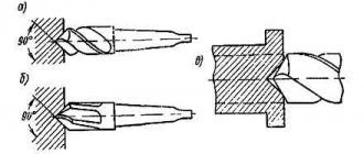
Conical holes of normal sizes (internal cones in adapter bushings, in mounted reamers, countersinks, etc.) should be processed with reamers (Fig. 163), the set of which for a certain type and size of the conical hole being machined (for example, Morse taper No. 4) consists of 3 pcs. Each of these reamers has a conical part corresponding to the size of the hole for which it is intended to process, and a cylindrical shank ending in a square.
On the conical part, grooves are milled to form teeth. The first (grinding) reamer (Fig. 163, a) has a small number of teeth (in the reamer for Morse taper No. 4 there are 6 teeth). They are made in steps with the steps arranged along a helical line. The second reamer (Fig. 163, b) has a significantly larger number of teeth than the first, but also stepped (to separate the removed chips into parts). The third (finishing) reamer (Fig. 163, c) has straight, even teeth; There are slightly more of them than in the second scan.
Rice. 163. Conical reamers
The hole is drilled with a drill with a diameter 0.5-1.0 mm smaller than the smaller diameter of the first reamer. Due to the stepped shape of the teeth of this reamer and their arrangement along a helical line, the reamed hole turns out to be stepped. After the second scan, the steps decrease in size, but their number increases. The last (finishing) reaming removes the steps, and the machined hole is obtained with smooth walls.
A set designed for machining conical holes with small cone slopes sometimes consists of two reamers. Very flat cones are often processed immediately with a finishing reamer.
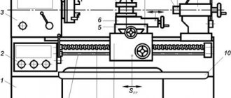
The sweep setting during operation is shown in Fig. 164. The working end 3 of the reamer is inserted into the hole being processed in part 2, fixed in the chuck 1, and the right end is supported by the center 5, inserted into the quill 6 of the tailstock of the machine. A clamp 4 is put on the square end of the reamer, the end of which rests on the upper platform of the caliper. As the reamer moves to the left, the tailstock quill is also moved to the left by the continuous rotation of its flywheel. If the end of the clamp approaches the left edge of the platform, the entire caliper should be moved to the left.
Rice. 164. Reaming a tapered hole
Checking tapered holes. To check conical holes, plug gauges are used (Fig. 165, a). When using such a gauge, chalk or pencil marks are applied to its side surface. If, after the gauge is inserted into the hole being tested and turned several times, the marks are erased along the entire length, the angle of the hole cone is correct. If the marks are erased only on the smaller diameter of the caliber, this means that the cone angle is large. If the cone angle is too small, chalk or pencil lines will be erased only at the large caliber diameter. The diameters of the conical hole are also checked with a plug gauge. With a correctly processed hole, mark B, applied to the plug gauge, should be covered by the part, and the end of the part should not cover mark A (Fig. 165, b). If mark B on the gauge does not reach the end of the part, the hole should be processed additionally, and if mark A goes deep into the part, the latter is defective.
Rice. 165. Plug gauge (a) for checking conical holes and its application (b)
Tool classification
The classification of scans can be carried out according to a large number of different characteristics.
Some types of scans according to GOST
When considering the types of scans, it should be taken into account that the classification is carried out according to GOST:
- The material used in the manufacture of the main part of the product.
- Design features of the cutting edge and tapes, as well as their location relative to each other.
- The type of hole that can be machined.
- Method of fastening in a collar or machine.
- Possibility of adjusting the size of the hole that will be processed.
Manual reaming has its own specific features that allow you to secure the tool in a special wrench. Modern machine reamers have their own design features that must be taken into account when choosing a tool.
Download GOST 7722-77
The most popular options are:
- The sliding reamer has become very widespread, as it can be used to process holes of various diameters. An expanding reamer with a ball allows you to achieve high dimensional accuracy and the required surface roughness.
- Taper shank versions are also widely used due to their high versatility. The teeth can be made in a mounted form.
- A screw reamer may have soldered plates. They are made using hard alloys that can withstand prolonged mechanical stress without overheating.
Sliding reamers
Helical reamer
As previously noted, the tool in question can be used for machining conical holes. The combined reamer can be used to work with the following types of holes:
- Tapered pins.
- Metric cones.
- A thread that is on a conical surface.
- Surfaces made according to the Morse taper standard.
GOST specifies the accuracy class of the sweep. It depends on the geometric parameters and the type of material used in manufacturing.
Step reamers are used to produce higher quality holes. For example, a two-stage reamer can split the stock, increasing surface quality.
According to the method of use, the following product options are distinguished:
- Manual – a design option that is intended for manual processing of parts. As a rule, a wrench is also used with the working part. It is designed to transmit rotation. It is worth considering that the manual version is designed to remove a smaller layer.
- Mechanical - for use with machines or devices that are powered by electricity. Thanks to its use, processing can be significantly accelerated.
Types of metal reamers
Carbide reamers for metal are very widespread today. This is due to the fact that the hard alloys used can withstand long-term use without the surface wearing out. As a rule, it is the wear of the cutting edge that causes a decrease in surface quality.
Download GOST 13598-851672-80
According to the type of hole being machined
The holes being machined can have very different surface geometries. More widespread:
- Cylindrical holes. They are characterized by the fact that two surfaces are parallel to each other.
- Conical holes. In this case, the formed cavity may narrow. In this case, the angle of inclination may differ significantly.
A conical reamer is selected for each workpiece. This is because the tip must conform to the shape of the cone. The conical surface is quite difficult to process, and only by using the appropriate product can the required shape and quality be achieved.
A cylindrical reamer has a simpler shape; a similar tool is found quite often.
Countersinking
All about square hole drills
A countersink is used to process holes that are pre-stamped, cast or drilled. Countersinking can be both preliminary (before deployment) and final processing. In addition to machining holes, countersinks are sometimes used to process the end surfaces of workpieces.
To increase the accuracy of countersinking (especially when processing cast or stamped deep holes), it is recommended to first bore (with a cutter) the hole to a diameter equal to the diameter of the countersink, to a depth approximately equal to half the length of the working part of the countersink.
Countersinks, like drills, are installed on lathes most often in the tailstock or turret.
The difference between countersinking and related operations
Countersinking is similar to reaming holes; the cutting edges of the tool remove excess material from the stenoctium, reduce roughness and increase the diameter. This is a semi-finish operation, which means it is followed by another processing step. Deployment is the final procedure. During countersinking, defects in drilling, stamping and casting are eliminated. In the process, you can slightly adjust the binding to achieve better alignment for the future connection. Accuracy can be increased to 5, and sometimes even to 4th class.
When setting the cutting mode, you need to remember that the thickness of the metal removed during countersinking is equal to half the allowance for a given hole diameter. Compared to drilling, the feed can be made 1.5-2 times larger, but the speed can remain the same. Specific cutting parameters are calculated using formulas given in the regulatory literature.
Since a countersink has greater rigidity compared to a drill, due to the increased number of sharp protrusions, the accuracy of the direction of movement increases, as well as the quality of processing, smoothness and cleanliness of the surface. For comparison, drilling gives a roughness of 20 microns and grades 11–12, countersinking gives a roughness of 2.5 microns, grades 9–11, and reaming gives a roughness of 0.25-1.25 microns and grades 6–9. Quality is the precision of manufacturing a part; as its value increases, tolerances increase and accuracy decreases. If the technological process for processing a product requires both countersinking and reaming, then they are performed in one installation and alignment of the workpiece on the machine.
This type of machining creates recesses to accommodate fasteners flush with the surface of the part. In addition to chamfering, a countersink is used to cut conical-shaped recesses. Another purpose will be to clean and process recesses before installing fasteners; this is done using flat or end countersinks, also called counterbores, which is more correct.
The most widely used on the market are conical countersinks with working angles of 90 and 120º, which create recesses to hide the heads of bolts and screws. In the metalworking industry, countersinks with a flat tip are also used, used for cleaning recesses for fasteners. Countersinks are installed in the same machines as other tools for processing holes for fasteners.
Developments - general information.
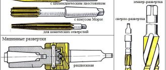
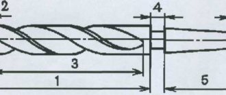
1. General information about sweeps. Reaming is the process of machining holes to achieve improved cleanliness and accuracy. A reamer is a multi-toothed tool that, like a drill and a countersink, during processing rotates around its axis (the main movement) and moves forward along the axis, making a feed movement. Reaming allows you to obtain a hole of the 2-3rd class of accuracy and 7-8th class of cleanliness of the machined surface. 2. Design of reamers. 2.1. Basic structural elements of reamers. Manual and machine reamers (Fig. 1) have the following main parts: working, cutting, calibrating, neck, shank. The purpose of the neck and shank of reamers is the same as that of drills and countersinks. The working part includes cutting and calibrating parts and a guide cone, which serves to protect against damage and facilitate the entry of the reamer into the hole.
Rice. 1. Elements of a) machine and b) manual reamers. The cutting (taking) part of the reamer is a cone, on the surface of which teeth are formed. The calibrating part consists of a cylindrical section and a section with a reverse taper. The front and rear surfaces of the reamer teeth, both on the cutting part and on the calibrating part, are flat. 2.2. Structural elements of the reamer: D – diameter of the reamer; Z – number of teeth; 2φ – angle of the cutting part; interdental grooves, their shape and uneven distribution; tooth profile, α and γ – rear and front angles on the cutting part, rear cone, reamer fastening elements; L is the total length of the sweep. 2.2.1. The diameter of the reamer is the most important structural element, since ultimately the purpose of the reamer is to produce an accurate round hole of certain dimensions. When assigning the diameter of the reamer, it is necessary to take into account the breakdown; reserve for wear; tolerances for the manufacture of the reamer itself. To ensure entry into the hole, the small diameter of the cutting part is made smaller than the diameter of the machined hole by 1.3-1.4 allowances for reaming. The diameter of the reamer at the end of the cutting part and at the cylindrical section of the calibrating part is selected depending on the breaking of the hole during processing, the tolerance for making the hole and the desire to provide the maximum possible margin for wear of the reamer along the diameter. The layout of the tolerance fields for the diameter of the reamer is shown in Fig. 2. The diagram is shown for the case when, during the reaming process, the diameter of the hole increases compared to the actual dimensions of the reamer. Therefore, in order to obtain a hole within the tolerance range, the maximum reaming diameter is taken to be equal to the maximum hole diameter minus the maximum breaking value. The tolerance on the reamer diameter must be chosen so that its provision on grinding and finishing machines does not present any particular difficulties. The amount of hole breaking depends on the size of the workpiece being processed, cutting conditions, the accuracy of manufacturing the reamer and the accuracy of its installation on the machine, etc. In some cases, especially when processing thin-walled parts made of materials with increased ductility and viscosity with worn reamers, a negative effect may be observed breaking the hole. When designing reamers, the approximate maximum value of hole breaking is assumed to be equal to 1/3 of the tolerance for the hole. The specified values for the hole breaking value are determined experimentally.
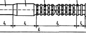
Rice. 2. Layout of tolerance fields for the diameter of the reamer. The diameter at the end of the calibrating part is taken to be less than the diameter of the reamer. The result is a reverse cone. It is generally accepted that the reverse cone on reamers serves to reduce the friction of the reamer on the machined hole, facilitate the withdrawal of the reamer and protect the hole from breaking. For manual reamers, the reduction in diameter towards the shank is 0.010 - 0.015 mm. Due to such a small amount of thinning, the cylindrical section of manual reamers is often not made, and the reverse cone begins immediately after the cutting part. 2.2.2.Number of teeth . The number of reamer teeth is selected depending on the material being processed, the diameter and design of the reamer. As the number of teeth increases, the cleanliness of the holes is improved, but the cross-section of the chip flutes decreases, and they may not be sufficient for free placement and removal of chips. With a large number of teeth and a shallow groove depth, regrinding reamers to smaller sizes becomes difficult. Despite the removal of small layers of metal, the reamers have a relatively small number of teeth (from 6 to 14) for entire machine and hand reamers with a diameter of 3-50 mm. Reamers of a prefabricated structure are made with a smaller number of teeth, since the fastening elements of the insert teeth require adequate space for their placement. Reamers usually have an even number of teeth. This makes it easier to measure their diameter. The uneven distribution of teeth around the circumference has a positive effect on the operation of the reamer, which helps dampen vibrations that occur during operation, especially at increased cutting conditions in conditions of insufficient rigidity of the AIDS system, and improves the cleanliness of the machined surface. To make the final selection of reamer teeth, it is necessary to draw the resulting tooth and groove profile. In reamers with helical teeth, the number of teeth is chosen to be smaller. Depending on the properties of the material being processed and the type of chips being separated, a different number of teeth can be selected. For reamers intended for processing ductile metals, the number of teeth is determined by the formula z = 1.5 root of D + 2 ; for brittle metals z = 1.5 root of D + 4 . 2.2.3. The rake angle γ of the reamers is usually taken equal to zero, since the reamer operates in the zone of small thicknesses of the cut layer, the nature of the cutting process depends mainly not on the rake angle, but on the radius of curvature of the cutting edge. On rough reamers and when processing viscous materials, the rake angle is 5-10°. 2.2.4. The clearance angle is taken small to maintain the strength of the cutting edge. If the clearance angle is taken to be significant, the strength of the edge is reduced and chipping is possible, leading to deterioration in the cleanliness of the hole surface. The sweep ranges from 4-8°. For finishing reams, the angle α is chosen less than for rough reams. 2.2.5.Ribbon width along the cylinder . The teeth on the cutting part are sharpened “to the point”, and on the calibrating part - leaving a cylindrical strip 0.05-0.3 mm wide. When processing viscous metals, in order to avoid sticking of metal particles, the width of the ribbon is reduced to 0.05–0.10 mm. The tape serves to guide the reamer in the hole, facilitates calibration of the hole and facilitates control of the reamer along the diameter. 2.2.6. Plane angle φ. The operation of the reamer is greatly influenced by the angle φ between the reamer axis and the cutting edge, which, with a rake angle equal to zero, runs along the generatrix of the cone of the cutting part. With a change in the angle φ, the relationship between the width and thickness of the cut, the components of the cutting force, and the intensity and nature of tool wear changes. As the angle of the intake cone increases, the axial force increases, making it difficult to advance the reamer. Therefore, for manual reamers, the lead angle is assumed to be small, which also contributes to the smooth entry and exit of the reamer from the hole. Based on experimental data for manual reaming when processing through holes φ = 1 ÷ 2°. During operation, machine reamers are guided better than manual ones, so the length of their cutting part can be shorter and the lead angle larger. When processing cast iron φ = 4÷5°, and when processing steel φ = 12 ÷ 15°. For blind holes, both manual and machine reamers, φ = 45 ÷ 60°. For machine reamers, the value of thinning ranges from 0.04–0.10 mm, with the length of the calibrating part equal to 0.25–0.30 times the diameter of the reamer. On the basis of research and production experience, in recent years, reamers have been developed with a sharply shortened reverse cone length to 3-5 mm and a reduction in diameter at the rear end by 0.5-0.7 mm, which provide the required accuracy and high surface frequency especially when machining short holes. 2.2.7. Profile angles . Processing of chip grooves of reamers is carried out with single-angle (Fig. 3, a) or double-angle (Fig. 3, b) cutters with a profile angle θ = 65 ÷ 110°. For medium and large sizes, a profile with a radial outline of the tooth wall is used, which facilitates the placement of chips in the grooves (Fig. 3, c).
Rice. 3. Reamer groove profiles. When milling, obtaining an uneven pitch with the same tooth width is ensured by changing the depth of the groove by appropriately setting the cutter. Typically, the grooves of reamers are made straight, which simplifies their production and control. For processing holes that are interrupted in length or have longitudinal grooves, reamers with helical teeth are indispensable. Reamers for processing light alloys are also equipped with helical grooves. The angle of inclination of the screw teeth in reamers can reach up to 30-45°. The direction of the screw grooves is made opposite to the direction of rotation of the reamer in order to eliminate self-tightening and jamming of the reamer in the hole. The use of reamers with a large angle of inclination of the helical groove ensures good cleanliness of the machined surface, but at the same time significant feed forces arise. 2.2.8. The length of the working part of the reamer and its total length. The length of the working part and the total length of the reamers are taken according to the relevant standards, and the total length of the reamer depends solely on the depth of the reamed holes and the method of fastening the reamer. If the reamer must have a guide part, then it is necessary to include the length of the guide part in the total length of the reamer. It is recommended to make the length of the working part of the reamer within 0.8 - 3 times the diameter of the reamer. The shorter the working part of the reamer, the easier the reamer cuts, but because of this, the direction of the reamer in the hole and the cleanliness of the surface of the holes sharply deteriorate. If the direction of the reamer in the hole is good (the presence of a guide part), you can reduce the length of its working part. There are disk reamers, which are discs with teeth with a width equal to 0.1 - 0.2 of the diameter of the reamer, mounted on a mandrel with a guide part. 2.2.9. Reamer fastening elements . The reamer is equipped with a connecting part. Mounted reamers most often have a tapered hole with a taper of 1:30 and an additional end keyway. Shank machine reamers have a conical shank with a foot, which is inserted into the corresponding socket of the spindle or a special chuck, or a cylindrical shank. Using hand reamers, a square is made at the end of the shank for working with a crank. Thanks to the hinged connection, the oscillating chuck allows you to compensate for the mismatch between the axis of rotation of the reamer and the axis of the part. Pumping type chucks are not perfect enough, since in their different positions the reamer axis is located differently relative to the axis of the hole. Floating cartridges do not have the disadvantages associated with misalignment of the reamer axis, since the reamer cannot swing, but moves only in the direction perpendicular to the axis, due to which the hole axis is correctly directed. Reamers, the direction of which is carried out by special smooth guides, work better and their durability is higher. Long special reamers, which are used to ream several holes with a common axis, must have a guide part. To ensure free rotation and movement of the guide part in the jig bushings, lubricating grooves should be made on the guide part, otherwise the reamer may jam and even break. 3.Features of the main types of scans. 3.1.Manual cylindrical reamers. The simplest and most common type of manual reamer is a solid cylindrical one with straight grooves (Fig. 4, a). They are usually made from 9ХС chromium steel. The disadvantage of such reamers is the impossibility of adjusting the size after wear of the reamer. In the body 1 of the expanding reamer (Fig. 4, b), made of 9ХС steel, a hole is drilled in the center, at one end of which a thread is cut; in the depth the hole has a conical part. Ball 3 is inserted into the reamer hole and adjusting screw 2 is screwed in. If you start screwing in the screw, it will press on the ball, which will tend to press apart the walls of the hole. In the middle part the reamer body is equipped with slots. As the ball is pressed into the hole, the reamer body expands and increases in diameter, but the increase in diameter occurs only in the central part of the reamer. In the body of a manual sliding reamer (Fig. 4, c), made of structural steel, precise grooves are milled, running in relation to the reamer axis with a slope. Flat knives are inserted into the grooves with a sliding fit. The ends of the knives have angled bevels. Adjustable sliding reamers have significant diameter adjustment limits from 0.5 to 3 mm. These reamers are very convenient for repair work. Adjustable manual reamers are made for holes with a diameter of 10 - 38 mm. Smaller reamers are very difficult to make, and larger reamers are rarely used as hand reamers.
Rice. 4. Types of manual reamers: a – solid, b – expanding, c – sliding. 3.2.Reamers for conical holes. Taper reamers are often used to ream conical holes. The greater the taper angle, the more difficult it is to ream the conical hole with one reamer, and several reamers have to be made. Taper bore reamers operate under harsher conditions than cylindrical bore reamers. A conical reamer cuts with its entire blade and has a calibrating part, since the cutting edges along the entire length come into operation. The kit includes three reamers: roughing, intermediate and finishing. The roughing reamer (Fig. 5, a) is designed to remove a significant allowance; To facilitate the work, the cutting edge is made stepped. A backed screw tooth is cut on the conical generatrix surface of the reamer. The intermediate reamer (Fig. 5, b) has chip separating grooves cut in the form of a thread; Depending on the diameter, the pitch of this thread is different. The finishing reamer (Fig. 5, c) has straight teeth along the entire length of the cutting part.
Rice. 5. Conical reamers. a) roughing, b) intermediate, c) finishing. 3.3.Machine cylindrical reamers. Unlike manual reamers, machine reamers have a short working part and often fewer teeth; they are standardized. Solid reamers can include machine reamers with hard alloys. The body can be made with a tapered shank or with a cylindrical clamping part. Starting from 25 – 30 mm, reamers can be made not with tail ones, but with attachment ones. Mounted reamers are made from alloy steel 9ХС, as well as from high-speed steel. The use of a hard alloy makes it possible to dramatically increase the wear resistance of reamers, as well as to obtain a hole with less surface roughness. All types of machine reamers have one common drawback: they cannot be adjusted in diameter as they wear out. Currently, sliding machine reamers of various designs are becoming widespread. They can be divided into two groups.
- Expanding machine reamers.
- Machine reamers with screwed knives.
A reamer is a finishing tool, so there are special requirements for sharpening it. The cutting edges of the reamer must be very cleanly processed, the surface roughness of the cutting edges of the reamer must be no lower than Ra = 0.32 µm. The reamer must have a sharpened back corner and the front surface of the tooth; First, the front surface of the tooth is sharpened. Sharpening is carried out on a universal sharpening machine.
Rice. 6. Machine reamers. a) with carbide and a conical shank, b) welded from high-speed steel with a conical shank, c) mounted with carbide plates.
Main design elements
Both solid metal and adjustable reamers include three basic design components: the working part, the neck and the shank. The first is designed to form a hole with a given geometry and profile and geometry, and with the help of a shank the rotational force is transmitted, which can be manual or machine (see figure below).
The working part contains cutting blades, which can be straight or spiral. They are separated from each other by grooves. Their number is always even and can vary from 6 to 16. The working part includes the following elements: an intake (cutting) part with a conical slope and a calibrating part with a reverse cone. Immediately behind it there is a neck, which is necessary for the exit of the grinding tool after finishing sharpening the reamer (adjustable ones do not have it). The shank of the manual version ends with a square head for the wrench attachment, while the shank of the machine version is made in the shape of a cone or cylinder. The working part of machine reamers is several times shorter than that of manual reamers, so when cutting it is necessary to apply much more controlled force to them.
During the deployment process, the blades and plates become dull and lose both their cutting properties and their specified size. Therefore, in mass production, prefabricated adjustable products are usually used. In this case, their sharpness is restored by replacing the inserted carbide inserts, and the size is adjusted using a diameter-adjustable body or by sliding out of the inserts using a threaded mechanism. The photo below shows the adjustable scan setting.
This is interesting: Tungsten bar - production and application
Application of sweeps
It is almost impossible to achieve high precision and surface quality when using a conventional drill. This is due to the peculiarities of the working part, which has a relatively small number of cutting edges. The use of the products in question can significantly improve the quality of the hole and bring all indicators to the required levels. The scope of application of the tool is extensive:
- Mechanical engineering industry.
- Production of precision products.
- Manufacturing of household appliances and various electronics.
- Machine tool industry.
Note that the wrench used is suitable for various hand tools. In addition, the machine-type product is suitable for almost all cartridges and can be used when performing intermediate operations.
In conclusion, we note that preference should be given exclusively to products from well-known manufacturers. This can be attributed to the fact that they guarantee high quality production and a long service life of the product. However, due to quality control at each stage of production and the use of high-quality materials, the cost of the product increases significantly.
Device and characteristics
A standard scan consists of the following parts:
- The working part has a direct impact on the material and is formed by longitudinal teeth.
- The transition neck is a cylindrical zone of the tool that acts as a transition link between the previous and next parts.
- Shank - necessary for clamping a tool in a driver or chuck of machinery.
The working part is divided into several zones formed by the edges of the teeth:
- The intake part, at the very beginning of which there is a guide cone. In this zone, each tooth has a sharply sharpened cutting edge that selects material from the inside of the hole.
- The calibrating part is responsible for calibrating the hole. Here the edges of the teeth form a so-called cylindrical strip (flat surface), which increases the dimensional stability of the tool.
- The rear cone is where the teeth join the transition neck.
Between the teeth there are grooves that remove chips.
They are straight (most common) and spiral (helical, preferable when working with discontinuous surfaces).
In the latter case, the direction of the screw formed by the grooves is opposite to the direction of rotation of the tool.
This ensures resistance to seizing and self-tightening.
Material
In the manufacture of reamers, we mainly use tool alloy steel grade 9ХС, as well as high-speed steels P18 and P9.
Dimensions
Cylindrical manual models reach a length of 80 - 360 mm, where the working part occupies 40 - 190 mm.
The diameter of the tool is in the range of 3-50 mm, and the length of the cutting part is 4 – 10 diameters.
The front angle is from 5° to 10°, and the back angle is from 5° to 12°.
The length of the conical manual options is 55 – 170 mm, of which the cutting part occupies 24 – 90 mm.
The maximum and minimum diameters of the cone reach 7.67 - 45.715 mm and 6.39 - 40.978 mm, respectively.
As for machine reamers, in addition to standard options, there are models with an extended working part, the design and dimensions of which are specified in GOST 11175-70.
Reamers with a diameter of 1 – 120 mm with an allowance for finishing are designated by numbers from 1 to 6.
This numbering establishes a correspondence between the nominal diameter of the tool and its maximum deviations.
Teeth
The number of teeth varies from 6 to 14 pieces, however, there are options for 16 teeth, which are used mainly on high-precision equipment.
In general, the number of teeth depends on their own rigidity, and in inverse proportion.
The more of them, the higher the cleanliness of the final hole, but the worse the removal of chips and the lower the strength of each tooth.
Depending on the inclination of the teeth relative to the axis of rotation of the tool, the reamer can be straight-toothed or helical.
In addition, different models may have equal or different pitches, that is, the distance between adjacent teeth.
As for sharpening, there are sharpened (pointed) and backed teeth.
Reamer design
There are a variety of different versions of this cutting tool on sale, all of them are characterized by their specific performance qualities. Making reamers is a rather complex process, since all structural parts must be highly accurate. The design of the reamer allows processing of cylindrical and conical holes. Almost all types of cutting tools have an almost similar design:
- The working part, which is responsible for removing metal. It is represented by a combination of several cutting edges. It is worth considering that sharpening of reamers should be carried out taking into account all the features of the geometry.
- The transition neck is also an important part of the geometry. It is designed to distribute the resulting load.
- The shank is intended for fixing the cutting tool in the driver or chuck. The features of this element determine the reliability of fastening and the scope of application of the product. For example, versions intended for manual use have a special shank suitable for fixation in the driver.
Manual Reamer Design
When looking at the development drawings, they pay most attention to the features of the working part. It consists of several parts:
- The main cutting edge, which removes metal. It can have different shapes; metal with increased precision is used in its manufacture.
- Ribbons designed to remove chips from the cutting site.
- Anterior and posterior surface, occipital. They determine the geometric features of the working part.
The marking determines the main parameters of the tool. In addition to the above elements, I will also highlight the following:
- Rear cone.
- The intake part, which is called the cutting part.
- The part responsible for calibrating the instrument before use.
Drill design
Between all the teeth there are grooves that characterize the cutting edge. In addition, the grooves ensure the formation and removal of chips. Manual versions have a uniform arrangement of teeth over the entire cylindrical surface, thereby ensuring the required processing quality.
How machine deployment works
In order to select machine deployment execution modes, you can use special tables. The initial parameters in this case are the diameter of the hole being formed, the grade of the material being processed, as well as the material from which the reamer is made. The main modes of machine reaming include the cutting speed and the frequency at which the equipment spindle must rotate.
Coolant used
When reaming holes in workpieces made of different materials, you can use the following recommendations for choosing coolant:
- steels belonging to the category of carbon, structural and instrumental - aqueous solution of soap, emulsion, sulfurized oil, mixture of oils;
- cast iron - can be processed without coolant or using kerosene;
- copper – emulsion;
- aluminum - emulsion, mixture of oils, pure kerosene, mixture of kerosene with turpentine oil, rapeseed oil.
- bronze – processed without the use of coolant.
Compositions of coolant used when reaming holes in various materials
Some nuances of machine deployment
It is very important to properly prepare the equipment before machine deployment. Such preparation consists of the following
- The cone of the tool shank and the mounting hole in the machine spindle are thoroughly wiped.
- The reamer is inserted into the spindle in the same way as.
- The workpiece is fixed on the work table of the equipment so that the axis of the hole exactly coincides with the axis of the tool used.
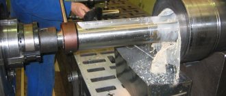
Machining a hole on a machine using a carbide reamer
The deployment process itself, which uses roughing and finishing tools, is performed in the following sequence:
- Having completed drilling the workpiece, the drill in the spindle of the drilling equipment is replaced with a rough reamer.
- Carry out rough deployment.
- The roughing tool is replaced with a finishing tool and the reaming of the hole is repeated.
- After finishing deployment, the tool is removed from the processing zone, the machine’s electric motor is turned off and the result of the work is checked using a plug gauge.