Other GOSTs
GOST 28442-90 Broaches for cylindrical, slotted and faceted holes. Technical specifications GOST 25970-83 Broaches for six-spline holes with a straight-sided profile centered along the inner diameter, combined variable cutting, two-pass. Design and dimensions GOST 25969-83 Combined alternating cutting broaches for six-slotted holes with a straight-sided profile centered along the inner diameter. Design and dimensions GOST 24819-81 Combined variable cutting broaches for six-spline holes with a straight-sided profile centered along the outer diameter. Two-pass. Design and dimensions GOST 24818-81 Combined variable cutting broaches for six-spline holes with a straight-sided profile centered along the outer diameter. Design and dimensions GOST 25157-82 Two-pass broaches for slotted holes with an involute profile with a diameter of 12 and 14 mm, a 1 mm module, centered along the outer diameter. Design and dimensions GOST 25159-82 Two-pass broaches for slotted holes with an involute profile with a diameter of 15 to 90 mm, a module of 1 to 2.5 mm, centered along the outer diameter. Design and dimensions GOST 28050-89 Broaches with a screw-on shank for spline holes with an involute profile with a diameter of 55 to 130 mm, module from 3 to 5 mm, centered along the outer diameter. Design GOST R 50035-92 Broaches with a screw-on shank for splined holes with an involute profile with a diameter of 50 to 120 mm, a module of 1.5 to 2.5 mm, with centering along the outer diameter, combined. Design GOST 28048-89 Broaches with a screw-on shank for splined holes with an involute profile with a diameter of 50 to 120 mm, module from 1.5 to 2.5 mm, centered along the outer diameter. Design GOST 20365-74 Round broaches of variable cutting with a diameter from 14 to 90 mm. Design and dimensions GOST 20364-74 Round broaches of variable cutting with a diameter of 10 to 13 mm. Design and dimensions GOST 25161-82 Two-pass broaches for slotted holes with an involute profile with a diameter of 70 to 90 mm, a module of 3.5 to 5 mm, centered along the outer diameter. Design and dimensions GOST 25160-82 Broaches for slotted holes with an involute profile with a diameter of 45 to 90 mm, a module of 3 to 5 mm, centered along the outer diameter. Design and dimensions
ACCEPTANCE
2.1. Acceptance rules - according to GOST 23726.
2.2. Tests of broaches for average time between failures must be carried out once every three years, for the established failure-free operating time - once a year on at least three broaches.
2.3. Broaches of one (any) standard size of each type of broaches must be tested.
Testing of sharp-slotted broaches may not be carried out.
2.4. Testing of broaches may be carried out at the consumer’s site under production conditions.
CONTROL AND TEST METHODS
3.1. Tests of broaches for operability, mean time between failures and established failure-free operating time must be carried out on machines that meet the standards of accuracy and rigidity established for them, on samples made of steel grade 45 in accordance with GOST 1050 with a hardness of 197 ... 217 HB with a broaching length for holes:
cylindrical - according to GOST 20364, GOST 20365
splined straight-sided - according to GOST 24818 - GOST 24823 or
GOST 25969 - GOST 25974
splined involute - according to GOST 25157 - GOST 25161
faceted - according to GOST 26478 - GOST 26480
Cutting speed - 6 m/min.
3.2. Tests of broaches for performance are carried out on one workpiece with a broaching length according to the standards listed in clause 3.1.
3.3. After the performance test, the teeth should not have crushed or chipped cutting edges and the broach should be suitable for further work.
3.4. Sulfofresol or a three to ten percent (by weight) solution of Ukrinol 1 emulsol in water with a flow rate of at least 5 l/min should be used as a cutting fluid.
3.5. When testing broaches for mean time between failures and established failure-free operating time, the drawn holes are controlled for accuracy by the corresponding limit and complex plug gauges, measuring rollers or wires in accordance with GOST 2475.
3.6. Roughness parameter R
abroached surfaces of workpieces made of steel grade 45 should not be more than, microns, at the holes:
cylindrical with tolerance fields H7 and H8, straight-sided spline and involute
for centering diameters and centering side surfaces of teeth…………………………………………………………………………………………………………………… ………. 2.5
cylindrical with tolerance field H9, straight-sided spline and involute for non-centering diameters and non-centering side surfaces of teeth, sharp spline and faceted………………………………………………………………………………………… ……………………………………………. 5
3.7. The hardness of the broaches must be controlled according to GOST 9013.
3.8. When monitoring linear and angular dimensions, control means must be used that have a measurement error of no more than the values specified in GOST 8.051 when measuring linear dimensions:
35% tolerance - when measuring angular dimensions,
25% tolerance - when measuring runout.
The radial runout tolerance of the broaches and the accumulated error of the circumferential pitch are controlled with a steady rest.
For broaches with a mechanically fastened shank, the radial runout tolerance and the accumulated error of the circumferential pitch are controlled without a shank.
3.9. The appearance of the broach is controlled by inspection using a LP 2.5-4× magnifying glass according to GOST 25706.
3.10. Acceptance values of mean time between failures and established failure-free operating time must be no less than the values indicated in table. 8.
Table 8
| Shape of drawn hole | Cutting pattern | Operating hours, m | |||
| Average to failure | Installed trouble-free | ||||
| Cylindrical for tolerance fields | H7; H8 | Group | 83 | 38 | |
| H9 | 94 | 42 | |||
| Splined straight-sided | Group | 50 | 22 | ||
| Regular | Without chip separating grooves | 35 | 16 | ||
| With chip separating grooves | 24 | 10 | |||
| Spline involute | Group | 59 | 26 | ||
| Regular | Without chip separating grooves | 42 | 19 | ||
| With chip separating grooves | 30 | 14 | |||
| Grannaya | Regular | Without chip separating grooves | 37 | 17 | |
| With chip separating grooves | 26 | 12 | |||
| Sharp-slotted | Regular | Without chip separating grooves | 28 | 13 | |
| With chip separating grooves | 20 | 10 | |||
Litstamp Tools and Equipment
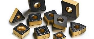
Universal broaches for processing cylindrical, spline, involute, and faceted holes are manufactured with technical requirements regulated by GOST 28442-90. The manufacturing material for this tool is high-speed steel, which ensures a broaching resistance no lower than that made from high-speed steel according to GOST 19265. Also, at the customer’s request, the manufacturing material can be HVG grade steel. The hardness of the teeth according to HRC should be at least 63-66 for high-speed steel and 62-65 for high-speed steel. The broach teeth should not have chipped edges, blockages or burrs. Roughness of the front surface of the teeth Rz 1.6.A universal-purpose, variable cutting broach, the main purpose of which is the processing of cylindrical holes, is manufactured in accordance with GOST 20364-74 and GOST 20365-74 standards. This tool has equal durability of roughing and finishing parts. The diameter of the hole being machined ranges from 10mm to 90mm. The broaching design can be single-pass or double-pass.
A universal-purpose broach, the main purpose of which is the processing of square holes, is manufactured in accordance with the standards GOST 26478-85 - GOST 26480-85. The side of the hole to be machined ranges from 10mm to 41mm. The broaching design can be single-pass or double-pass.
A universal-purpose broach, combined variable cutting for a six-spline hole with a straight-sided profile, is manufactured in accordance with the standards GOST 24818-81 - GOST 24819-81, if centering is performed along the outer diameter, and GOST 25969-83 GOST 25970-83 - with centering along the inner diameter . The broaching design can be single-pass or double-pass.
A universal-purpose broach, combined with variable cutting for processing an eight-slotted hole with a straight-sided profile, is manufactured in accordance with the standards GOST 24820-81 GOST 24821-81, if centering is performed along the outer diameter, GOST 25971-83 - GOST 25972-83 - with centering along the inner diameter . The broaching design can be single-pass or double-pass.
A universal-purpose broach, combined variable cutting for a ten-spline hole with a straight-sided profile, is manufactured in accordance with the standards GOST 24822-81 GOST 24823-81, if centering is performed along the outer diameter, and GOST 25973-83 - GOST 25974-83 - with centering along the inner diameter . The broaching design can be single-pass or double-pass.
A combined variable cutting broach for machining a ten-slotted hole, having a straight-sided profile, is manufactured in accordance with the standards GOST 28044-89 - GOST 28046-89. Centering is performed along the inner diameter. According to their design, they can be one-, two-, three- and four-pass.
A broach for processing keyways, for universal purposes, is manufactured in accordance with the standard GOST 18217-90 - GOST 18220-90. This tool can have chamfered teeth, have a thickened body, and can also be manufactured for processing grooves of increased cleanliness. The technical conditions of keyed broaches are regulated by GOST 16791-80.
A universal-purpose broach for slotted holes with an involute profile is manufactured in accordance with GOST 25157-82 - GOST 25161-82 standards. The broach diameter can range from 12mm to 90mm. The broaching module, depending on its diameter, ranges from 1 to 5 mm. Centering is performed along the outer diameter. The broaching design can be single-pass or double-pass.
A broach with a screw-on shank for processing a spline hole with an involute profile is manufactured in accordance with the standards GOST 28048-89 - GOST 28051-89, as well as GOST R 50035-92 - GOST R 50038-92. The diameter of the hole being machined is from 50mm to 130mm. Centering is performed along the outer diameter. In terms of execution they can be single-pass or double-pass.
Litstamp software sells broaches of its own production, of any design, meeting all the requirements regulated by GOST and GOST R standards. In the production process, only modern technologies, high-precision equipment and high-quality materials are used. As a result, the customer receives the best and most reliable metal-cutting tools at the best prices from the manufacturer.
Previous articles:
- Splined broach
- Keyed broach
Similar articles:
- Angle cutter
- Shaped cutter GOST 9305
- Knurling rollers GOST 12482 - 3291
- Thread rolling rollers GOST 9539-72
- Broaching tool
Next articles:
- Chopping knives
- Prefabricated broaches
- Threaded comb cutters
- Cylindrical cutters
- Double-sided angle cutters
Next page >>
TECHNICAL REQUIREMENTS
1. TECHNICAL REQUIREMENTS
1.1. Characteristics
1.1.1. Broaches must be manufactured in accordance with the requirements of this standard according to working drawings approved in the prescribed manner.
1.1.2. Broaches must be made of high-speed steel in accordance with GOST 19265 or from other grades of high-speed steel, ensuring the durability of broaches not lower than those made of high-speed steel in accordance with GOST 19265.
By agreement with the customer, it is possible to manufacture broaches from steel grade HVG in accordance with GOST 5950.
Broaches made of high-speed steel can be manufactured as one-piece, welded, with a mechanical fastening of the shank, or assembled with mounted bushings.
1.1.3. The shank of welded broaches or mechanically attached to the broach and the mandrel of prefabricated broaches must be made of steel grade 40X in accordance with GOST 4543; nuts in accordance with GOST 11871 for prefabricated broaches are made of steel grade 35 in accordance with GOST 1050.
It is permissible to use other grades of steel of equal or greater strength.
1.1.4. Holes, lack of penetration, burnt metal, cracks and other defects that reduce the strength of the broach are not allowed at the welding site.
1.1.5. The hardness of broaches and parts for them should be HRC:
| teeth and rear guide made of high-speed steel | 63…66 | ||
| teeth made of steel grade HVG | 62…65 | ||
| HSS front guide | 61…66 | ||
| front and rear guides made of HVG steel | 57…65 | ||
| the locking part (from the end to the non-working cone of the lock) of the front shank of welded broaches; | |||
| shank (front and rear) mechanically attached to the broach | 43,5…51,5 | ||
| solid broaches | 43,5…57 | ||
| solid broaches (at customer's request) | 51,5…57,0 | ||
| prefabricated broach mandrels | 32…41,5 | ||
| threads of the front part of broaches with a screw-on shank at a distance of at least 2/3 of the thread length, counting from the end | 32…41,5 | ||
The hardness of the guide part of broaches with a screw-on shank at a length of 50 mm from the lead-in part is not regulated.
1.1.6. The teeth of the broaches should not have blockages, burrs or crumbled edges.
The mating of the radii of the tooth cavity, including at the junction of the bushings of prefabricated broaches, should not have ledges visible to the eye.
On the smooth front guide of the broaches for spline holes, marks from the grinding wheel are allowed (when grinding splined or chamfered teeth).
Traces from straightening are allowed on the broach.
1.1.7. Center holes are shapes B, R or T according to GOST 14034.
Broaches with a shank with a diameter of 18 mm or less are allowed to be manufactured with center holes of shape A.
Tolerance field for the length of the conical surface of the center holes H16.
1.1.8. The roughness parameters of the surfaces of broaches according to GOST 2789 should be, microns, no more than:
| front and rear surfaces and strips of broach teeth for slotted and faceted holes; | |||
| the rear surface of roughing, transition, finishing and calibrating teeth, made with a ribbon; | |||
| ribbons on roughing, transition and finishing teeth of broaches for cylindrical holes; | |||
| front surface of broach teeth for cylindrical holes with tolerance fields H7 and H8 | 1,6 | ||
| H9 | 3,2 | ||
| the rear surface of the calibrating teeth, made without a ribbon; ribbons on the calibrating teeth of broaches for cylindrical holes with tolerance fields H7 and H8 | 0,8 | ||
| H9 | 1,6 | ||
| working side surfaces of spline teeth, ribbons of teeth on the faces of faceted broaches (with a generator cutting scheme), corner surfaces of chamfered teeth, side surfaces of splined and faceted front and rear guides | 3,2 | ||
| radius surfaces at the front surface, chip separating grooves, fillets, non-working (undercut) side surface of spline teeth; the rear surface of the teeth on the faces of the faceted broaches (with a generator cutting scheme) | 6,3 | ||
| surface of the curved back of the tooth (at customer’s request) | 6,3 | ||
| smooth cylindrical surfaces of the front and rear guides; seating surface for bushings and surfaces of the supporting end of the mandrel of prefabricated broaches, seating surface of the hole and surfaces of the supporting ends of cutting bushings and guides | 0,63 | ||
| the outer diameter of the splined and faceted front and rear guides, the seating surface of the cylindrical part of the shank, the conical surface for the cams and the centering shoulder of the threaded connection of the broach for the screw-on shank | 1,25 | ||
| recess surfaces in bushings and guides of prefabricated broaches, non-working longitudinal grooves on faceted broaches | 10 | ||
| surfaces of the non-working ends of the broach, the non-working journal between the seating surface of the shank and the front guide, the non-working journal and the non-working cone of the lock | 5 | ||
| other surfaces | 2,5 | ||
1.1.9. The width of the cylindrical strip on the calibrating teeth of the broaches should be from 0.2 to 0.6 mm. Calibrating teeth of broaches for cylindrical holes can be made without tapes.
A cylindrical strip with a width of no more than 0.05 mm is allowed on the rear surface of roughing, transition and finishing teeth.
1.1.10. The sides of the teeth of broaches for splined straight-sided holes with a height of more than 1.5 mm must be made with an undercut.
The width of the ribbon on the sides of the teeth should not be more than 1 mm.
A tooth shape without a side band is allowed.
At the customer's request, it is possible to manufacture all broach teeth without undercutting the sides.
1.1.11. The width of the ribbon along the edges of the teeth of the broaches for faceted holes should be 0.6-1.0 mm.
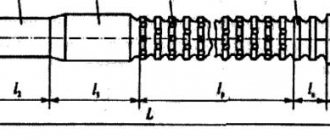
1.1.12. Maximum deviations of the total length of broaches: up to 1000 mm ±3 mm; St. 1000 mm ±4 mm.
Maximum deviations of the distance to the first tooth are ±5 mm. For broaches with a screw-on shank, the maximum deviations refer to the dimensions of the broach without a shank.
1.1.13. Unspecified maximum deviations of broach dimensions: H16, h16, ±.
1.1.14. Dimensions and maximum deviations of shanks are in accordance with GOST 4044.
1.1.15. The maximum deviations of tooth diameters with a rise per tooth of more than 0.02 mm in diameter must correspond to the values specified in Table 1.
Table 1
mm
| Nominal tooth diameter | Limit deviations of tooth diameters when lifting by tooth diameter | |||
| St. 0.02 to 0.04 | St. 0.04 to 0.08 | St. 0.08 to 0.16 | St. 0.16 | |
| Up to 50 | -0,010 | -0,010 | -0,016 | -0,020 |
| up to 120 | -0,016 | -0,016 | -0,020 | |
| St. 120 to 180 | 0,020 | |||
| St. 180 | -0,025 | |||
1.1.16. The maximum deviations of the diameters of teeth with a rise per tooth in diameter of 0.02 mm or less and the calibrating teeth of finishing broaches for cylindrical holes and the centering diameters of finishing broaches for splined holes with straight-sided and involute profiles must correspond to the values specified in Table 2.
table 2
mm
| Nominal tooth diameter | Maximum deviations of the diameters of teeth with a rise per tooth in diameter of 0.02 mm or less and calibrating teeth of broaches for tolerance fields | ||
| H7 | H8 | H9 | |
| 10 | -0,005 | -0,005 | -0,008 |
| 10 to 18 | -0,008 | -0,010 | |
| 18 to 30 | -0,012 | ||
| 30 to 50 | -0,007 | -0,010 | -0,016 |
| 50 to 80 | -0,008 | -0,012 | |
| 80 to 120 | -0,010 | -0,014 | -0,020 |
| St. 120 to 180 | -0,016 | ||
| St. 180 | -0,012 | ||
1.1.17. The maximum deviations of the diameters of calibrating teeth and teeth with a rise per tooth in diameter of 0.02 mm or less of broaches for sharp-slotted and faceted holes, non-centering diameters of splined straight-sided and involute holes and rough broaches must correspond to the maximum deviations of the diameters of cutting teeth according to Table 1.
1.1.18. The maximum deviations of the tooth thickness of finishing broaches for slotted holes with a straight-sided profile must correspond to the values specified in Table 3.
Table 3
mm
| Bushing cavity width | Maximum deviations of the tooth thickness of broaches for tolerance fields for the width of the bushing cavity | ||
| F8; H8 | D9 | F10; D10; Js10 | |
| Until 3 | -0,005 | -0,008 | -0,010 |
| St. 3 to 6 | -0,008 | -0,010 | -0,012 |
| St. 6 to 10 | -0,015 | ||
| St. 10 to 18 | -0,010 | -0,012 | |
| St. 18 | -0,015 | -0,018 | |
The maximum deviations in the tooth thickness of rough broaches are minus 0.02 mm.
1.1.19. The maximum deviations of dimensions along the rollers or wires when checking the profile of the side surfaces of the teeth of finishing broaches for spline holes with an involute profile must correspond to the values indicated in Table 4.
Table 4
mm
| Module | Pitch circle diameter | Maximum dimensional deviations for rollers or wires for tolerance fields for the width of the bushing cavity | |||
| 9N | 11N | ||||
| Large and medium roller or wire | Smaller roller or wire | Large and medium roller or wire | Smaller roller or wire | ||
| From 1 to 1.5 | Up to 25 | -0,010 | -0,012 | -0,016 | -0,024 |
| St. 25 | -0,012 | -0,018 | |||
| St. 1.5 to 4 | Up to 50 | -0,016 | -0,028 | ||
| Over 50 | -0,014 | -0,020 | |||
| St. 4 to 6 | Up to 100 | -0,020 | -0,032 | ||
| St. 100 | -0,016 | -0,024 | |||
| St. 6 to 10 | Up to 100 | -0,022 | |||
| St. 100 | -0,018 | ||||
Maximum dimensional deviations along rollers or wires when checking the profile of rough involute broaches must correspond, mm:
| for module up to 2.5 mm minus 0.03, |
| St. 2.5 mm minus 0.04 |
1.1.20. The maximum dimensional deviations for rollers or wires when checking the profile of sharp-slotted broaches is minus 0.02 mm.
1.1.21. Direct taper of dimensions along rollers and wires on involute and sharp-slotted broaches is not allowed.
1.1.22. The reverse slope along the edges of the teeth along the entire length of the cutting part of the faceted broach must be at least 0.01 mm per side.
1.1.23. The maximum size deviations between the edges of the cutting and calibrating teeth of faceted broaches in two sections (on the first and last faceted teeth) are minus 0.02 mm.
For an odd number of faces, the indicated maximum deviations refer to the diameter of the circle inscribed in the polyhedron.
1.1.24. Maximum deviations of the diameter of the round smooth front guide and the round smooth part of the splined and faceted front guide are according to e8.
Maximum deviations of the outer diameter of the splined and faceted front guide - according to h10.
Maximum deviations of the tooth thickness of the splined straight-sided front guide - minus 0.02 mm, the size along the rollers or wires of the splined involute front guide - minus 0.05 mm, the size between the faces (or the diameter of the inscribed circle with an odd number of faces) of the faceted front guide - according to e8 .
1.1.25. The maximum deviations of the diameter of the rear guide of the broaches for cylindrical holes and the round smooth rear guide located behind the round teeth of the combined spline broaches are f7, the round rear guide of the faceted broaches is minus 0.1 mm.
Maximum deviations of the outer diameter of the splined and faceted rear guide - according to h11.
1.1.26. Maximum deviations of the diameters of the mating centering surfaces of the broach with a screw-on shank:
broaches - on f7
shank - according to H9
1.1.27. The tolerance range of the broach thread with a screw-on shank is 8g, that of the shank is 7H.
1.1.28. Maximum deviations of fillet width: ±0.5 mm, chip separating grooves +0.5 mm.
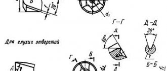
1.1.29. Maximum deviations of tooth profile radii, mm:
| backrest at value | up to 5 m m ±1 | |
| St. 5 mm ±2 | ||
at the transition from the front surface to the back with the value:
| up to 1.5 mm | minus 0.5 | ||
| St. 1.5 to 5 mm | minus 1.0 | ||
| St. 5 mm | minus 2.0 | ||
By agreement with the customer, it is possible to design a tooth profile with a straight back and a cylindrical cavity bottom.
1.1.30. The accumulated error in the circumferential pitch of the teeth of finishing broaches for spline holes with a straight-sided profile with a diameter of up to 80 mm should not exceed the values specified in Table 5. For broaches with a diameter over 80 mm, the values of 0.010 and 0.012 mm indicated in Table 5 increase to 0.016 mm.
Table 5
mm
| Bushing cavity width | Accumulated error of the circumferential pitch of the teeth of straight-sided broaches for tolerance fields on the width of the bushing cavity | ||
| H8; F8; Js10 | D9; F10 | D10 | |
| Until 3 | 0,010 | 0,012 | 0,012 |
| St. 3 to 6 | 0,016 | ||
| St. 6 to 10 | 0,016 | 0,020 | |
| St. 10 to 18 | 0,012 | 0,020 | 0,025 |
| St. 18 | 0,016 | 0,025 | |
The accumulated error in the circumferential pitch of the teeth of rough straight-sided broaches should not exceed, mm:
| for bushing cavity width | 0,015 | |
| St. 6 mm 0.025 | ||
1.1.31. The accumulated error in the circumferential pitch of the teeth of finishing broaches for spline holes with an involute profile should not exceed the values specified in Table 6. rough broaches - values indicated in Table 6, column 11H.
Table 6
mm
| Module | Pitch circle diameter | Accumulated error of the circumferential pitch of the teeth of involute broaches for tolerance fields on the width of the bushing cavity | |
| 9N | 11N | ||
| From 1 to 1.5 | Up to 25 | 0,012 | 0,020 |
| St. 25 | 0,016 | 0,025 | |
| St. 1.5 to 4 | Up to 100 | ||
| St. 100 | 0,020 | 0,032 | |
| St. 4 to 10 | Up to 50 | 0,016 | 0,025 |
| Over 50 | 0,020 | 0,032 | |
1.1.32. The accumulated error in the circumferential pitch of sharp spline broaches should not exceed 0.02 mm.
1.1.33. The parallelism tolerance relative to the axis of the centers for 500 mm of the length of the splined part of the broaches should not exceed, mm:
| lateral surfaces of splined straight-sided teeth of finishing broaches with the width of the cavity | |||
| bushings up to 6 mm | 0,010 | ||
| St. 6 mm | 0,012 | ||
| rough broaches | 0,020 | ||
| axis of symmetry of involute teeth for the tolerance range for the width of the cavity | |||
| bushings 9H | 0,010 | ||
| 11N | 0,015 | ||
| rough broaches | 0,020 | ||
| axis of symmetry of sharp spline teeth | 0,015 | ||
1.1.34. The symmetry tolerance of the tooth in the cross section relative to the axis of the centers should not exceed, mm:
| for straight-sided spline broaching with tooth thickness tolerance | |||
| up to 0.008 mm | — T 0.010 | ||
| St. 0.008 mm | — within the tolerance for tooth thickness; | ||
for involute broaching for tolerance range
| to the width of the bushing cavity 9H | — T 0.020 |
| 11N | — T 0.030 |
| rough broaches | — T 0.030 |
1.1.35. The tolerance for radial runout relative to the axis of the centers of teeth with a rise per tooth in diameter of 0.02 mm or less and calibrating teeth of finishing broaches for cylindrical holes and the same teeth for centering diameters of spline holes with a straight-sided and involute profile should not exceed:
| with tooth diameter tolerance | up to 0.008 mm - 0.010 | ||
| » » | St. 0.008 mm - within the diameter tolerances specified in Table 2. | ||
1.1.36. Tolerance of radial runout relative to the axis of the centers: working surfaces (cutting teeth, shanks and guides) of sharp spline and faceted broaches;
teeth with a rise per tooth in diameter of more than 0.02 mm, shanks and guide broaches for cylindrical, splined straight-sided and involute holes are installed depending on the total length based on the broach for every 100 mm of length, mm:
| broaches for cylindrical holes | 0,004 | ||
| slotted straight-sided and involute holes | 0,005 | ||
| sharp-slotted and faceted holes with a broach length not exceeding 40 diameters | 0,005 | ||
| St. 40 diameters | 0,006 | ||
| rough broaches | 0,006 | ||
1.1.37. The tolerance of radial runout relative to the axis of the centers of the calibrating teeth of sharp-splined and faceted broaches, calibrating teeth for non-centering diameters of straight-sided and involute splined holes and calibrating teeth of rough broaches must be within the tolerances for the corresponding tooth diameter.
1.1.38. The runout tolerance relative to the axis of the centers of the conical surface under the cams in the direction perpendicular to it should not exceed 0.1 mm.
1.1.39. In areas of broaches where fillets are made on all round teeth, the blade of subsequent teeth must overlap the fillet of previous teeth by at least 0.5 mm on each side.
1.1.40. Maximum angle deviations:
| rake angle of all teeth | +2° -1° | ||
| clearance angle of roughing, transition, finishing and chamfering teeth | ±30′ | ||
| rear angle of finishing teeth (except ) | +30′ | ||
| clearance angle of fillets and chip separating grooves | ±1° | ||
| rear angle of calibrating teeth | ±15′ | ||
| undercut angle of the auxiliary cutting edge of splined straight-sided broaches | +1° | ||
| half angle of the cavity of the sharp spline profile of the broach | ±15′ | ||
| the angle between the edges of the broach, related to the width of the edge | ±0.02 mm. | ||
In the case when the rake angle is in the range from 0° to 2°, its maximum deviation is set to +1°.
1.1.41. The average time between failures and the established failure-free operating time of broaches made of high-speed steel grades R6M5 and R12F3 under the conditions given in Section 3 must be no less than the values specified in Table 7.
Table 7
| Shape of drawn hole | Cutting pattern | Operating hours, m | |||
| Average to failure | Installed trouble-free | ||||
| Cylindrical for tolerance fields | H7; H8 | Group | 79 | 36 | |
| H9 | 89 | 40 | |||
| Splined straight-sided | Group | 47 | 21 | ||
| Regular | Without chip separating grooves | 33 | 15 | ||
| With chip separating grooves | 23 | 10 | |||
| Spline involute | Group | 56 | 25 | ||
| Regular | Without chip separating grooves | 40 | 18 | ||
| With chip separating grooves | 28 | 13 | |||
| Grannaya | Regular | Without chip separating grooves | 35 | 16 | |
| With chip separating grooves | 25 | 11 | |||
| Sharp-slotted | Regular | Without chip separating grooves | 27 | 12 | |
| With chip separating grooves | 19 | 9 | |||
Correction factor for the mean time between failures and the established failure-free operating time of broaches made of steel grades:
| R18, R12F5 | 1,1 | ||
| R9K10 | 1,3 | ||
| R6M5K5, R6F2K8M5 | 1,5 | ||
| HVG | 0,5 | ||
1.1.42. The criterion for broaching failure is that the roughness parameter of the machined surface exceeds the permissible value or that the dimensions of the broached hole exceed the tolerance range.
1.2. Labeling and packaging
1.2.1. The following must be clearly marked on the shank:
1) trademark of the manufacturer,
2) broach designation (last four digits),
3) year of manufacture,
4) steel grade of the working part of the broach,
5) number of the broach pass, if the broach is intended for use as a set,
6) an image of the state Quality Mark when it is assigned in the manner established by the State Standard of the USSR.
It is allowed to apply the state Quality Mark only on the label.
At the customer's request, the following are additionally marked:
7) diameter and designation of the tolerance field of a cylindrical hole, designation of a splined straight-sided bushing according to GOST 1139 or an involute sleeve according to GOST 6033, or the size between the faces (or the diameter of a circle inscribed in a polyhedron, with an odd number of faces) and designation of the tolerance field or maximum deviations,
outer diameter and cavity angle of the profile of the sharp spline bushing,
stretch length limits.
1.2.2. Broaches must be accompanied by a passport in accordance with GOST 2.601.
1.2.3. Packing of broaches is in accordance with GOST 18088.