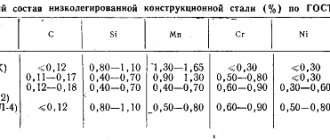
Exact. welding
Hard modes
Hard modes provide higher performance and less power consumption. Due to the fact that the surface of the parts under the electrodes heats up relatively less under harsh conditions, the electrodes heat up less and, despite the increase in pressure, their consumption decreases. The depth2 of indentation at the welding site and warping of the product are noticeably reduced. In general, hard modes are advisable, first of all, in mass production, where the gain in productivity and energy consumption will fully compensate for the additional costs associated with the acquisition, operation and power supply of more powerful equipment.
Current strength and density.
As the thickness of the sheets being welded increases, the current strength should increase. For welding low-carbon steels of medium thickness on serial machines, the approximate selection of current strength l can be carried out according to the following relationship:
l=6500qa,
Where q is the thickness of the sheets being welded in mm.
When welding sheets of different thicknesses, the choice of parameters is made under the condition that there is sufficient heating and deformation of the thinner sheet. Therefore, in the given relationship and in subsequent ones, the value of q is related to a thinner sheet.
Current density I for hard modes is selected within the range of 120 - 360 d/Lm*, for soft modes 80 - 160 A mm2.
With increasing sheet thickness, the density is then/? decreases. When the metal of the parts being welded has increased thermal and electrical conductivity, the current density should increase. Thus, when welding aluminum or its alloys, the current density sometimes reaches 1000 A/mm2 and higher. As mentioned earlier, the current density should be selected higher when, for some reason, the pressure is assumed to be increased.
Resistance spot welding
Heating time
Like current, heating time (tcs) increases with increasing part thickness. Approximately for welding low-carbon steel at hard conditions, the heating time can be selected according to the ratio
tce — (0.1 -f-0.2) q sec.,
where q is the thickness of the thinner sheet in mm.
It is not recommended to take a shorter heating time, since random, even minor errors in the operation of the time regulator can cause serious deviations from the required heating and welding quality.
For welding sheets up to 3 mm thick in soft modes, the heating time can be selected according to the ratio.
I = (0.8×1) q sec.
Heating for too long can cause overheating of the metal in the welding zone.
For welding metals with high thermal conductivity, the welding time is assumed to be short (at high current strength); when welding hardening steels, on the contrary, in order to avoid the formation of hardening cracks during rapid cooling, the heating time often has to be increased (with a corresponding decrease in current).
Spot welding progress
Basic physical parameters for resistance welding
The main parameters of contact welding modes are the current strength, the duration of the flow and the force with which the parts being connected are compressed:
- Welding current strength . Measurements of this parameter are carried out in Amperes or kilo-Amps, measurements are made using special instruments.
- Compression force for welded parts . Measured in decaNewtons. Measurements are also made using special equipment.
- Duration of welding current flow . It is measured in seconds and is timed.
- In rare cases, forging force may also be applied to compact the weld core..
Pressure
The choice of pressure (P) is made depending on the thickness, condition and material of the workpieces, as well as on the nature of the adopted heating mode.
For welding low-carbon steel, the pressure depending on the thickness is selected according to the formula
P=(60×200)q kg.
where q is the thickness in mm.
The specific pressure has a limit of 3x10 kg/mm2.
Mild hot-rolled steel can be coupled at lower pressures. Cold-rolled steel, which has received increased work hardening, requires a slight increase in pressure (by 20-30%). When the workpieces are poorly straightened and have warping, then before tightly squeezing the sheets in the Siamese area, it is necessary to straighten them under the electrodes. The total force required in this case must be increased, especially for larger thicknesses. So, for sheets with a thickness of 3-6 mm, this additional force alone is 100-400 ke. For the same reason, the force should also increase when the points are located in those places of the welded unit where squeezing the sheets is difficult (near the ribs and other stiffeners, and at the places where the parts meet at a radius, etc.).
The specific pressure increases with the strength of the metal being welded. When welding low-alloy steels, it can be 120-160% of the specific pressure for low-carbon steel; when welding austenitic and heat-resistant steels and alloys, it increases by 2-3 times.
- Electrode diameter. The electrode diameter (d) determines the current density, specific pressure and degree of cooling intensity of the surface of the part.
- The diameter of the electrode has a relatively small effect on the electrical resistance of the welding zone, only at the final stage of heating, when complete contact of the surfaces of the electrode and the part is achieved.
- Therefore, during prolonged heating, the influence of the electrode diameter is more pronounced. The diameter of the electrode increases with the thickness of the parts.
- For thicknesses up to 3 mm, the diameter of the electrode is calculated using the following formula:
D=2q+3mm,
where q is the thickness of the thinner sheet.
For parts with greater thickness, the calculation is carried out using the formula
Changing the diameter of the electrode is often used to equalize the heat when welding parts that are unequal in thickness or type of metal.
During the welding process, under the influence of strong heat and heavy mechanical load, the working part of the electrode changes with the formation of a mushroom-shaped thickening, and the surface becomes contaminated with metal oxides. An increase in the actual diameter of the electrode at constant current and compression force means a decrease in current density and specific pressure. As a result, the heating intensity in the welding contact is greatly reduced, and metal compaction becomes more difficult and welding may be of poor quality. In addition, contamination of the surface of the electrodes can cause an increase in contact resistance, overheating and even melting of the surface of the sheets. It is generally believed that wear-related increases in diameter by more than 10% are no longer acceptable. Such electrodes must be cleaned with a file, a special device, or sharpened.
Resistance spot welding
Spot welding is a type of resistance welding. With this method, heating the metal to its melting temperature is carried out by heat, which is generated when a large electric current passes from one part to another through the place of their contact. Simultaneously with the passage of current and some time after it, the parts are compressed, resulting in mutual penetration and fusion of heated areas of the metal. Resistance spot welding
Features of resistance spot welding are: short welding time (from 0.1 to several seconds), high welding current (more than 1000A), low voltage in the welding circuit (1-10V, usually 2-3V), significant force compressing the welding site (from several tens to hundreds of kg), a small melting zone.
Spot welding is most often used for overlapping sheet metal workpieces, and less often for welding rod materials. The range of thicknesses welded by it ranges from a few micrometers to 2-3 cm, but most often the thickness of the welded metal varies from tenths to 5-6 mm.
Spot welding of rods
In addition to spot welding, there are other types of resistance welding (butt, seam, etc.), but spot welding is the most common. It is used in the automotive industry, construction, radio electronics, aircraft manufacturing and many other industries. During the construction of modern airliners, in particular, several million weld spots are produced.
Well-deserved popularity
The great demand for spot welding is due to a number of advantages that it has.
These include: no need for welding materials (electrodes, filler materials, fluxes, etc.), minor residual deformations, simplicity and convenience of working with welding machines, neat connections (virtually no weld), environmental friendliness, cost-effectiveness, susceptibility to easy mechanization and automation, high productivity. Automatic spot welders are capable of performing up to several hundred welding cycles (welded spots) per minute. Disadvantages include the lack of sealing of the seam and stress concentration at the welding point. Moreover, the latter can be significantly reduced or even eliminated using special technological methods.
Sequence of processes for resistance spot welding
The entire spot welding process can be divided into 3 stages.
- Compression of parts causing plastic deformation of microroughnesses in the electrode-part-part-electrode chain.
- Turning on a pulse of electric current, leading to heating of the metal, its melting in the joint zone and the formation of a liquid core. As current passes, the core increases in height and diameter to its maximum size. Bonds are formed in the liquid phase of the metal. In this case, plastic settlement of the contact zone continues to its final size. Compression of the parts ensures the formation of a sealing belt around the molten core, which prevents metal from splashing out from the welding zone.
- Turning off the current, cooling and crystallization of the metal, ending with the formation of a cast core. When cooling, the volume of the metal decreases and residual stresses arise. The latter are an undesirable phenomenon that is combated in various ways. The force compressing the electrodes is released with some delay after the current is turned off. This provides the necessary conditions for better crystallization of the metal. In some cases, in the final stage of resistance spot welding, it is even recommended to increase the clamping force. It provides forging of metal, eliminating inhomogeneities in the seam and relieving stress.
Resistance spot welding steps
At the next cycle everything repeats again.
Basic parameters of resistance spot welding
The main parameters of resistance spot welding include: the strength of the welding current (IW), the duration of its pulse (tW), the compression force of the electrodes (FW), the size and shape of the working surfaces of the electrodes (R - for a spherical shape, dE - for a flat shape). For better clarity of the process, these parameters are presented in the form of a cyclogram reflecting their change over time.
Changing parameters over time
There are hard and soft welding modes. The first is characterized by high current, short duration of the current pulse (0.08-0.5 seconds depending on the thickness of the metal) and high compression force of the electrodes. It is used for welding copper and aluminum alloys with high thermal conductivity, as well as high-alloy steels to maintain their corrosion resistance.
In the soft mode, the workpieces are heated more smoothly with a relatively low current. The duration of the welding pulse ranges from tenths to several seconds. Soft modes are shown for steels prone to hardening. Basically, it is soft modes that are used for resistance spot welding at home, since the power of the devices in this case may be lower than for hard welding.
Dimensions and shape of electrodes
. With the help of electrodes, direct contact of the welding machine with the parts being welded is carried out. They not only supply current to the welding zone, but also transmit compressive force and remove heat. The shape, size and material of the electrodes are the most important parameters of spot welding machines.
Depending on their shape, electrodes are divided into straight and shaped. The first ones are the most common; they are used for welding parts that allow free access of electrodes to the welded area. Their dimensions are standardized by GOST 14111-90, which sets the following diameters of electrode rods: 10, 13, 16, 20, 25, 32 and 40 mm.
According to the shape of the working surface, there are electrodes with flat and spherical tips, characterized by diameter (d) and radius (R) values, respectively. The contact area of the electrode with the workpiece depends on the values of d and R, which affects the current density, pressure and size of the core. Electrodes with a spherical surface have greater durability (they can make more points before resharpening) and are less sensitive to distortions during installation than electrodes with a flat surface. Therefore, it is recommended to manufacture electrodes used in clamps with a spherical surface, as well as shaped electrodes that work with large deflections. When welding light alloys (for example, aluminum, magnesium), only electrodes with a spherical surface are used. The use of flat surface electrodes for this purpose results in excessive indentations and undercuts on the surface of the points and increased gaps between parts after welding. The dimensions of the working surface of the electrodes are selected depending on the thickness of the metals being welded. It should be noted that electrodes with a spherical surface can be used in almost all cases of spot welding, while electrodes with a flat surface are very often not applicable.
Recommended electrode sizes
* - in the new GOST, instead of a diameter of 12 mm, 10 and 13 mm were introduced.
The landing parts of the electrodes (places connected to the electrical holder) must ensure reliable transmission of the electrical impulse and clamping force. They are often made in the form of a cone, although there are other types of connections - along a cylindrical surface or thread.
The material of the electrodes is very important, determining their electrical resistance, thermal conductivity, heat resistance and mechanical strength at high temperatures. During operation, the electrodes heat up to high temperatures. The thermocyclic operating mode, together with a mechanical variable load, causes increased wear of the working parts of the electrodes, resulting in a deterioration in the quality of the connections. To ensure that the electrodes are able to withstand harsh operating conditions, they are made from special copper alloys that have heat resistance and high electrical and thermal conductivity. Pure copper is also capable of working as electrodes, but it has low durability and requires frequent regrinding of the working part.
Welding current strength
. Welding current strength (ICW) is one of the main parameters of spot welding. Not only the amount of heat released in the welding zone depends on it, but also the gradient of its increase over time, i.e. heating rate. The dimensions of the welded core (d, h and h1) also directly depend on ISV, increasing in proportion to the increase in ISV.
Welding core
It should be noted that the current that flows through the welding zone (ICB) and the current flowing in the secondary circuit of the welding machine (I2) differ from each other - and the greater, the smaller the distance between the welding points. The reason for this is the shunt current (Ish), flowing outside the welding zone - including through previously completed points. Thus, the current in the welding circuit of the device must be greater than the welding current by the amount of the shunt current:
I2 = IСВ + Iш
Circuit for shunting current through a previously welded point
To determine the strength of the welding current, you can use different formulas that contain various empirical coefficients obtained experimentally. In cases where an exact determination of the welding current is not required (which is most often the case), its value is taken from tables compiled for different welding modes and different materials.
Modes of spot welding of low-carbon steels
Increasing the welding time allows welding with currents much lower than those given in the table for industrial devices.
Welding time
. Welding time (tSV) refers to the duration of the current pulse when performing one weld point. Together with the current strength, it determines the amount of heat that is released in the connection area when an electric current passes through it.
With an increase in tСВ, the penetration of parts increases and the dimensions of the molten metal core (d, h and h1) increase. At the same time, heat removal from the melting zone increases, parts and electrodes heat up, and heat dissipates into the atmosphere. When a certain time is reached, a state of equilibrium can occur in which all the supplied energy is removed from the welding zone without increasing the penetration of parts and the size of the core. Therefore, increasing tSV is advisable only up to a certain point.
When accurately calculating the duration of the welding pulse, many factors must be taken into account - the thickness of the parts and the size of the weld point, the melting point of the metal being welded, its yield strength, heat accumulation coefficient, etc. There are complex formulas with empirical dependencies, which, if necessary, carry out calculations.
In practice, most often the welding time is taken from tables, adjusting the accepted values in one direction or another, if necessary, depending on the results obtained.
Compression force
. The compression force (FCF) influences many processes of resistance spot welding: the plastic deformations occurring in the joint, the release and redistribution of heat, the cooling of the metal and its crystallization in the core. With an increase in FSW, the deformation of the metal in the welding zone increases, the current density decreases, and the electrical resistance in the electrode-part-electrode section decreases and stabilizes. Provided the core dimensions remain unchanged, the strength of the welded points increases with increasing compression force.
When welding in hard modes, higher values of FSV are used than in soft welding. This is due to the fact that with increasing rigidity, the power of current sources and the penetration of parts increases, which can lead to the formation of splashes of molten metal. A large compression force is precisely intended to prevent this.
As already noted, in order to forge the weld point in order to relieve stress and increase the density of the core, the technology of resistance spot welding in some cases provides for a short-term increase in the compression force after turning off the electrical pulse. The cyclogram in this case looks like this.
Changing the compression force during spot welding
When manufacturing the simplest resistance welding machines for home use, there is little reason to make accurate calculations of parameters. Approximate values for electrode diameter, welding current, welding time and compression force can be taken from tables available in many sources. You just need to understand that the data in the tables is somewhat overestimated (or underestimated, if you take into account the welding time) compared to those that are suitable for home devices, where soft modes are usually used.
Preparing parts for welding
The surface of parts in the area of contact between parts and at the point of contact with electrodes is cleaned of oxides and other contaminants.
If cleaning is poor, power losses increase, the quality of connections deteriorates and wear of the electrodes increases. In resistance spot welding technology, sandblasting, emery wheels and metal brushes are used to clean the surface, as well as etching in special solutions. High demands are placed on the surface quality of parts made of aluminum and magnesium alloys. The purpose of preparing the surface for welding is to remove, without damaging the metal, a relatively thick film of oxides with high and uneven electrical resistance.
Spot Welding Equipment
The differences between existing types of spot welding machines are determined mainly by the type of welding current and the shape of its pulse, which are produced by their power electrical circuits. According to these parameters, resistance spot welding equipment is divided into the following types:
- AC welding machines;
- low-frequency spot welding machines;
- capacitor type machines;
- DC welding machines.
Each of these types of machines has its own advantages and disadvantages in technological, technical and economic aspects. The most widely used machines are AC welding machines.
AC resistance spot welding machines
. The schematic diagram of AC spot welding machines is shown in the figure below.
Diagram of a spot welding machine
The voltage at which welding is carried out is formed from the mains voltage (220/380V) using a welding transformer (TS). The thyristor module (CT) ensures the connection of the primary winding of the transformer to the supply voltage for the required time to form a welding pulse. Using the module, you can not only control the duration of the welding time, but also regulate the shape of the supplied pulse by changing the opening angle of the thyristors.
If the primary winding is made not of one, but of several windings, then by connecting them in different combinations with each other, you can change the transformation ratio, obtaining different values of the output voltage and welding current on the secondary winding.
In addition to the power transformer and thyristor module, AC resistance spot welding machines have a set of control equipment - a power supply for the control system (step-down transformer), relays, logic controllers, control panels, etc.
Capacitor welding
. The essence of capacitor welding is that at first electrical energy accumulates relatively slowly in the capacitor when charging it, and then is very quickly consumed, generating a large current pulse. This allows welding to be carried out while consuming less power from the network compared to conventional spot welders.
In addition to this main advantage, capacitor welding has others. With it, there is a constant, controlled expenditure of energy (that which has accumulated in the capacitor) per welded joint, which ensures the stability of the result.
Welding occurs in a very short time (hundredths and even thousandths of a second). This produces concentrated heat release and minimizes the heat-affected zone. The latter advantage allows it to be used for welding metals with high electrical and thermal conductivity (copper and aluminum alloys, silver, etc.), as well as materials with sharply different thermophysical properties.
Scheme of a capacitor welding machine
Rigid capacitor microwelding is used in the electronics industry.
The amount of energy stored in capacitors can be calculated using the formula:
W = C•U2/2
where C is the capacitance of the capacitor, F; W—energy, W; U is the charging voltage, V. By changing the resistance value in the charging circuit, the charging time, charging current and power consumed from the network are regulated.
Defects in resistance spot welding
When performed with high quality, spot welding has high strength and can ensure the operation of the product for a long service life. When structures connected by multi-point, multi-row spot welding are destroyed, the destruction occurs, as a rule, along the base metal, and not at the welded points.
Destruction of the connection on the base metal
The quality of welding depends on the experience gained, which comes down mainly to maintaining the required duration of the current pulse based on visual observation (by color) of the weld point.
A correctly executed weld point is located in the center of the joint, has an optimal size of the cast core, does not contain pores and inclusions, does not have external or internal splashes and cracks, and does not create large stress concentrations. When a tensile force is applied, the destruction of the structure occurs not along the cast core, but along the base metal.
Spot welding defects are divided into three types:
- deviations of the dimensions of the cast zone from the optimal ones, displacement of the core relative to the joint of parts or the position of the electrodes;
- violation of metal continuity in the connection zone;
- change in the properties (mechanical, anti-corrosion, etc.) of the metal of the weld point or areas adjacent to it.
The most dangerous defect is considered to be the absence of a cast zone (lack of penetration in the form of a “glue”), in which the product can withstand the load at a low static load, but is destroyed under the action of a variable load and temperature fluctuations.
The strength of the connection is also reduced when there are large dents from the electrodes, breaks and cracks in the overlap edge, and metal splashes. As a result of the cast zone coming to the surface, the anti-corrosion properties of the products (if any) are reduced.
Lack of penetration, complete or partial, insufficient dimensions of the cast core
. Possible reasons: the welding current is low, the compression force is too high, the working surface of the electrodes is worn out. Insufficient welding current can be caused not only by its low value in the secondary circuit of the machine, but also by the electrode touching the vertical walls of the profile or by too close a distance between the welding points, leading to a large shunt current.
The defect is detected by external inspection, lifting the edges of parts with a punch, ultrasonic and radiation instruments for welding quality control.
External cracks
. Reasons: too high welding current, insufficient compression force, lack of forging force, contaminated surface of parts and/or electrodes, leading to an increase in the contact resistance of parts and a violation of the welding temperature regime.
The defect can be detected with the naked eye or with a magnifying glass. Capillary diagnostics is effective.
Tears at lap edges
. The reason for this defect is usually one - the weld point is located too close to the edge of the part (insufficient overlap).
It is detected by external inspection - through a magnifying glass or with the naked eye.
Deep dents from the electrode
. Possible reasons: too small size (diameter or radius) of the working part of the electrode, excessively high forging force, incorrectly installed electrodes, too large dimensions of the cast area. The latter may be a consequence of exceeding the welding current or pulse duration.
Determined by external inspection.
Internal splash (release of molten metal into the gap between parts)
. Reasons: the permissible values of the current or the duration of the welding pulse have been exceeded - too large a zone of molten metal has formed. The compression force is low - a reliable sealing belt has not been created around the core or an air pocket has formed in the core, causing molten metal to flow out into the gap. The electrodes are installed incorrectly (misaligned or skewed).
Determined by ultrasonic or radiographic testing methods or external inspection (due to splashing, a gap may form between parts).
External splash (metal coming out onto the surface of the part)
. Possible reasons: switching on the current pulse when the electrodes are not compressed, the welding current or pulse duration is too high, insufficient compression force, misalignment of the electrodes relative to the parts, contamination of the metal surface. The last two reasons lead to uneven current density and melting of the surface of the part.
Determined by external inspection.
Internal cracks and cavities
. Causes: The current or pulse duration is too high. The surface of the electrodes or parts is dirty. Low compression force. Missing, late or insufficient forging force.
Shrinkage cavities can occur during cooling and crystallization of the metal. To prevent their occurrence, it is necessary to increase the compression force and apply forging compression at the time of cooling of the core. Defects are detected using radiographic or ultrasonic testing methods.
Molded core is misaligned or irregularly shaped
. Possible reasons: electrodes are installed incorrectly, the surface of the parts is not cleaned.
Defects are detected using radiographic or ultrasonic testing methods.
Burn-through
. Reasons: the presence of a gap in the assembled parts, contamination of the surface of the parts or electrodes, absence or low compression force of the electrodes during the current pulse. To avoid burn-through, current should only be applied after full compression force has been applied. Determined by external inspection.
Correction of defects
. The method for correcting defects depends on their nature. The simplest is repeated spot or other welding. It is recommended to cut or drill out the defective area.
If welding is impossible (due to undesirability or inadmissibility of heating the part), instead of the defective welding point, you can put a rivet by drilling out the welding site. Other correction methods are also used - cleaning the surface in case of external splashes, heat treatment to relieve stress, straightening and forging when the entire product is deformed.
When using the content of this site, you need to put active links to this site, visible to users and search robots.
Literature
Areas of application
In production, such welding is used to connect workpieces of different and equal thickness: these can be intersecting rods, steel sheets, non-ferrous alloys, I-beams, angles and other profile workpieces. This method is effective when welding automobile and tractor parts and railway cars.
Spot welding has also been used at home. Using purchased or homemade welding machines, they repair electrical cables, microelectronic parts, household appliances and much more.
The essence of the process
Resistance welding, which also includes the spot variety, is performed by heating the metal with a current passing through it. The current comes from the electrodes and acts on a specific point due to slight deformation of the surface under the influence of the clamps. Due to its simplicity, spot welding is used in industry much more often than similar types of resistance welding.
The possibility of using spot welding is practically unlimited. Features of the process itself make it possible to reduce the cost of manufacturing the final part.
Spot cooking occurs under certain parameters:
- exposure time for 0.2-2 seconds;
- low mains voltage - 2-5V;
- high current when welding - more than 1000A;
- compressive force at the welding site up to several hundred kg.
Reliability and accuracy of cooking depends on many parameters. First of all, the quality of fastening is affected by the surface area on which welding work will be performed. The second factor that significantly affects the quality of the weld is the parameters of the welding current and the duration of the work. If fairly thin materials are welded, then one force is required, but in the case of welding on thick material, completely different forces will be required.
Resistance welding modes, their brief characteristics and influence on the weldability of metals
Resistance welding modes have two main types, the main difference of which is the duration of exposure of the current conducted in the metal to the parts being welded:
- Soft modes . They are characterized by a long duration of exposure to electric current. In this mode, the shape of the welded zone will depend on the electrode and the properties of the material from which the welded parts are made. As a result, the resulting irregularities will be welded into the part whose thickness is greater. This is possible when welding elements with different thicknesses. It is also worth paying attention to the fact that with soft mode the area affected by high temperatures will be much larger than with hard mode.
- Hard modes . They are characterized by a short time of exposure to electric current on the surfaces being welded. Often this mode can be found when welding metals of large thickness, but at the same time having low thermal conductivity. In this mode, the welding core, in contrast to the soft mode, will be located symmetrically relative to both surfaces being welded. Moreover, this mode allows you to obtain a large penetration zone.
When choosing a mode, it is also worth considering the weldability of materials. This is a property of a metal that is determined by several parameters. And the more parameters that are suitable for welding, the higher the weldability index of the selected material.
Good weldability of metals allows you to optimally select the appropriate mode based on several parameters at once, which reduces the likelihood of errors and defects when performing work. Low weldability requires more experience in operation, since there are fewer parameters for the necessary settings.
Areas of application of resistance welding processes and main problems
Spot and seam welding usually connects parts with a thickness of 0.5-6 mm. The thickness of the parts being welded can be the same or different. The material of the parts can be homogeneous or heterogeneous. If tightness is not required, then spot welding is used. Tight connections are made by seam welding.
When access to the welding site is limited, a one-way current supply is used. Multi-spot welding is used to increase productivity and reduce warping.
Resistance welding is usually used to connect parts of small, usually round, cross-section (for example, low-carbon steels no more than 200 mm2).
Continuous fusion welding is used to weld parts with a cross-section of up to 1000 mm2 (made of low-carbon steel) and parts with a large perimeter (pipes, sheets, etc.).
Defects in joints and the reasons for their formation during contact welding
The main defects in spot, seam and relief welding are:
- Lack of penetration - manifests itself in the form of a complete absence or reduction of the cast core, as well as with partial or complete preservation of the oxide film or cladding layer in the part-to-part contact; splashes, discontinuities in the welding zone (cracks, cavities), decreased corrosion resistance of joints, unfavorable changes in the structure of the metal. The common cause of lack of penetration is a change in the welding mode parameters (reducing current and welding time, increasing the compression force and diameter of the electrodes), as well as other technological factors (small overlap, distance between points, large gaps), leading to a decrease in current density (heat generation).
- Splash is the ejection of some molten metal from the welding zone. Splashes are divided into external (from the electrode-part contact area), internal (between parts), initial (at the first stage of joint formation) and final (at the second stage). The general reason for the appearance of this defect is that the deformation rate lags behind the heating rate.
- Discontinuities in the welding zone : external and internal cracks, cavities. Cracks are hot and form predominantly in the brittleness temperature range.
- Reduced corrosion resistance of connections - occurs as a result of the transfer of part of the electrode metal to the surface of the dent and can cause increased corrosion in this part of the connection.
- Unfavorable changes in the structure of the metal of the welded joint arise as a consequence of the thermal deformation cycle of welding.
Advantages and disadvantages
The advantages of welding using this method include:
- a fairly “clean” cooking method;
- there is no need to use additional components in the form of flux gases and others;
- absence of various wastes and slags;
- since welding occurs without the use of gas, no harmful substances are released and the welder is more protected in this matter;
- spot welding has high efficiency;
- if it is necessary to perform a large number of works, it is possible to use various automated units;
- high quality joints in a very short period of time.
If all norms and standards are observed when performing spot welding, you can obtain a high-quality seam that will be extremely neat and reliable.
Disadvantages of spot welding:
- difficult to implement bonding when welding different metals;
- if the pulse supply is exceeded, metal splashing is possible;
- design complexity when cooking several points simultaneously;
- complication of the design of electrodes and their use in multi-point welding.