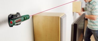
I believe that the project I want to talk about will be of interest to everyone involved in electronics. Namely, we are talking about a miniature laser engraver, with which you can apply images to cardboard, wood, vinyl stickers and other similar materials. I got the idea for the project from this tutorial, doing something my own way. Laser engraver in action and device assembly process
Materials and tools
To create an engraver you will need the following basic components:
- Arduino UNO (with USB cable).
- 2 stepper motors from DVD drives.
- 2 controllers for A4988 stepper motors and a corresponding expansion board for Arduino.
- 250 mW laser with tunable optics.
- Power supply (minimum - 12V, 2A).
- 1 N-channel field-effect transistor IRFZ44N.
Here is a list of required tools:
- Soldering iron.
- Drill.
- Metal file.
- Sandpaper.
- Wire cutters.
- Glue gun.
ZHILTSOV DMITRY
INTRODUCTION
In the previous article I described the experience of assembling and setting up an engraver from a Chinese kit.
After working with the device, I realized that it would not be out of place in my laboratory. The task has been set, I will solve it. There are two solutions on the horizon - ordering a kit in China and developing your own design.
DESIGN DISADVANTAGES WITH ALIEXPRESS
As I wrote in the previous article, the set turned out to be quite functional. The practice of working with the machine revealed the following design flaws:
- The design of the carriage is poorly designed. This is clearly visible in the video in the previous article.
- The rollers of the moving units are mounted on the panels with M5 screws and are connected to the panel on one side only. At the same time, no matter how you tighten the screws, there remains some play.
PLASTIC PARTS
Since the frame made from a machine-made profile is quite decent, it was possible to eliminate the identified shortcomings by recycling the plastic parts.
I described the laser holder quite well in a previous article. I also added an additional piece to the design that connects all four rollers on the right and left panels. This detail made it possible to eliminate play when moving panels.
All parts have fairly simple shapes and do not require supports or other difficulties when printing.
The set of plastic parts in the online store is slightly different from those presented in the article - modernized parts are presented. The bushings for the rollers have been strengthened and nut stops have been added.
Models of plastic parts from the article are available for printing:
https://www.thingiverse.com/thing:2703455
DEMONSTRATION OF WORK
The engraver's work and appearance can be assessed in the following video.
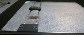
ENGRAVER CONSTRUCTION
The frame of the engraver is built on a machine-made aluminum profile 20x40. The parts supporting the moving parts of the engraver are made on a 3D printer. The moving parts move on standard rollers. The carriage carrying the laser module allows you to adjust the height of the laser above the desktop, which allows you to focus the power of the laser beam in a fairly large range.
The assembly of the structure is shown in 3D PDF format.
ASSEMBLY
The design is very simple. For this reason, assembly will not take much time and pain if you follow the recommended assembly sequence.
STEP 1. FRAMEWORK
As described above, the frame is constructed from 20x40 structural profile. To twist the profile together, internal corners are used.
On longer parts, threads are cut in the central holes of the ends for mounting legs and side panels (on the middle length).
The frame is twisted at the corners, with short parts inward. At this stage, you should not fully tighten the screws - it is better to do this after installing the legs.
The legs are attached with screws at four points. This is done so that the frame is assembled without possible distortions.
First you need to secure all four legs, again without fully tightening the fasteners.
Now you need to find the most flat surface possible! Arrange all the parts so that the frame “stands” tightly, without playing on the surface.
We stretch all the fasteners, starting from the inner corners and controlling possible distortions with a square.
STEP 2. RIGHT PANEL
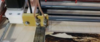
Before assembling the right panel, a flexible coupling must be installed on the motor shaft.
Then you need to screw the stepper motor through a plastic spacer.
The position of the cable outlet and the spacer are clearly visible in the figure below.
STEP 3. LEFT PANEL
To assemble the left panel, you only need to press the bearing into the hole.
I tried to eliminate the gluing operation. To do this, he “sent a wave” along the surface of the hole for installing the bearing. For this reason, it is necessary to press the bearing firmly.
STEP 4. INSTALLATION OF THE LEFT PANEL
The following parts are required for installation.
First you need to install the top rollers.
Then install the assembly on the profile.
And secure the lower rollers. The figure clearly shows that the mounting holes of the screws for fastening the rollers have a stroke of several millimeters. This is done so that the upper and lower rollers can be tightly tightened on the profile, eliminating play. The only thing is that you need to act carefully and not overtighten. In this case, the stepper motor will require excessive force to move the panels.
STEP 5. INSTALLING THE RIGHT PANEL
The following parts are required for installation.
First you need to install the top rollers.
Then install the assembly on the profile and install the lower rollers. Further installation is identical to the installation of the left panel.
After tightening the screws, you will need to check the progress of the panel. It should move quite easily and there should be no play.
STEP 6. INSTALLING THE GUIDE CARRIAGE
This design uses both panels to transmit movement along the Y axis. In order not to use 2 stepper motors, torque is transmitted to the left panel through a shaft with a diameter of 5 mm. After preparing the details, we begin.
First, the coupling shaft is installed and clamped with the flexible coupling locking screws.
During installation, it is necessary to ensure that the pulleys are not forgotten. There is no need to rigidly fasten them at the moment. Adjustment will be required when tightening the belts.
STEP 7. CARRIAGE
The carriage assembly is discussed in detail in the previous article...
Assembly is not particularly difficult.
STEP 8. INSTALLING THE CARRIAGE ON THE RAIL
First you need to collect all the necessary parts.
All installation operations are identical to the panel installation operations.
STEP 9. INSTALLATION OF BELTS
The belts are tightened with screws under the profile nuts. You will need to cut 3 straps in place and prepare the fasteners.
To begin with, the edge of the belt is located in the profile niche with the tooth down. After this, the nut is installed. It will take some force to install the nut.
When tensioning the belt, you will need to set the position of the pulley. The pulley is positioned so that throughout the entire run the belt rubs against the side edges of the pulley as little as possible.
To install the guide carriage belt, it is better to lift it as shown in the figure below, since it is still better to install the nuts into the niche from the end.
Afterwards the guide is lowered to its normal place.
Before tightening the second “tail” of the belt, you must make sure that the belt is tensioned sufficiently.
This completes the assembly of mechanics.
CONTROLLER
I plan to prepare a description of the controllers for controlling the engraver in a separate article. Follow the publications!
ASSEMBLY KIT AND TURNKEY LASER ENGRAVER
From December 2022, sets of parts for the laser engraver described in the article are available in the online store. Information is available in the online store.
YOUR SUPPORT WILL HELP YOU WORK MORE ACTIVELY ON THE BLOG, PUBLISH MORE ARTICLES, WHICH IN TURN WILL HELP YOU IMPLEMENT INTERESTING PROJECTS.
THANK YOU FOR PARTICIPATING IN THE LIFE OF THE BLOG!
| YANDEX | WEBMONEY | QIWI | PAYPAL |
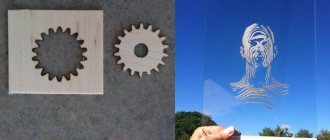
Features of using contours
If you have already figured out the question of how to make a hand-held laser engraver, then it is necessary to clarify the question of the parameters of the contours that can be applied using such a device. Such contours, the inside of which is not filled even if the original drawing is painted over, must be transmitted to the engraver’s controller as files not in pixel (jpeg), but in vector format. This means that the image or inscription applied to the surface of the processed product using such an engraver will not consist of pixels, but of dots. Such images and inscriptions can be scaled as desired, focusing on the surface area on which they should be applied.
Using a laser engraver, almost any design and inscription can be applied to the surface of the workpiece, but to do this, their computer layouts must be converted into vector format. This procedure is not difficult to perform: special programs Inkscape or Adobe Illustrator are used for this. A file that has already been converted to vector format must be converted again so that it can be correctly processed by the engraving machine controller. For this conversion, the Inkscape Laserengraver program is used.
» data-lazy-type=»iframe» src=»data:image/gif;base64,R0lGODlhAQABAIAAAAAAAP///yH5BAEAAAAALAAAAAABAAEAAAIBRAA7″>
Scope of application of milling and engraving machines
Milling and engraving machines are used to create products in everyday life and business. This:
- creation of three-dimensional logos, emblems, letters;
- production of souvenirs - icons, paintings, bas-reliefs made of wood and plastics;
- creation of elements of board games and 3D construction sets (prefabricated models);
- production of cliches, stamps for printing houses;
- jewelry products - engraving, making models for precision casting, creating products from semi-precious stones (gems);
- production of kitchen utensils and decorative elements;
- creating molds for chocolate confectionery;
- production of toppers (advertising signs for organizing holidays, anniversaries, weddings).
Laser for metal engraving and how the device works
It makes no sense to describe in words how to make a laser engraver with your own hands from a 3D printer or based on Arduino Uno. It will be much more informative to see everything with your own eyes. We invite you to see how to make a similar CNC laser engraver.
In fact, you can even engrave a photo on such a laser machine by launching the desired program. Many people ask how to prepare a photo for laser engraving. It's simple - the photo is scanned and then loaded into the program.
PHOTO: bing.com Engraving a photo on metal
Software installation
Your laser grower, which must operate in automatic mode, will require not only installation, but also configuration of special software. The most important element of such support is a program that allows you to create the contours of the desired design and convert them into an extension that is understandable to the control elements of the laser engraver. This program is freely available and can be downloaded to your computer without any problems.
The program downloaded to the computer controlling the engraving device is unpacked from the archive and installed. In addition, you will need a library of contours, as well as a program that will send data on the created drawing or inscription to the Arduino controller. Such a library (as well as a program for transferring data to the controller) can also be found in the public domain. In order for your laser homemade product to work correctly, and for the engraving performed with its help to be of high quality, you will need to configure the controller itself to the parameters of the engraving device.
Tabletop
The basic configuration usually comes with a lamella tabletop, with a wide arrangement of lamellas; such a table is good for large-figure cutting; the ribs of the lamellas rarely touch the material and leave minimal soot on the back side of the material at the places of through cutting. The ends of each lamella can be adjusted in height using adjusting screws and thereby set up a perfectly flat, or vice versa uneven - with differences due to the bends of the reverse side of the material, working surface:
The second type of table is a honeycomb table, it is used for working with small parts so that they do not fall between the lamellas, it is interchangeable with a lamella table - the frame with lamellas is removed and the frame with the honeycomb table is placed on the seat
The third table, the installation of which must be provided at the factory, is a lifting table. Such a table is needed for working with thick materials; it is usually needed by all engraving machines, because... The product for engraving can be of any unpredictable thickness. This table is also necessary for using a rotating device; the rotating device has its own height of up to 20 cm, and the platform under it must be lowered below the working plane. There is a nuance that different manufacturers implement the lifting table platform differently, so in Alfa-J the lamella and honeycomb tabletop are integrated into the lifting table, and they rise and fall, which is logical, together with the table
However, the manufacturer JQ does not believe that the lamella and honeycomb tables should rise and fall together with the lifting table, so the frames of the tables are fixed motionless, and the blind platform of the lifting table rises and falls, thus the lifting table becomes a full-fledged independent third table for working with a rotary device This solution seems more convenient:
What do you need to consider when creating a homemade engraver?
When manufacturing and operating any laser equipment, it is important to consider that the radiation is dangerous to humans. When setting up and testing lasers, there is a risk of burns and visual impairment. This indicates the need to comply with safety measures. First of all, you need tinted glasses to protect your eyes. In general, assembling an engraver yourself is not much different from installing other systems with elements of optics and electronics.
Mechanics
The mechanics of a laser engraver are the most important element to ensure positioning accuracy, speed and durability. Despite the importance of choosing high-quality mechanical components, when choosing a laser engraver, many customers are chasing a low price and make the mistake of purchasing the cheapest = lowest-quality equipment.
The very first thing you should pay attention to is the choice of guides. In industrial laser machines, it is permissible to use ONLY linear rail guides!
The use of circulating balls in a linear bearing provides a large contact area with a hardened rail: minimal resistance, high load capacity, rigidity, accuracy, the ability to operate at high speeds, ease of installation and maintenance, maintainability - all this is applicable to linear rail guides and not applicable to cylindrical ones guides, which are sometimes found in the segment of the cheapest laser machines.
Among the manufacturers of rail linear guides, in order of decreasing prevalence and maintainability, the following are recommended:
- HIWIN
- THK
- PMI
To maintain rail guides, it is enough to wash the rail and slider bearing with a degreaser and fill the slider with new thick grease, and if the guide balls in the slider are completely worn out, replace the slider, which costs no more than 5 thousand rubles.
If the cylindrical linear guide jams, the entire guide will need to be replaced, and this will cost a fortune. Avoid these cylindrical guides:
Another unsuccessful design solution is a beam with rollers, when the beam also serves as a guide:
In practice, plastic rollers and the beam wear out in 3-6 months, the rollers wear off, and the beam develops a groove and gouges in which the rollers begin to get stuck, as a result, work without defects is impossible, the beam and rollers are subject to replacement, but they are difficult to find, since suppliers of equipment of such a low class rarely care about the supply and availability of spare parts, beams with rollers are not compatible from different machines, so it is not a fact that what is found or ordered from China will fit - this will lead to machine downtime and loss of orders, and possibly the machine will prove to be unrepairable at all.
Air pump
The air pump serves to remove combustion products from the optics in the laser head, as well as to remove combustion products from the cutting area. To suit the customer's needs, it is possible to equip up to an air pump for a laser engraver 385 W 300L/min. Such a powerful pump may be required to cut paper and cardboard without burning, or to cut wood with minimal carbon deposits.
Cooling system (chiller)
The cooling system is selected for the laser emitter and operating conditions.
The simplest and cheapest cooling will be provided by a water pump; this device has neither a water flow sensor nor a temperature sensor; using a water pump to cool a laser emitter is quite dangerous, since it will not report overheating, will not stop the emitter if it fails, and will not will cool the water below the room temperature, although the recommended emitter temperature is not higher than 18°C. We do not recommend using water pumps and do not use them even in the starter kit, which competitors take advantage of and lower the price of machines by equipping them with simple water pumps.
A little more expensive and more functional - air-cooled chillers, type CW-3000, they still cannot cool the coolant below the room temperature, since they work on the principle of heat exchange with the environment - fans blow air from the room onto the radiator with water flowing through it, but are already equipped with a water flow sensor - they will stop the emitter in case of pump failure, equipped with a temperature sensor and signal and stop the emitter in case of overheating.
Perfect double-circuit chillers with a closed freon circuit are mini refrigerators that will cool the water below the room temperature, therefore they will be suitable for working in hot weather and will keep the temperature below the recommended 18°C, with them you can operate the emitter even around the clock, if, of course, you choose the right one such a chiller for the power of the emitter. Freon chillers are series CW-5000 and older. But there is one nuance in the choice, in that the CW-5200 series chillers have a cooling capacity TWO times higher than the CW-5000 series chillers, and cost only 10% more. Therefore, we recommend equipping laser machines with chillers of the CW-5200 series.