How much oxygen is consumed during welding?
Oxygen allows you to bring the flame temperature to the desired temperature during welding. Gas-flame processing allows you to obtain high efficiency of work and a good final result. During the work, gaseous oxygen is used.
Oxygen allows you to bring the flame temperature to the desired temperature during welding. Gas-flame processing allows you to obtain high efficiency of work and a good final result. During the work, gaseous oxygen is used.
The level of gas consumption will depend on a number of parameters, including the thickness of the wire and metal, as well as the type of seam. Below we provide a table of gas consumption when using the most common mixture with acetylene.
Metal thickness, mm
To find out more details, contact. Our specialists will answer questions about the consumption of a particular gas, as well as the features of its use in various conditions. We will supply you with the type of cylinder you need at the best prices.
source
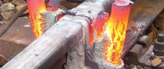
How metal is cut with gas
The most common method for cutting metal today is autogenous, also called gas or oxygen. Its essence boils down to the fact that under the influence of a gas flame, the metal heats up and begins to melt, and under the influence of a stream of oxygen it burns, making a narrow groove.
Acetylene, propane-butane, natural and coke oven gas are used as a heater.
Surface gas cutting is used in cases where it is necessary to remove layers of metal to form splines, grooves and other structural elements.
The dividing type involves making a through cut to obtain the required number of metal elements and parts. Burning through metal to create deep or through holes is called spearing.
Table of cutting thicknesses and gas consumption for NX type mouthpiecesThis results in a cut. Oxygen is supplied under high pressure, often reaching 12 atmospheres; such a jet, even without fire, can cut the skin.
The structure of the cutting apparatus is designed as follows:
- gas-burner;
- two cylinders;
- mixer;
- pressure regulator;
- hoses.
A gas burner consists of a head with several nozzles, usually three are enough. A flammable substance is supplied through two side ones, and oxygen is supplied through the third, which is located in the middle. The cylinders are designed directly for gas and oxygen; depending on the volume of intended work, cylinders of appropriate capacity are selected.
Gas-burner
To ensure one hour of continuous operation, an average of 0.7 m3 of acetylene (1 m3 of propane) and 10 m3 of oxygen will be consumed. In general, the required amount of feedstock will depend on the density of the metal and the required temperature to heat it. Propane consumption can be reduced by using special nozzle attachments that fix the gas supply in a certain direction; the closer the supply is to the oxygen stream, the higher the fuel consumption.
Hoses are necessary for supplying oxygen and flammable substances from cylinders to the mixer; they are also called hoses. The material from which the hoses are made is two-layer rubber, between the layers there is a frame made of cotton thread. Diameter – up to 12 mm, possibility of operation at air temperatures not lower than -35 °C.
A pressure regulator is necessary to provide different cutting modes and speeds. By supplying less fuel, it is possible to ensure the low temperature required for thin steel or low-strength metal, and also reduce the consumption of raw materials.
Another important function of the reducer is to maintain a uniform pressure level. If the gas supply is interrupted during the cutting process, the metal will quickly cool and further processing will become impossible.
Metal cutting with propane and oxygen
Necessary equipment
Cutter P101
The very first cutter was the P1-01 device, it was designed back in the USSR, then more modernized models appeared - P2 and P3. The devices differ in the size of the nozzles and the power of the gearbox. More modern manual settings:
- Change;
- Quicky;
- Orbit;
- Secator.
They differ in their range of additional functions and performance.
Quicky-E can carry out shape cutting according to specified drawings, the operating speed reaches 1000 mm per minute, the maximum permissible metal thickness is up to 100 mm. The device has a set of removable nozzles to ensure processing of metal sheets or pipes of various thicknesses.
Autogenous cutting machine Messer
This device can operate using various types of flammable gas, unlike the prototype P1-01, which runs only on acetylene.
The Secator manual cutter has improved characteristics compared to its analogues.
Cutter R2-01
With its help, you can process metal up to 300 mm thick, this is provided by additional attachments included in the kit, they are removable and can be purchased additionally as they wear out. Secator can produce the following types of cutting:
- curly;
- straight;
- ring;
- under the bevel.
The speed can be adjusted in the range from 100 to 1200 mm per minute, and the built-in freewheel ensures smooth movement of the machine along the sheet metal. The air-cooled gearbox ensures cleaner operation and reduces fuel consumption.
The above models are manual, that is, they are compact and controlled by the hands of a master. But for large volumes of processed metal, working with such
Stationary cutting unit
installations are inconvenient and ineffective. For industrial production, stationary cutting installations are used - this is essentially the same technology.
They are a machine with a table top into which a cutting mechanism is built. Its operation is ensured by electric
a compressor that requires an electrical network with at least 380 V and three-phase sockets. The technology of operation of models of stationary cutting units is in no way different from manual ones. The only difference is in productivity, maximum heating temperature, and the ability to process metal with a thickness of more than 300 mm.
Conditions for cutting metal with gas
Gas cutting of metal will be effective only when the ignition temperature of the metal is lower than the melting point. Such proportions are observed in low-carbon alloys; they melt at 1500 °C, and the ignition process occurs at 1300 °C.
For high-quality operation of the installation, it is necessary to ensure a constant supply of gas, since oxygen requires a constant amount of heat, which is maintained mainly (70%) by the combustion of metal and only 30% is provided by the gas flame.
If it is stopped, the metal will stop producing heat and oxygen will not be able to perform its functions.
Cutter operation, metal cutting training
The maximum temperature of hand-held gas cutters reaches 1300 °C, this is a sufficient value for processing most types of metal, however, there are those that begin to melt at particularly high temperatures, for example, aluminum oxide - 2050 °C (this is almost three times more than the melting point of pure aluminum), steel containing chromium – 2000 °C, nickel – 1985 °C.
If the metal is not sufficiently heated and the melting process has not begun, oxygen will not be able to displace refractory oxides. The opposite of this situation is when the metal has a low melting point and, under the influence of burning gas, it can simply melt, so this cutting method cannot be used for cast iron.
Safety precautions
It is better to entrust metal cutting using a gas installation to an experienced specialist, since if handled carelessly, the consequences can be quite tragic.
Safety precautions presuppose the following conditions:
Gas burner device
- good ventilation in the room where the work will be carried out;
- there should be no gas cylinders or other flammable substances within a distance of 5 meters;
- work must be carried out wearing a protective mask or special glasses, as well as fire-resistant clothing;
- the flame must be directed in the opposite direction from the gas source;
- During operation of the device, hoses must not be bent, stepped on, or pinched with feet;
- If you take a break, you should completely extinguish the flame at the burner and tighten the gas valves of the cylinders.
Compliance with these simple conditions will ensure safe and efficient work when cutting metal with a gas installation.
: Cutter operation, metal cutting training
Source: https://promtu.ru/obrabotka-metallov/gazovyiy-rezak-dlya-metalla
Limits of applicability
Thickness of materials being welded: the use of gas welding is economically feasible for materials up to 10 mm thick.
Types of materials: unalloyed and alloyed steels, cast steel, gray cast iron, non-ferrous metals.
Area of use: welding of thin-walled metal products, agricultural and transport engineering, installation and repair of pipelines.
Parameters: melting rate of steel 0.2 - 0.5, aluminum 0.15 - 0.2 kg/h.
Selection of flame characteristics: neutral flame (combustible gas: oxygen ratio = 1:1) is used when welding steel, oxidizing flame (excess oxygen) when welding brass, reducing flame (excess flammable gas) when welding aluminum and aluminum alloys.
Seam position during welding: bottom, horizontal, horizontal on a vertical surface, semi-ceiling, ceiling, vertical (bottom up and top down).
Consumption of welding materials
Combustible gas consumption: with a material thickness s = 1 mm, 100 acetylene (300 liters of acetylene are obtained from 1 kg of calcium carbide; 10 liters of water are required for complete decomposition of 1 kg of calcium carbide).
Welding wire consumption for gas welding depending on the thickness of the metal (when cutting edges with an opening angle of 50°)
The maximum permissible gas withdrawal from a cylinder is: acetylene 1000, oxygen 10,000 from each cylinder.
Operating pressures recorded by the gearbox pressure gauge: for acetylene 0.2, for oxygen 2.5 - 3.5 kg/cm².
Combustible gases for gas welding
| Parameter | Acetylene C2H2 | Domestic gas | Hydrogen H2 | Propane C3H8 |
| Flame power, kcal/(cm². s) Flame temperature when using oxygen, °C | 10,7 | 3,03 | 3,34 | 2,56 |
| 3200 | 2000 | 2100 | 2750 | |
| Ignition concentration, % (volume) | 2,8 — 82 | 6,5 — 35 | 4,1 — 75 | 2,1 — 9,5 |
| 2,8 — 93 | 4,5 — 95 | 3,0 — 45 | ||
| Minimum ignition temperature in oxygen, °C | 300 | 450 | 450 | 490 |
| 1,171 | 0,680 | 0,090 | 2,004 | |
| Storage conditions | In a steel cylinder under pressure up to 15 kg/cm² | Selection from the city network | In a steel cylinder under pressure up to 150 kg/cm² | In a steel cylinder |
| Cylinder marking color | Yellow | Red | Red |
Granulometry of carbide grains (according to TGL 11649, sheet I):
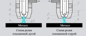
Cutting metal with an oxygen-propane cutter
If there is a need to work with thick-layer metal, a gas cutter is used. It cuts a metal sheet using a hot flame jet. It is formed by mixing two gases - propane and oxygen.
It is impossible to cut high-carbon metals, copper and its alloys, and aluminum with an oxygen-propane cutter. The range of materials that can be affected is limited to low-carbon steel grades from 08 to 20G according to GOST (1050-60) and medium-carbon steel - from 30 to 50G2 (GOST 1050-60).
A propane cutter cuts metal with a thickness of no more than 300 mm.
To work you must have
- high pressure oxygen hoses
- propane and oxygen cylinders
- mouthpiece
- cutter
All parts of gas equipment are standard and can be replaced if damaged.
Preparing for work
Before starting work, you need to make sure it is safe: there should be no traces of oil or other flammable substances on your clothes, floor, and surrounding surfaces. Next, you should inspect the gas equipment for completeness and serviceability. The following steps will help get your equipment ready:
- Flush all high pressure hoses with gas to remove dust and dirt before connecting them. Check for suction in the cutter channels. Attach the oxygen hose to the right-hand thread fitting using a nipple and nut. Attach the propane hose to the left fitting;
- Check for gas leaks in detachable connections;
- Check the serviceability of the pressure gauges. Pay attention to the tightness of gas reducers.
Beginning of work
Oxygen consumption when cutting metal is 10 times higher than propane consumption.
- Close all cutter valves and set the operating atmospheres on the gearboxes: oxygen - 5, gas - 0.5.
- Open the propane tank a quarter of the way and light it.
- Place the torch nozzle at an angle against a metal surface and slowly open the oxygen control.
- Proceed with the process of adjusting the flame: alternately open the oxygen and gas until the flame turns blue and has a crown.
- Select the flame strength based on the thickness of the metal.
Cutting process
- Start cutting the metal from the point where you want the cut to start.
- Heat this point to the ignition temperature of the metal (1000-1300 C). When the metal ignites (the surface will look wet), open the cutting oxygen valve and release a narrowly directed stream.
- Smoothly move the oxygen torch along the cutting line, at an angle of 84-85° in the opposite direction from the cut. If the metal thickness is more than 95 mm, make a deviation of 7-10°.
- After the cut line has reached 15-20 mm, change the inclination angle to 20-30°.
With the correct choice of the speed of movement of the cutting torch, a stream of sparks and slag flies out of the cut straight down, and the edges are clean and there are no smudges or deposits.
If your oxygen hose breaks during work, don’t panic. Close the propane supply and then both tanks. The flame that disappeared during the adjustment process must be re-ignited by first closing the cutter valves.
Safety precautions when cutting and welding
The developed clear safety rules made it possible to make the process controllable, the life and health of carvers and others became out of danger:
- Using a special mask with light filters, a respirator and a protective suit.
- Admission to work for persons who have reached the age of 18 and have completed a special course in gas work and have a certificate with a mark for carrying out this type of work.
- Cleaning the tightness of all connections of equipment, pipelines and fittings to prevent gas leaks.
- Use of special carts and stretchers to move individual cylinders. No cylinders hitting each other during transportation.
- Liquefied gas, grease, and oil must not come into contact with the oxygen reducer, valve or hose.
- Do not open the reducer or oxygen cylinder valve with oily hands.
- Before starting work, it is necessary to release the mixture of gas and air formed in the hose through the cutter. This way we prevent the occurrence of backlash into the hose and reducer.
- Heating metal only with liquefied gas without oxygen is strictly prohibited.
Source: https://svarkagid.ru/tehnologii/rezka-metalla-kislorodom-i-propanom.html
Auxiliary equipment for gas welding
Auxiliary equipment for gas welding
| Auxiliary equipment | Wednesday | Options | Manufacturer |
| Distribution rack I | Oxygen, nitrogen, compressed air, hydrogen, propane, acetylene, carbon dioxide | Distribution rack for 4 - 12 steel cylinders | Autogen |
| Distribution rack II | Distribution rack for 2x6, 2x8; 2×10, 2×12, 2×24 steel cylinders | ||
| Standard steel compressed gas cylinders | Oxygen, nitrogen, compressed air, acetylene, carbon dioxide | Volume 40 l, weight without gas 70 kg | |
| Trolley for shelving | Oxygen, nitrogen, hydrogen | Rack for 20, 33, 54, 72 steel cylinders | |
| Cylinder connection | Oxygen, hydrogen, propane, acetylene | — | |
| Transport trolley for cylinders: | |||
| execution type I | 2 steel cylinders | — | Enterprise, Gräfendorf, GDR |
| execution type II | 1 steel cylinder, 1 gas generator | — | |
| Quick acting valve, single gas | Oxygen, acetylene | Flow rate 5200 m³/h | Autogen |
| Quick acting valve, mixture of two gases | Mixtures: oxygen - acetylene, oxygen - household gas, oxygen - hydrogen | Oxygen consumption 5200, acetylene 2000 m³/h | |
What thread is on the cylinders?
Threads for valves in the necks of cylinders in accordance with GOST 9909-81 W19.2 - 10-liter and smaller volume cylinders for any gases, as well as carbon dioxide fire extinguishers W27.8 - 40-liter oxygen, carbon dioxide, argon, helium, as well as 5, 12 , 27 and 50 liters propane W30.3 - 40 liters acetylene M18x1.5 - fire extinguishers (Attention! Do not try to fill powder fire extinguishers with carbon dioxide or any compressed gas, but it is quite possible to fill propane.)
Thread on the valve for connecting a G1/2″ reducer - often found on 10-liter cylinders; for a standard reducer you need a G3/4″ adapter - standard on 40-liter oxygen, carbon dioxide, argon, helium, welding mixtures SP 21.8×1 /14″ - left thread for propane
Selection of base and filler materials, heat treatment
For the groups of materials specified in clause 1.1.1, the selection of base and filler materials when welding steels is made according to table. 1.7. Properties (chemical composition and strength parameters) are given in table. 1.8. The welding parameters of steel casting correspond to the welding parameters of steel. Welding of gray cast iron is carried out with preheating either up to 250 °C (“semi-hot welding”), or up to 600 °C (hot welding); heating and cooling speed 50°. Filler material - welding rod made of amanite (gray cast iron, Ó in = 30 kgf/mm2, hardness HB 200, melting point 1200 °C), with a diameter of 4, 5, 6, 8, 10, 12 mm (manufacturer - a welding equipment company , Eisenach). The most interesting (in terms of gas welding of non-ferrous metals) are primarily aluminum and its alloys. Filler materials can be selected according to TGL 14908, fluxes - according to TGL 14709, sheet 2, F-; preparation of connections - according to TGL 14906, sheets 1 - 5.
Welding, soldering, gluing and cutting materials
Surfacing
Surfacing is a type of welding that consists of local application of material by welding to the main product to protect it from corrosion and wear or to build up and increase its volume.
Laser welding
In laser welding, a light beam is used to melt the welded edges. The concentrated light beam is characterized by monochromaticity, coherence, parallelism and high energy density.
Electron beam welding
The welding process uses heat generated by the collision of accelerated electrons with the metal of the parts being welded.
source
Calculation of consumption rates for welding materials, page 2
The value of Kur is determined experimentally, by surfacing a bead on a plate, or by calculation using the formula:
where Kp is the coefficient of transition of the electrode metal into the weld, %;
The Kp value is indicated in the electrode passport.
The value of Cog is determined by the formula:
where Le is the total length of the electrode according to GOST 9466, mm;
lо – cinder length according to GOST 9466, mm.
The value of Kpokr is determined experimentally or calculated using the formula:
where q is the coating mass coefficient specified in the electrode passport, %.
The values of the coefficients Kur, Cog, K cover, Kp depend on the brand and diameter of the electrodes used and are given in /1/.
2.2 Semi-automatic welding in carbon dioxide environment
The standard consumption of welding wire for semi-automatic welding with a consumable electrode in a carbon dioxide environment is established based on the mass of deposited metal, technological losses and waste and is determined by formula (1). The amount of technological losses of welding wire should not exceed 15%.
The standard consumption of welding wire is assumed to be equal to the mass of the deposited metal with a loss coefficient Kpr=1.15. When welding short-length seams (l = 0.3 m), the Kpr coefficient should be taken equal to 1.3 per kg of deposited metal.
The standard carbon gas consumption during welding is set depending on the mass of the deposited metal and is determined by formula (1).
The carbon dioxide consumption coefficient Kg takes into account gas consumption for welding and is determined by hourly consumption and welding time, taking into account the inevitable technological losses of gas for purging the system, leakage due to loose connections of hoses and residue in the cylinder (tank), as well as gas consumption for all types of tack work.
Depending on the conditions of welding, based on experimental production data from plants, the value of the carbon dioxide consumption coefficient Kg per 1 kg of deposited metal is set as follows:
— when welding in enclosed spaces (shops), where there is no strong air exchange, Kg = 1.6 kg;
— when welding in open areas; where there are unfavorable atmospheric conditions (strong wind, severe frosts, etc.), Kg = 3.0-4.0 kg;
- when welding short-length seams (l=0.3m) and intermittent ones Kg=2.0kg.
2.3 Semi-automatic and automatic submerged arc welding
The standard consumption of welding wire is determined based on the mass of deposited metal and technological losses and is determined by formula (1).
The sum of all technological losses of the welding wire is 3% of the mass of the deposited metal, therefore, the loss coefficient Kpr is equal to 1.03.
Flux consumption standards include flux consumption for the formation of a slag crust and its technological losses due to scattering and spraying during the welding process and when replacing used flux with a new one.
Flux consumption standards are determined by formula (1).
The flux consumption coefficient Kf (depending on the welding method and the thickness of the metal being welded) is given in Table 3
For electroslag welding of structures, the consumption coefficients of welding wire and flux per 1 kg of deposited metal are accepted as follows:
source
Welding methods
There are two types of welding: “pull” and “pull”. In the first case, the torch moves first, heating the weld pool to the required temperature, followed by the filler wire. In this case, it is necessary that the burner flame is supplied to the welding zone at an angle of 45°. The torch should move in circles or semicircles along the seam, the additive should keep up with the flame and move into the weld zone.
In the second case, on the contrary, the filler rod moves in front of the burner. Typically, thick metal workpieces are welded in this way. Because the process of melting the base metal and the additive occurs simultaneously, and the mixed molten metal completely fills the weld pool. But the most important thing with this method of joining is to achieve uniform mixing of the two metals. If the mutual penetration is weak, then the seam will turn out to be of poor quality.
By the way, the interpenetration of metals, scientifically called penetration, may look purely outwardly ugly, but at the same time the strength of the connecting seam will be as high as possible. And, conversely, a beautiful seam does not ensure a high quality welded joint. In this case, beauty can be deceiving. But in order for the result to be guaranteed to be of high quality, it is necessary to set the gap between the workpieces to a minimum, as well as carry out preliminary tacking for the same purpose - reducing the gap.