To transport electrical energy over a considerable distance and reduce technical losses, high-voltage power transformers (PTs) are used. They work on the principle of transformation, converting the electrical energy of 1 parameter into another dimension through electromagnetic induction. For this purpose, the electrical energy received from the brush device of the generators through the buses is supplied to transformers for upgrading and further transmission.
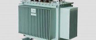
Power transformer 500 MVA
Design
Power transformers are made oil-dry. A high-voltage apparatus is complex engineering equipment.
The device includes:
- Installation stand.
- Rectangular oil tank.
- Thermosyphon filter.
- Magnetic cores.
- Low potential windings (2-layer cylindrical).
- High amplitude windings.
- Input bushings of 2 amplitude classes.
- Expansion tank.
- Gas relay.
- On-load tap-changer.
- Motor drive.
- Radiators with fans, coolers.
- Switching device drive.
- Shut-off valves for oil, water, gas.
Depending on the number of phases, transformers are produced: single-phase, three-phase.
Insulation
The windings of the power transformer are isolated from other windings and grounded parts.
Such insulation is called main, in addition to which there is also longitudinal, which is the insulation between the individual components of the winding structure - turns, layers, coils, and so on. It is carried out during the manufacturing process. The main one is installed during assembly.
The windings are insulated from the upper and lower yokes using oil channels and barriers that are formed by the yoke insulation, which covers the surface of the yoke, which faces the windings. When it is carried out, a barrier with attached gaskets made of pressed electrical cardboard creates the necessary oil gaps.
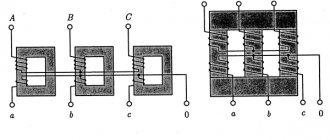
Principle of operation
The work of the ST is carried out according to the laws of electrical engineering. CT is no different from an ordinary transformer. The current passing in the primary winding changes in the time range by harmonics. It creates a powerful flow of magnetic fields in magnetic circuits. Induction penetrates the turns of the secondary winding, creating an electromotive force.
Transformer operating principle
The loads are removed from the bushings of the secondary winding on the roof of the transformer. The current parameters of the secondary winding are kept no higher than the calculated value. In this state, power plants operate for months, for a long time. 1 amplitude potential of low potential (6 - 10 kV) electricity is converted into a high amplitude class (35, 110, 220, 500, 1100 kV).
In operating mode, the ST is connected by switchgear buses and a power transmission line to the load of energy consumers. Without power take-off, the frequency of the electric current increases. STs working in a group are unloaded, close to idling operating modes. When power is taken from consumers, the frequency of the electric current decreases, the transformer is loaded at 100–140% power. When the frequency stabilizes at 50 + (0.5-1%), the power plants are transferred to a stable nominal operating mode. During the testing period, it is switched on briefly for short circuit modes. 99.99% of the electrical characteristics of the unit are checked, and its operating modes are adjusted.
Also read: Single-phase oil transformer - OMP
Short circuit mode
Transformers can be step-up and step-down, to determine this you need to find out the transformation ratio , with its help you can find out which transformer. If the coefficient is less than 1, then the transformer is step-up (this can also be determined by the values; if there is more in the secondary winding than in the primary, then it is step-up), and vice versa, if K>1, then it is step-down (if there are fewer turns in the primary winding than in the secondary).
Formula for calculating the transformation ratio
Where:
- U1 and U2 – HV and LV voltage,
- N1 and N2 – number of turns in the primary and secondary windings,
- I1 and I2 – current in the primary and secondary windings.
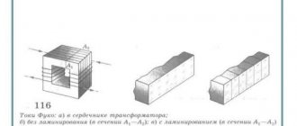
Theory
Electric current as an electromotive force <e.
d.
c.>, is possible only in the presence of an alternating (changing) magnetic field (the rate of change of the magnetic field is determined by the frequency of the supply current). In the simplest alternating current electric generator, where the field armature has a row (around the circumference) of permanent magnets with alternating polarity. Therefore, the number of magnets on the armature is always even; to excite the windings, the magnetic field is removed at least at two points, necessarily at different poles of the armature.
Main purpose
Industrial ST is produced at large electrical plants in the country. The industry produces installations with a capacity of over 1 million kVA. The amplitude of industrial voltage classes reaches 1.15 - 1.5 megavolts. ST from TPP generators removes current with an amplitude of up to 24 kV from brush devices. A further increase in amplitude occurs in ST up to classes: 110 – 1150 kV. Throughout Russia, power lines operate with an amplitude of 10 – 1050 kV. The current is supplied to consumers via overhead lines by step-down devices with an amplitude of: 0.4 -10 kV for industrial purposes, 220 - 380 V in the housing and communal services sector, to the population of apartment buildings, private sectors.
Electricity transmission scheme
In substation networks, multiple cycles of electricity transformation occur. It is changed regularly with powerful ST. Their potential, amplitude is 30 times higher, taken from the brush apparatus of generators of thermal power plants, hydroelectric power stations, nuclear power plants, and wind farms. Industrial CT maintains a constant current frequency of 50 (+/- 1%) Hz. The deviation limit according to the PUE is kept at 1% due to the failure of all consumer installations. CT for industrial use is made in 3-phase version. For a 1-phase network, 1-phase devices are produced.
Multilayer cylindrical bobbin windings
Multilayer cylindrical coil windings (Figure 3) are wound from round wire and consist of multilayer disk coils located along the rod.
Radial channels for cooling can be left between the coils (through each coil or through two or three coils). Such windings are used on the higher voltage side at Sst≤ 335 kV×A, Ist≤ 45 A and Ul. n≤ 35 kV.
Figure 4. Double-layer cylindrical winding Figure 5. Helical winding
Explanation of markings
Explanation of the markings, to enlarge the diagram, click on it
To enlarge the table, click on it
According to the number and connection diagram of the winding
STs consist of 2 or several windings. They are inductively coupled inside the apparatus. The power windings transmitting electrical power to consumers are called secondary windings. A multiphase type power plant is connected by windings into a star with many rays. 3-phase transformers are connected using a 3-beam star-delta circuit.
Types of windings and their features
A single-layer or multilayer cylindrical winding is formed by winding one or several layers of wire with a round or rectangular cross-section. The simplest is a single-layer winding of rectangular wire. The winding layer consists of turns wound along a helical line onto a paper-bakelite cylinder.
Each turn in the layer is laid close to the previous one in the axial direction of the winding. The turns of a cylindrical winding consist of one or more parallel wires located side by side and having the same position relative to the leakage field of the transformer. Typically, a winding of rectangular wire is wound flat, but if necessary, it can also be wound on an edge.
A helical or spiral winding consists of turns that are wound along a helical line with channels located between them. For example, the primary winding of a power transformer for powering radio circuits will have 1200 turns. Each such turn consists of either one (in rare cases) wire, or several identical wires of rectangular cross-section.
The second option is more common. In this case, identical wires are placed flat to each other in the radial direction. Such a winding can be single-pass or multi-pass.
Take into account the resistance of the power transformer windings, at which operation is highly not recommended.
How to choose
Indicators characteristic of ST for the construction and installation of thermal power plants, hydroelectric power plants, nuclear power plants, diesel power plants are: power, reliability of electrical supply. For certain categories of electricity consumers, an important factor is the reliability of power supply. When selecting devices, attention is paid to power line protection. High degree of financial efficiency of ST – design of an optimal network of distribution devices: outdoor switchgear, indoor switchgear, ASU for electricity transmission.
The costs of purchasing and servicing transformers include electricity conversion devices. The company is developing for the future and reconstructing production. The requirements for the technical equipment of electrical networks and the characteristics of power transformers are changing.
Ensuring uninterrupted power supply to the enterprise is done by installing a second power supply. The first one is constantly at work. The 2nd is considered reserve. Periodically, 1 out of 2 devices is taken out for major, medium, current repairs, adjustments, and testing of networks and equipment. The enterprise installs 2 units with the condition that each unit operates with a power load factor of 0.7 of the nominal parameter. If 1 working device out of 2 fails, one device is constantly switched to standby mode. During operation, the following arise: malfunctions, problems with protection, disruptions in the operation of switchgear equipment and substation. 2, the operating unit becomes subject to a power overload of 1.4 times, i.e. the second transformer can only be overloaded by 40%.
Why is this necessary?
The transformer is used to increase or decrease the supplied electricity. Why do you need to convert current? The point is that, according to the Joule-Lenz law, the heat that a conductor releases when an electric current passes through it is released depending on the strength of the current. Moreover, this dependence is quadratic, since the current strength in the formula has a second degree.
In practice, this means that increasing the current by 2 times will lead to an increase in heat generation by 4 times. Everything would be fine, but no one has yet canceled the law of conservation of energy. Heating the conductor consumes electricity, which humanity struggles to obtain. The only way out is to increase the voltage to the maximum.
According to Ohm's law, a certain equality is always maintained: the product of current and resistance is equal to the voltage in the network. Let us assume that the resistance does not change, since it depends on the properties of the conductive material. Then the only way out will be to raise the voltage as much as possible in order to reduce the current in the network.
High-voltage lines were not invented for fun. The only goal of such a complex system with transformers is to reduce losses as much as possible.
Sources
- https://odinelectric.ru/equipment/chto-takoe-transformator
- https://ProFazu.ru/elektrosnabzhenie/elektroset/transformator-toka-printsip-raboty.html
- https://lightika.com/osveshhenie/ustroystvo-i-princip-raboty-transformatora.html
- https://www.kipiavp.ru/pribori/transformator.html
- https://www.techcult.ru/science/5124-princip-dejstviya-transformatora
- https://www.RusElectronic.com/ustrojstvo-transformatora/
- https://principraboty.ru/princip-raboty-silovogo-transformatora/
Transformer protection
The standard type of protection according to the PUE is installed:
- Zero sequence current protection against external ground faults, clause 3.2.63.
- Protection against currents caused by external short circuits, clause 3.2.64.
- Operational acceleration of protection against currents caused by external short circuits with a time delay of 0.5 seconds, clause 3.2.65 (AT substations, ST block generator).
- Gas protection of the additional transformer clause 3.2.71.
- Protection of the on-load tap-changer contact device with a pressure relay, a separate gas relay, clause 3.2.71.
- Differential current protection of low voltage side circuits (AT) clauses 3.2.70 – 3.2.71.
- Differential phase overload protection.
- From internal damage: level + oil pressure, winding temperature, steel core, presence of gases.
CT protection panel:
Screw windings
Helical windings (Figure 5) are wound from a number of parallel rectangular conductors (from 4 to 20), adjacent to each other in the radial direction. If there are a large number of parallel conductors, they can also be located in each turn in several layers in the axial direction, or the winding is made multi-pass, that is, the parallel conductors are divided into 2 - 4 groups and each group forms an independent helical stroke of the winding.
Figure 6. Schemes of partial transposition of parallel conductors
When several parallel conductors are located nearby in the radial direction, the current is distributed unevenly between them, which causes an increase in losses.
The reason for the uneven distribution of current is that such elementary turns, consisting of one parallel conductor, are coupled with magnetic fluxes of different values and different electromotive forces (emf) are induced in them.
This difference in flux linkage is due to magnetic leakage fluxes that pass through the space occupied by the windings. In other words, we can say that the reason for the increase in losses is eddy currents induced by the magnetic field in the winding conductors and causing the surface effect phenomenon. As a result, the active resistance of the winding increases.
To ensure a sufficiently uniform distribution of current between the conductors, it is necessary to transpose (rearrange) the parallel conductors forming a turn (Figure 6).
With complete transposition, each conductor occupies in the radial direction alternately all positions possible within one turn. Often only partial transposition of the conductors is performed. Transposition is carried out in several places along the height of the rod.
Low voltage windings are made with screw windings at Sst≥ 45 kVA×A, Ist≥ 300 A.
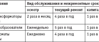
terms of Use
CT requires a high degree of reliability with high voltage and power values. This affects the quality of operation and prevention. Routine work is carried out for proper, complete maintenance, repair, testing, and adjustment. Transformers and equipment are located in the place where personnel are constantly on duty. Daily inspection schedules, control and measurement devices check the operating condition of the electrical network and transformers.
Monitor the readings of instrument sensors, measure:
- Temperature.
- Pressure.
- Oil level.
- Degree of desiccant depletion.
- Condition of oil regenerators.
Also read: Three-phase oil transformer - TMF
Checks for oil leaks in the transformer cage, outdoor switchgear, closed switchgear, mechanical damage in the housing, flange joints (oil, coolant), radiators, fans, pipe sections. The number of operating fans and the oil level in the gas analyzer are monitored at a certain transformer load. For each mode, its own number of operating equipment, parameters of the cooling medium, gas, water, oil are given. In devices with permanent staff duty, inspections are done less frequently: once every 30 days. At least once every ½ year, an inspection of outdoor switchgear, indoor switchgear, indoor switchgear, and transformer points is carried out.
According to the maintenance schedule, during maintenance, oil is added and unsuitable transformer oil is replaced with a new composition. The quality of the oil is determined by chemical laboratory analysis. The PUE, instructions for transformers and equipment provide criteria for oil requirements, visual inspection, and color. In emergency situations or sudden changes in outside air temperature, unscheduled inspections are carried out.
Protection is subject to verification. Once every 365 days for major repairs, the oil is taken for laboratory analysis. The frequency of maintenance of voltage regulation devices of power transformers is associated with checking the contacts of copper and brass for oxidability. They perform preventive maintenance, cleaning, lubrication, reassembly, and tightening with a torque wrench to reduce the transition resistance in the contact assembly.
In order to change the oxide film, 2 times every 365 days the transformers are disconnected from the electricity, their load is removed to 0, the switches are placed in various adjustable positions several times. Methods of changing positions are done during the transitional autumn-winter period until the maximum load is gained.
Requirements for switchgears: outdoor switchgear, indoor switchgear, indoor switchgear
The power line is connected from the input of a remote substation. Switchgears: outdoor switchgear, indoor switchgear, indoor switchgear are designed for the length of the line section. ST, VL in switchgear protect against overvoltage and short circuit currents. Voltage reduction systems are installed between the electricity generation switchgear and the consumer. Powerful installations are installed at 2 nodes: switchgear and electrical substation. They are engaged in the transformation of high-power electricity.
Industrial installations include powerful installations:
- Power transformers.
- Autotransformers.
Transporting electrical energy over long distances requires reducing losses in switchgear, equipment, and the main network. The electricity transformation method is used. Electric current is supplied from the generators to the station. The voltage increases to the amplitude of the power line.
You can also read the information in the book, from pages 55 to 76: Open the book for reading
Multilayer cylindrical windings
Multilayer cylindrical windings (Figure 2) are made of round or rectangular conductors, which are placed along the rod in several layers, with cable paper insulation laid between the layers.
With a large number of layers, the winding is divided into two concentric coils, between which a channel is left for cooling. These windings are used at a power per rod Sst ≤ 200 kVA×A, at a current per rod winding Ist ≤ 135 A and voltage Ul. n≤ 35 kV.