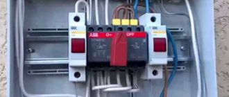
Incorrect generator connection diagram
Let's omit comments on the build quality of this shield. Why is such a scheme dangerous? When two machines are turned on simultaneously (in this case, “Input” and “External Rose and Generator” at the bottom left), we receive counter voltage on the generator line, which leads to its failure. A family member uninitiated in the scheme or the owner of the house who is thinking about the meaning of life can turn on two machines at once. It is necessary to use three-position reversing switches I-0-II (for example, ABB OT40F3C) It is strictly forbidden to connect one of the generator outputs to a common neutral bus unless the neutral is re-grounded in the main panel (CT circuit) and/or on a pole and/or in the metering cabinet . Such grounding, as a rule, is absent in old SNT or in villages where the norms for laying power lines are violated. By violating this rule, we transfer dangerous half-phase voltage from the output of our generator to the “public” neutral. This can lead to electrical injuries to your neighbors and electricians working on the line. How to determine if there is re-grounding? The neutral is grounded either at the top of the pole through the reinforcement terminal, or on a steel strip that runs along the pole and goes into the ground. One example of a circuit with grounding of the neutral on a pole and organization of grounding according to the TN-CS scheme
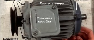
Grounding the neutral in the ASU
Scheme of Connecting a Generator to the Home Network
The number of phases that will be used in the generator depends on how many phases come from the main power supply.
Just one turn of the switch or operation in fully automatic mode and you will feel calm and safe. Generator autostart The most complete way to switch the load is using an automatic transfer switch.
Here it also makes sense to use partial automation, since semi-automatic machines are inexpensive. 220V home generator with autostart system from Kirill Plisov. It will be interesting to read:. The nuances are that when connecting a gas generator to the network, it is necessary not only not to confuse the phase-zero polarity, but also in some RCDs the power source is connected to the upper terminals, and the load to the lower ones.
Otherwise, you can get heavy fines for illegal tapping. At the location of the electrical panel.
Do not wear loose clothing, as the fan inside can pull in the fabric and other items of clothing. Connecting a single-phase generator to a three-phase network at home will not be a problem, the main thing is that the generator’s power is enough to consume the most important consumers in the house.
Preference should be given to a brushless design with better current characteristics and less radio interference. ATS circuit with two contactors and a phase control relay
Grounding
The very principle of operation of the generator involves the periodic occurrence of static electricity on its body, therefore all permanently installed devices necessarily require a separate grounding circuit.
The ideal option is to create a full-fledged grounding loop, but in general you can get by with the simplest method, for which you will need a metal rod 1.5-2 meters long, a steel bolt or clamp connection and a soft copper wire. A bolt is welded to the iron rod, and the pin itself is driven the entire length into the ground. The copper wire is screwed with one side to the bolt (or clamped with a clamp), and the other to the generator housing - the grounding is ready.
These are all the main ways to connect a gas generator to the network at home and possible nuances. The presented diagrams will help determine whether it is worth installing autostart systems or whether it will be easier to do with manual switching. Of course, when installing each individual generator, ATS unit or homemade autostart system, additional questions may arise, but they will have to be resolved in each case separately, depending on the device model and the home electrical circuit diagram.
How to connect a single-phase generator?
There are several connection options. The first is connecting the unit to a designated group of consumers.
Connecting voltage in manual mode
The second method is to use a rocker switch (switch) in 3 positions 1-0-2, in other words, in the 1st position, power is taken from the centralized (city) electrical network, switch position 0 - the electrical circuit is turned off, in position 2 - home connected to a backup source of electricity, in this option it is a gas, gasoline or diesel generator.
Without delving too deeply into the structure of the devices, we only note that the design of a changeover switch or a 3-position switch is quite simple and includes stationary contacts to which the wiring is connected (consumer-city-device generating electricity), and movable contacts that switch the consumer from the centralized power grid to the generator and back.
When switching a 3-phase load, the city-consumer will switch 3 phases, in other words, 3 city phases A-B-C go to the switch, and the same 3 phases go to the consumer.
When switching the consumer to the generator, we need to do it in such a way that all 3 phases receive electricity.
In this case, it is necessary to slightly modify the switch-switch - make a jumper between phases A-B-C on the side connecting the device that generates electricity. Now, when the consumer switches to the generator, electric current will flow to all 3 phases.
Connecting the consumer via contactors
The third way to connect a consumer to a single-phase generator is to use contactors. With this option, 2 contactors are used, one to power the consumer from a centralized network, the 2nd contactor is needed to connect the consumer to a backup source of electricity - a gas, gasoline or diesel generator. This method is acceptable when using automatic backup power (ABP).
When the consumer is powered from a centralized network, all 3 phases connected to the contactor go to the consumer. When connecting a generator, as in the version with a 3-position switch, at the contactor terminals in the area where the cable from the generator is connected, we need to slightly modify the switch switch - place a jumper between phases A-B-C.
When operating a single-phase generator, it is necessary to take into account that if there is 3-phase equipment, it must be disconnected from the power supply while the generator is operating, since this can cause breakdown of these devices.
Connecting three-phase models
Connection via an additional distribution machine. The circuit diagram for connecting the machines from the power line and the generator is almost the same, which makes it possible not to change anything in a functioning 3-phase electrical network. This approach to introducing an individual home into the network is considered the most reliable and ensures the efficient operation of the equipment connected to it.
To implement it, you will need to take certain actions.
- Turn off the 380 V input circuit breaker, stopping the supply of current to the house.
- Install a new 4-pole circuit breaker in the panel, the output terminals of which are connected by pieces of wire to the input terminals of all linear devices.
- The generator output cable with 4 wires (3 phases and neutral) is fed to the new circuit breaker, and each of them is connected to the correct terminal.
- If a residual current device is installed further in the diagram, when performing switching, the wiring of the wires connected to it (each of 3 phases and zero) is provided.
Connection via switch
A changeover switch (reversing switch) is the same switch, only with three positions.
When using it, the busbars from the generator are connected to one group of poles, and the supply wires from the power line are connected to another.
The central group of contacts of the switch, the wires from which go directly to the consumer, are sequentially transferred towards the input from the explosive or to the generator supply. In the middle position of the switch, the entire house is completely de-energized.
Using an electric motor
You probably know that the rotor of a conventional three-phase motor, after starting, continues to rotate after one phase is disconnected. It turns out that there is an EMF between the terminal of the disconnected winding and the activated terminals.
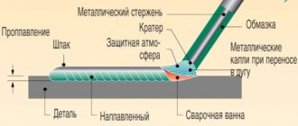
The phase shift between the stator windings depends only on their location. In a three-phase motor, these coils are located at an angle of 120º, which means they provide the same phase shift angle. This circumstance suggests that an asynchronous three-phase motor can be used to obtain 380 volts from a conventional single-phase network. A simple diagram for connecting an electric motor is shown in Figure 3. The capacitor in the diagram is needed only to start the engine. Once launched, you can disable it. We take the capacitor type MBGO, MBGP, MBGT or K42-4, the operating voltage of which must be at least 600 V. You can use the capacitor K42-19, with an operating voltage of at least 250 V.
How to connect a single-phase generator to a three-phase network.
How to connect a generator to the house ? It would seem that it could be simpler, start the generator, connect it to the house and that’s it, we live as before))). In previous articles, we have already looked at how to connect a generator to the house and the main mistakes that can lead to big troubles, the smallest of which is the failure of the generator.
In this article I would like to consider the issue of connecting a single-phase generator to the house
, in which all electrical wiring is designed and executed for a three-phase network. Oddly enough, many electricians, even with decent work experience, fall into a stupor and begin to reinvent the wheel))).
The most optimal solution when connecting a generator to the house
,
This is when, even at the stage of construction and electrical installation work, a separate group of the most critical consumers is provided for backup power supply. As a rule, some lighting, heating equipment, some sockets, and a security and fire alarm are connected to this group. This method is good because you can get by with a relatively low power generator.
But quite often, in 90% of cases, people only remember about purchasing and then connecting a generator to the electrical network at home when power outages begin.
In order for everyone to understand what goes where, we will try to explain everything in simple and understandable language, without the use of special terms and various abstruse language.
We do not recommend:
- Ground one of the generator outputs to the common house PE bus (ground). If your ground “falls off” (a wire rots or a connection comes loose), dangerous voltage will appear on all grounded appliances in your home.
- Connect budget generators directly to the load without using network interference filters. Changing the generator speed causes strong interference and voltage surges, which are dangerous for sensitive electronic equipment (automatic gas boilers, expensive household appliances).
- Use three-phase generators with a power of up to 10 kW for backup power at home. Phase imbalance will lead to rapid failure of the generator. Use single-phase generators with a phase combination circuit.
- Connect inverter generators to a common neutral bus. This can lead to rapid generator failure.
- Neglect the rule of grounding the generator housing itself.
- Use a non-inverter generator without a solidly grounded neutral of one of its outputs, because this leads to incorrect operation of differential protection devices (RCDs) and errors in the operation of phase-dependent boilers.
- Use the generator output for grounding, which is turned off by a single-pole circuit breaker on its body.
We’ll talk about how to properly connect a generator to the network (220/380V) of a country house later.
How to connect a gas generator
The use of an electricity generator in the house can be done in 2 ways: by connecting electrical appliances directly to the unit’s outlet through an extension cord and by integrating the generator into the general electrical network of the room. If the first method is suitable for infrequent and short-term use (for example, in the country or in nature), then the second method is used during long power outages or in the absence of electricity at the site. In this article we will talk about generators as the main or backup power source in a country house or in any other building (in a store, workshop, production facilities) and about their correct connection.
Before connecting the power plant to the home network, you need to solve several problems:
- Understand how much backup power is needed. Assess how critical a power outage will be or whether constant power is required (for example, if a server is running in the house or just expensive equipment)
- Determine the location for the unit, taking into account safe operation and close proximity to the connection point.
- Calculate the required power for all electrical appliances in the house that can be used. It is also necessary to take into account possible losses on the line and leave a small power reserve (20–30%).
- Decide whether to use automatic or manual control.
The use of automatic control and protection systems will be more expensive due to the cost and the need for additional measures to protect the wiring from strong voltage surges when switching from the general network to the generator and vice versa. A more gentle measure would be to use manual control when you make the switch yourself.
When connecting the generator, it works with 3 networks:
- the general network through which the house receives electricity;
- home internal network;
- generator wiring.
Why can't you connect the generator through an outlet?
Connecting via a connector is a fairly simple procedure, but you should not give it preference when connecting a generator to a general house electrical network, as this entails many problems:
- Possibility of overload at the connection point - since the entire load falls entirely on only one outlet, this is fraught with rapid overheating, melting and even fire.
- The absence of a separate circuit breaker in the power line that would be responsible for safety and emergency shutdown in the event of dangerous situations.
- Human inattention - when turning on the unit, sometimes they forget to turn off the input machine. This entails overload and activation of the protection unit
- Possibility of generator breakdown when starting electric current through the line and reaching the contacts of a working unit. In this case, major repairs or complete replacement of the power plant may be required.
Methods for connecting a generator to the network
There are 3 ways to properly connect a power plant to a home network.
Changeover (reversible) switch (manual control)
This is a device that will be responsible for a secure connection. Advantages of this type of control:
- Simplicity of design - the switch is equipped with 3 modes - 1-0-2. 1 — power from the general network, 0 — closure of all contacts, 2 — power from the generator.
- Simplicity of connection - the general network is connected to the upper part of the switch on the left side, and the generator on the right. At the bottom, jumper wires form the input to the common house line. For system security, it is recommended to add machines to each line. They ensure system shutdown during overloads and other critical situations.
- Affordable price - switches of this type cost around 500 rubles.
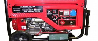
Selection of electric generator
A home power plant consists of an internal combustion engine and a rotating generator that produces electricity. The most common are four-stroke models with a maximum speed of 3 thousand revolutions. The volume of the fuel tank in domestic models is 10-15 liters. The main selection criterion should be the area of use. Generators can act as the main source of energy, but more often they are a reserve in an emergency.
When choosing, you should pay attention to some parameters:
- motor resource;
- power;
- efficiency;
- convenience.
When connecting, it is important to ensure the coordinated operation of 3 elements:
- home network - consumer;
- centralized supply chain;
- cable from the reserve.
Before connecting, determine the following points:
- safe and economical location of the electric generator;
- frequency of power failures in the general network, need for automation;
- calculated power consumption taking into account reserve and losses.
A suitable connection diagram must be provided.
A continuous supply of energy is quite expensive; a private home rarely needs such provision. Important consumers of electricity, such as a computer, can be connected to an uninterruptible power supply.
First of all, it is necessary to calculate the power of energy consumed. It is the sum of the load capacities that are planned to be connected. Additionally, a margin of 30% of the total value is added. This is required to take into account the starting currents of motors of household appliances, which are 2-3 times higher than permissible. You can select a unit based on its estimated power.
Calculation example. The house has a washing machine 2 kW, refrigerator – 0.5 kW, electric stove – 3 kW, general lighting – 0.5 kW, TV and computer – 0.5 kW. The total power is 6.5 kW, but when taking into account the reserve, the calculated value will increase to 8.5 kW.
The connection diagram for a gasoline generator to the home network should be as simple as possible. The main thing is that it is correct and allows the unit to be provided with the required load.
Connection options
Before moving on to considering specific systems, it is worth understanding why it is necessary to make a special input system. The fact is that many users simply connect the generator through a connector - they say, anyway, the electricity disappears every few months, and there is no point in spending time and money on arranging a connection point.
But connecting through an outlet is fraught with many problems:
Connecting via an outlet can only be considered as a temporary option
Option 1 - connection via changeover switches
In this case, the following generator connection diagram will be used:
A very simple and understandable design that you can do yourself
The main element that will be responsible for a safe connection is the changeover switch; its design has the following features:
The changeover switch has three positions
- Simplicity . The switch has three modes: 1-0-2. In the first position, the system is powered from a stationary network, in zero all contacts are opened, and in position “2” energy will be supplied from the generator;
- Easy to connect . Below is a simple instruction, following which anyone can do the work with their own hands, even if they have never worked with electrical networks. The work does not require electrician skills or special equipment;
- Low cost . A reversible switch (as it is also called) will cost you about 500 rubles, the price is more than affordable.
Let's figure out how to connect the generator to the house:
If the walls do not hold sounds well, then you need to additionally soundproof them using special mineral wool or polystyrene foam.
Below, the entrance to the house is arranged using jumper wires.
The system startup process is carried out in the following sequence:
- The machine at the main line input ;
- The reversing switch switches to power from the generator;
- Automatic load switches off;
- The generator starts . For full operation, the equipment warms up for 3-4 minutes;
- Power is supplied to the changeover switch;
- Automatic load switches on.
Voltage between two phases
In this short article, without going into the history of AC networks, we will understand the relationships between phase and line voltages. We will answer questions about what phase voltage is and what line voltage is, how they relate to each other and why these relationships are the way they are.
It's no secret that today electricity from generating power plants is supplied to consumers via high-voltage power lines with a frequency of 50 Hz. At transformer substations, high sinusoidal voltage is reduced and distributed to consumers at the level of 220 or 380 volts. Somewhere the network is single-phase, somewhere three-phase, but let's figure it out.
Effective value and amplitude value of voltage
First of all, we note that when they say 220 or 380 volts, they mean the effective voltage values, expressed in mathematical language - root mean square voltage values. What does it mean?
note
This means that in fact, the amplitude Um (maximum) of the sinusoidal voltage, phase Umph or linear Uml, is always greater than this effective value. For a sinusoidal voltage, its amplitude is greater than the effective value by the root of 2 times, that is, 1.414 times.
So for a phase voltage of 220 volts, the amplitude is equal to 310 volts, and for a linear voltage of 380 volts, the amplitude will be equal to 537 volts. And if we take into account that the voltage in the network is never stable, then these values can be either lower or higher. This circumstance should always be taken into account, for example, when choosing capacitors for a three-phase asynchronous electric motor.
Phase mains voltage
The windings of the generator are connected in a star configuration, and the ends X, Y and Z are connected at one point (at the center of the star), which is called the neutral or zero point of the generator. This is a four-wire, three-phase circuit. Linear wires L1, L2 and L3 are connected to the terminals of windings A, B and C, and neutral wire N is connected to the zero point.
The voltages between terminal A and the zero point, B and the zero point, C and the zero point are called phase voltages, they are designated Ua, Ub and Uc, but since the network is symmetrical, you can simply write Uph - phase voltage.
In three-phase AC networks in most countries, the standard phase voltage is approximately 220 volts - the voltage between the phase wire and the neutral point, which is usually grounded and its potential is taken to be zero, which is why it is also called the neutral point.
Three-phase line voltage
It will be interesting➡ Schemes of thyristor and triac regulators. Thyristor power regulator, voltage and DIY circuits
The voltages between terminal A and terminal B, between terminal B and terminal C, between terminal C and terminal A are called linear voltages, that is, these are the voltages between the linear conductors of a three-phase network. They are designated Uab, Ubc, Uca, or you can simply write Ul.
Standard line voltage in most countries is approximately 380 volts.
It is easy to notice in this case that 380 is 1.727 times greater than 220, and, neglecting losses, it is clear that this is the square root of 3, that is, 1.732.
Important
Of course, the voltage in the network fluctuates all the time in one direction or another depending on the current load on the network, but the relationship between linear and phase voltages is exactly that.
Where does the root of 3 come from?
In electrical engineering, the vector method of depicting voltages and currents that vary sinusoidally over time is often used. The method is based on the position that when a certain vector U rotates around the origin with a constant angular velocity ω, its projection onto the Y axis is proportional to the sine ωt, that is, the sine of the angle ω between the vector U and the X axis, which is determined at each time.
The graph of the projection magnitude versus time is a sinusoid. And if the voltage amplitude is the length of the vector U, then the projection that changes over time is the current voltage value, and the sinusoid U(ωt) reflects the voltage dynamics.
So, if we now draw a vector diagram of three-phase voltages, it turns out that between the vectors of the three phases there are identical angles of 120°, and then if the lengths of the vectors are the effective values of the phase voltages Uph, then in order to find the linear voltages Ul, it is necessary to calculate the DIFFERENCE of any pair vectors of two phase voltages. For example Ua – Ub.
Having carried out the construction using the parallelogram method, we see that the vector Ul = Ua + (-Ub), and as a result Ul = 1.732Uph. Hence it turns out that if standard phase voltages are equal to 220 volts, then the corresponding linear ones will be equal to 380 volts.
CONNECTING A GENERATOR TO A PRIVATE HOUSE - VIDEO
This type of connection is strongly recommended by experts, since it is not only very reliable, but also provides the necessary comfort.
For those who know electrical engineering at a professional level, this method is better than all others. It involves the installation and use of an automatic transfer switchboard (ATS). As soon as the centralized power supply is turned off, the controller or relay of the ATS unit will start an autonomous source without human intervention and after some time transfer the load to it (Fig. 2).
If you understand that your qualifications are not high enough, then you should limit yourself to the stage of connecting the ATS unit, and involve a specialized organization in the assembly of this shield. This will protect the house from incorrect circuit solutions. For example, the absence of a mechanical interlock for the simultaneous activation of a pair of contactors can lead to parallel operation of the generator and the network, the consequences of which will be disastrous for both the equipment and the building.
Mini-power plants equipped with an electric starter, which, upon receiving a signal from the ATS, will start the generator, have the ability to connect via an automatic transfer switch. If the purchased model of an autonomous source is designed only for manual start-up mode, then the AVR. of course, will switch the consumer circuit to an autonomous source and back when the centralized power supply is restored. But you will have to turn the generator on and off manually. In this situation, it is more advisable to limit yourself to connecting the generator through a three-position switch-disconnector.
When contacting third-party contractors or making your own connection, you must strictly follow the manufacturer’s recommendations for installing and operating the generator, including the requirements for the presence of protective grounding. Only technically correct connection using reliable switching and protective devices guarantees long-term and trouble-free service of the entire in-house electrical network.
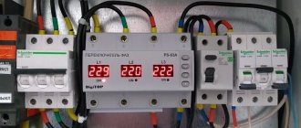
Input No. 1 and Input No. 2 are OK
The first input is the main one, the second one is the backup one. The device, through contacts A1, B1, C1, through the circuit breaker QF2, monitors the voltage at input-1. The same thing happens at input-2, through contacts A2, B2, C2.
Since all these contacts are normal, the AVR-02 should apply voltage to the KM coil. How does this happen?
Contacts 1 and 11 generate a control signal via relay K5. This relay K5, if the voltage level is normal on both inputs, should turn on input No. 1. That is, it is in the same position as in the original diagram. The voltage through it reaches pin 10 and goes to the KM4 coil. This is an intermediate relay. Its contacts are designated KM4.1 and KM4.2
The relay is triggered, closing its contacts and the voltage through them reaches the 22nd contact. Next, the AVR turns on relay K1. Through it and contact No. 24, the phase reaches the switching coil KM1. At the same time, other relays K2, K3, K4 remain open.