Before cutting a thread, it is necessary to select the diameter of the workpiece for this thread.
When cutting a thread with a die, you must keep in mind that when a thread profile is formed, the metal of the product, especially steel, copper, etc., stretches and the product increases. As a result, the pressure on the surface of the die increases, which leads to heating and adhesion of metal particles, so the thread may become torn.
When choosing the diameter of a rod for external threads, you should be guided by the same considerations as when choosing holes for internal threads. The practice of cutting external threads shows that the best thread quality can be obtained if the diameter of the rod is slightly smaller than the outer diameter of the thread being cut. If the diameter of the rod is less than required, the thread will be incomplete; if it is more, then the die either cannot be screwed onto the rod and the end of the rod will be damaged, or during operation the teeth of the die may break due to overload, and the thread will be torn off.
In table Figure 27 shows the diameters of the rods used when cutting threads with dies.
Table 27 Diameters of threaded rods when cutting with dies
The diameter of the workpiece should be 0.3-0.4 mm less than the outer diameter of the thread.
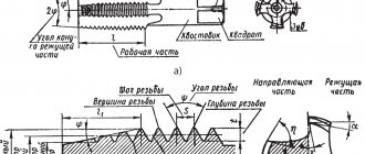
When cutting a thread with a die, the rod is secured in a vice so that the end of the vice protruding above the level of the jaws is 20-25 mm longer than the length of the part being cut. To ensure penetration, a chamfer is filed at the upper end of the rod. Then a die attached to the die is placed on the rod and with slight pressure the die is rotated so that the die cuts in approximately 0.2-0.5 mm. After this, the cut part of the rod is lubricated with oil and the die is rotated in exactly the same way as when working with a tap, i.e. one or two turns to the right and half a turn to the left (Fig. 152, b).
Rice. 152. Technique for cutting threads with a die (b)
To prevent defects and breakage of teeth, it is necessary that the die fits onto the rod without distortion.
Checking the cut internal threads is done with thread plug gauges, and external threads are checked with thread micrometers or thread ring gauges.
Despite the fact that cutting internal threads is not a complex technological operation, there are some features of preparation for this procedure. Thus, it is necessary to accurately determine the dimensions of the preparation hole for threading, and also select the right tool, for which special tables of drill diameters for threads are used. For each type of thread, it is necessary to use the appropriate tool and calculate the diameter of the preparation hole.
The thread diameter and through hole must comply with the standards, otherwise the grooves will come out too small and the threaded connection will be unreliable
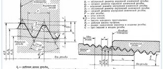
Types and parameters of thread
The parameters by which threads are divided into different types are:
- units of diameter (metric, inch, etc.);
- number of thread starts (one-, two- or three-thread);
- the shape in which the profile elements are made (triangular, rectangular, round, trapezoidal);
- direction of rise of turns (right or left);
- location on the product (external or internal);
- surface shape (cylindrical or conical);
- purpose (fastening, fastening and sealing, chassis).
Metric thread parameters
Depending on the above parameters, the following types of thread are distinguished:
- cylindrical, which is designated by the letters MJ;
- metric and conical, designated M and MK respectively;
- pipe, designated by the letters G and R;
- with a round profile, named after Edison and marked with the letter E;
- trapezoidal, designated Tr;
- round, used for installation of sanitary fittings, – Kr;
- thrust and thrust reinforced, marked as S and S45, respectively;
- inch thread, which can also be cylindrical and conical - BSW, UTS, NPT;
- used to connect pipes installed in oil wells.
Thread types according to GOST
Application of the tap
Before you start threading, you need to determine the diameter of the preparation hole and drill it. To facilitate this task, a corresponding GOST was developed, which contains tables that allow you to accurately determine the diameter of the threaded hole. This information makes it easy to select the drill size.
Read also: Electric heel cleaning device
To cut metric threads on the inner walls of a hole made with a drill, a tap is used - a screw-shaped tool with cutting grooves, made in the form of a rod, which can have a cylindrical or conical shape. On its side surface there are special grooves located along its axis and dividing the working part into separate segments, which are called combs. The sharp edges of the combs are precisely the working surfaces of the tap.
Tap: design and parameters
In order for the turns of the internal thread to be clean and neat, and for its geometric parameters to correspond to the required values, it must be cut gradually, by gradually removing thin layers of metal from the surface being treated. That is why for this purpose they use either taps, the working part of which is divided along the length into sections with different geometric parameters, or sets of such tools. Single taps, the working part of which has the same geometric parameters along its entire length, are needed in cases where it is necessary to restore the parameters of an existing thread.
The minimum set with which you can sufficiently perform machining of threaded holes is a set consisting of two taps - rough and finishing. The first one cuts a thin layer of metal from the walls of the hole for cutting metric threads and forms a shallow groove on them, the second one not only deepens the formed groove, but also cleans it.
Types of thread taps and their differences
Minimum set of taps
Combination two-pass taps or sets consisting of two tools are used for tapping small diameter holes (up to 3 mm). To machine holes for larger metric threads, you must use a combination three-pass tool or a set of three taps.
To manipulate the tap, a special device is used - a wrench. The main parameter of such devices, which can have different designs, is the size of the mounting hole, which must exactly match the size of the tool shank.
Some types of tap drivers
When using a set of three taps that differ both in their design and geometric parameters, the sequence of their use must be strictly observed. They can be distinguished from each other both by special marks applied to the shanks and by design features.
- The tap, with which the hole for cutting metric threads is processed first, has the smallest diameter among all the tools in the set and cutting teeth, the upper part of which is heavily cut off.
- The second tap has a shorter fence and longer combs. Its working diameter is intermediate between the diameters of the other tools in the set.
- The third tap, with which the hole for cutting metric threads is processed last, is characterized by full ridges of cutting teeth and a diameter that must exactly match the size of the thread being formed.
Set of three taps
Taps are used primarily for cutting metric threads. Much less often than metric ones, taps designed for processing the internal walls of pipes are used. In accordance with their purpose, they are called pipe, and they can be distinguished by the letter G present in their markings.
Mechanics of the process: we study in detail
Try to imagine what happens to the metal of the workpiece at the beginning of the movement of the threading tool. Its first few turns converge into a cone, forming the lead-in part. A little force is enough for the sharp and hard teeth of a die or tap to press small grooves into the metal and become firmly fixed in it.
That's it, now the tool, as they say, has “taken a step” and will precisely follow the spiral of the thread, becoming stronger the more turns there are. But the fact is that metal cannot deform indefinitely. If the tool's teeth cut too deeply, they will push out excess material, creating chips. If you cut a hole with a regular hardened bolt, chips will clog the newly cut thread and the tool will have to be constantly unscrewed to clean the hole. The tap and die have special grooves for chip removal.
It is very important to understand that the teeth of the working part do not cut grooves in the metal. They push them, squeezing out the metal on both sides of them. Removal of excess is carried out by a notch between adjacent teeth: it gives the ductile metal a shape, and the remainder is thrown into the chip groove.
Internal thread cutting technology
As mentioned above, before starting work, you need to drill a hole, the diameter of which must exactly fit a thread of a certain size. It should be borne in mind: if the diameters of the holes intended for cutting metric threads are chosen incorrectly, this can lead not only to poor quality execution, but also to breakage of the tap.
Considering the fact that the tap, when forming threaded grooves, not only cuts the metal, but also pushes it, the diameter of the drill for making threads should be slightly smaller than its nominal diameter. For example, a drill for making M3 threads should have a diameter of 2.5 mm, for M4 - 3.3 mm, for M5 you should choose a drill with a diameter of 4.2 mm, for M6 threads - 5 mm, M8 - 6.7 mm, M10 - 8.5 mm, and for M12 - 10.2.
Read also: Homemade dump trailer for walk-behind tractor
Table 1. Main diameters of holes for metric threads
Table 2. Diameters of holes for inch threads
All diameters of drills for GOST threads are given in special tables. Such tables indicate the diameters of drills for making threads with both standard and reduced pitches, but it should be borne in mind that holes of different diameters are drilled for these purposes. In addition, if threads are cut in products made of brittle metals (such as cast iron), the diameter of the thread drill obtained from the table must be reduced by one tenth of a millimeter.
You can familiarize yourself with the provisions of GOST regulating the cutting of metric threads by downloading the document in pdf format from the link below.
The diameters of drills for metric threads can be calculated independently. From the diameter of the thread that needs to be cut, it is necessary to subtract the value of its pitch. The thread pitch itself, the size of which is used when performing such calculations, can be found out from special correspondence tables. In order to determine what diameter the hole needs to be made using a drill if a three-start tap is used for threading, you must use the following formula:
To = Dm x 0.8, where:
Do is the diameter of the hole that must be made using a drill,
Dm is the diameter of the tap that will be used to process the drilled element.
Scheme of cutting internal threads with a tap
The drivers into which the threaded tap is inserted can have a simple design or be equipped with a ratchet. You should work with such devices with tools fixed in them very carefully. To obtain high-quality and clean threads, rotating the tap clockwise, performed half a turn, must be alternated with turning it one-fourth of a turn against the thread.
The thread will be cut much easier if you use a lubricant during this procedure. The role of such a lubricant when cutting threads in steel products can be played by drying oil, and when processing aluminum alloys - alcohol, turpentine or kerosene. If such technical fluids are not at hand, then ordinary machine oil can be used to lubricate the tap and the thread being cut (however, it has less effect than the substances listed above).
Threaded connections are widely used in various mechanisms and machines. Bolts, studs, screws, nuts are universal, interchangeable fasteners. However, there are times when it is necessary to cut threads by hand. A specialized tool will help you do this job efficiently.
In mechanical engineering, there are three main systems of fastening threads: metric, inch and pipe.
Metric thread has become the most widespread. It has a triangular profile with an angle of 60˚. Its main parameters, diameter and pitch, are expressed in millimeters. Designation example: M16. This means that the thread is metric, has a diameter of 16 mm with a coarse pitch of 2.0 mm. If the step is small, then its value is indicated, for example, M16 * 1.5.
The diameters of inch and pipe threads are expressed in inches. The pitch is characterized by the number of threads per inch. The specified parameters are standardized, so it is always possible to select the necessary tool.
APPENDIX 2
METHOD
FOR DETERMINING THE DIAMETERS OF HOLES FOR METRIC THREADING FOR MATERIALS OF HIGH VISCOSITY
1. General provisions
1.1. Materials of increased viscosity are understood as materials in which, due to increased elastic deformations and plastic properties, a significant rise in the coil (swelling) is observed.
1.2. The group of high-viscosity materials includes:
magnesium alloys according to GOST 804-93;
aluminum alloys according to GOST 4784-97;
high-alloy steels and alloys, corrosion-resistant, heat-resistant, heat-resistant (nickel-based) according to GOST 5632-72, GOST 20072-74.
1.3. In table 1 shows the coil lift coefficients for some types of difficult-to-process materials of high viscosity.
2. Calculation of hole diameter
2.1. The diameter of the hole for threading is calculated using formulas (1). (4).
2.2. Nominal (smallest) hole diameter d
0 nom is determined by the formula
where D
1 - nominal internal diameter of the nut thread, mm;
EI – lower limit deviation of the internal diameter of the thread according to GOST 16093-81, mm;
A
– the magnitude of the rise of the coil, determined from the table. 1. When calculating the diameters of holes for a group of materials, substitute the largest value of the thread lift value for a given thread pitch into the formula.
2.3. Largest hole diameter d
0 naib is determined by the formulas:
a) for a specific material
where EI + TD1 is the upper limit deviation of the internal diameter of the thread according to GOST 16093-81, mm;
A
– the magnitude of the rise of the coil, determined from the table. 1;
b) for a group of materials
where A
– the smallest value of the turn lift value for a given thread pitch.
2.4. Hole diameter tolerance D d
determined by the formula
2.5. An example of calculating the diameter of a hole for an M10 thread with a tolerance range of 6H ( P
= 1.5 mm;
D
1 = 8.376 mm;
EI = 0; EI + TD1 = 0.300 mm) for a group of materials (the largest value of the coil lift value A
= 0.255, the smallest value of the coil lift value A = 0.110).
1. d
0 nom = 8.376 + 0 + 0.255 = 8.631 mm.
Round up to d
0 nom = 8.63 mm.
2. d
max =8.376 + 0.300 + 0.110 = 8.786 mm.
Round up to d
0 max = 8.79 mm.
3. D d
= 8.79 – 8.63 = 0.16 mm.
4. Hole diameter 8.63 +0.16 mm.
2.6. The dimensions and maximum deviations of the diameters of holes for threads with large pitches are given in table. 2, for threads with fine pitch - in table. 3.
2.7. It is recommended to clarify the maximum dimensions of hole diameters on the first 3–5 products of a batch, depending on the mechanical properties of the materials being processed, melting, heat treatment and other technological factors.
2.8. The diameters of drills for threading in materials of high viscosity are given in table. 4.
Despite the fact that cutting internal threads is not a complex technological operation, there are some features of preparation for this procedure. Thus, it is necessary to accurately determine the dimensions of the preparation hole for threading, and also select the right tool, for which special tables of drill diameters for threads are used. For each type of thread, it is necessary to use the appropriate tool and calculate the diameter of the preparation hole.
Read also: How to make a degausser with your own hands
The thread diameter and through hole must comply with the standards, otherwise the grooves will come out too small and the threaded connection will be unreliable
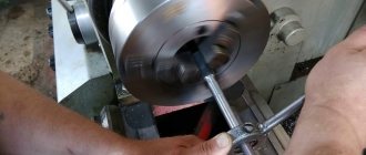
External thread cutting with a die
To cut external threads, you will need the following tools and materials: a die or pipe clamp, a die holder, a file, a vice, a caliper, and machine oil.
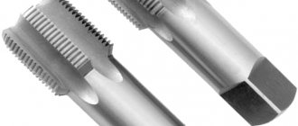
The most widespread are round dies (lerks). They are either solid or split. The diameters of solid round dies are standardized. This allows you to choose the appropriate option from a large range of sizes, for example, M10, M12, M14, M16.
A special feature of split dies is the ability to adjust the diameter of the thread being cut within 0.1…0.25 mm. However, they have reduced rigidity, which affects the accuracy of the resulting profile.
The die is installed in a die holder of a suitable size. After this, it is secured with screws. In the case of external pipe threads, die holders with a ratchet are often used. They provide convenience for working in hard-to-reach places, such as near a wall.
Read also: How to remove a magnetic field
The thickness of the rod is chosen to be 0.1...0.25 mm less than the diameter of the external thread. For example, for M6 with a large pitch it is 5.80...5.90 mm; M8 – 7.80…7.90 mm; M10 – 9.75…9.85 mm. Measurements are taken using a caliper. The diameters of rods for cutting metric threads of average accuracy class 6g are presented in the table.
To ensure better insertion of the die, a chamfer is filed at the end of the rod. Its width should be 1 - 1.5 mm for M6 ... M18. The workpiece is lubricated with machine oil, which makes subsequent work easier and allows you to obtain a better surface.
The die is placed on the end of the rod so that its plane is perpendicular to the axis of the bolt being cut. Next, with slight pressure, rotate the die holder clockwise (if the thread is left-handed, then counterclockwise). When the die cuts into the rod by one or two threads, it should be turned back half a turn for better removal of chips. After this, they again make 1-2 turns along the thread and 0.5 in the opposite direction. Using this scheme, the bolt is cut to the required length.
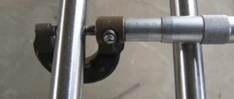
The diameter of the external thread is checked with a regular nut or ring gauge. If necessary, the pitch is controlled with a thread gauge.
One-pass method
Single-start thread cutting is typical for mechanized devices. A single-cut tap has one wide or three thin grooves on the shank, or may have none at all. Other differences between machine taps: a short lead, a shank thinner than the nominal diameter, and a full thread profile.
You can cut through threads in thin (2–4 mm) sheet materials in one go. Machine taps are also very common for cutting blind holes. More precisely, they widen the trace from the leading part of taps #1 and #2, adding another 1.5–2 turns to the thread. If the third number has a long lead, you can cut it off completely and use this tap only for full threading in blind holes.
Single-start taps are no more difficult to work with than dies. There is difficulty in setting the correct position, but the technique is the same. By the way, most dies are also designed for single-pass operation.