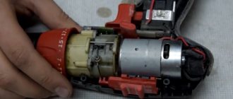
Now you have to use a soldering iron and unsolder the two elements from each other, as shown in the figure. Screwdriver design: 1 - speed controller with reverse, 2 - electric motor, 3 - gearbox. Resistor Rx sets the highest current.
The graph shows how the temperature of the element temperature, the voltage at its terminals voltage and the relative pressure relative pressure change during charging. It can monitor battery parameters and, if necessary, reduce the current automatically. WE MAKE A SIMPLE BATTERY CHARGER with auto shutdown when fully charged
The electrical signal is supplied directly to the engine rotor through the commutator. Next, you need to carefully assemble the screwdriver button, install it in place and test it.
When the breakdown occurred, I was on business in Orenburg and therefore contacted the service center for repairs there.
Replaceable battery.
The rather miniature size of this tool assembly is achieved using microfilm technology.
We visually inspect the condition of the button for dirt and damage. repairing a screwdriver, replacing the power button with your own hands
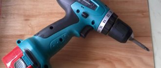
General view of the screwdriver
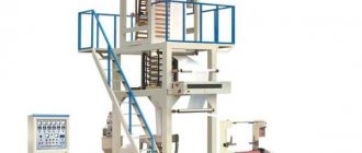
Screwdrivers can be corded or corded. The difference between them is the power source. The shape of the tool is similar to a pistol. The screwdriver design and general view are shown in the photo.
A screwdriver is structurally similar to an electric drill and consists of the following components:
- a body that smoothly turns into a handle and a support leg to which the battery is attached and there is a cavity - a block for storing bits.
- Control buttons;
- Battery or power cord.
Instrument power supply
The supply of DC power to the electric motor of the screwdriver is carried out from a 220 volt network or using a battery. It is produced in a small-sized and compact design. This is necessary to reduce the weight of hand tools and ensure ease of work. The power supply device consists of several galvanic elements.
The batteries are combined into one housing and form a single unit. The supply voltage, depending on the scope of application of the screwdriver, may be different. For household equipment it is 9 volts, and for professional models it can reach 18 volts. The power of a power tool is directly proportional to the amount of voltage supplied.
Using information about the structure of the tool’s mechanisms, a person will be able to repair the screwdriver himself, saving time and money.
Screwdriver body
The power tool is “packaged” in a plastic case, a material with the following advantages:
- Plastic serves as a natural insulator from electricity; it does not conduct electricity. Therefore, it is safe.
- It is lighter than metal, and thus reduces the weight of the tool.
- And finally, in production, plastic is easier to shape into the desired shape than metal.
The body is conventionally divided into three parts. All rotating mechanisms are located in the upper part. The handle is equipped with soft pads. The master holds the tool with it while working. The pads reduce shock absorption, making work more comfortable and easier. The lower part, the support, inside of which there is a compartment for storing bits.
History of the device
A screwdriver is a power tool.
Its main purpose, as the name suggests, is to tighten or unscrew a fastener. After the electric drill was invented in 1868, the development of power tools became widespread. Founding companies DeWalt, Bosch, Black & Decker, Makita and Hitachi developed the industry by creating new devices. The introduction of the Phillips head screw in 1934 created a demand for electric tools to tighten them. It was especially in demand in mechanical engineering. The first device of this kind was called a wrench. With the advent of batteries, the device gained mobility, and the name screwdriver came into use. Its mass production began in the early 80s .
Modern devices are constantly improving, but to a greater extent this relates to the method of autonomy and control. The design of the device remains unchanged.
This is interesting: Concrete drill bits for drills: types and models
Trigger switch and LED lighting
The trigger switch is located between the top of the housing and the handle. It is located under the master’s index finger, and it is convenient to use it to put the tool into operation. The trigger button closes the electrical network of the screwdriver and starts the electrical mechanisms.
The photo shows the device of the trigger button.
Some models of screwdrivers have built-in LED lighting that illuminates the work area. This is prudent and convenient, since in dimly lit areas it can be difficult to see the screw slot. In the model shown in the picture, the backlight is located in the lower part of the body above the trigger; in some Western European models it is located on the leg above the battery.
Speed control unit and speed switch
The rotation speed and reverse (rotation direction) control unit is connected to a PWM controller, a multi-channel single-pole transistor and a variable resistor, which are hidden in the switch block.
To change the direction of rotation, a changeover contact is used, to which a reverse switch is connected, located above the trigger at the bottom of the screwdriver. It is connected to a changeover contact, which changes the polarity of the voltage supplied to the electric motor. Thanks to this, the direction of rotation changes, which allows screws, self-tapping screws, and screws to be screwed in and out.
Another button is a gearbox speed switch which changes the rotation speed of the chuck. This occurs due to the fact that when the speed button is turned from one mode to another, the bracket (rocker arm) comes into motion, moving the gearbox gear from one level to another.
Transistors STP60NF06. Screwdriver repair
At some point, during a cold start (after storage), the screwdriver began to ignore the force of pressing the button, immediately turning on the maximum speed.
After rummaging around on the net, I decided to first clean the insides of the button, since there was a possibility that the problem was the accumulated metal filings on the sliding contacts. I still don’t understand whether this is true, because during the assembly process I mixed up the polarity of the insert diode, which led to the transistor burning out. So I had to order a new one. To understand what I did wrong, I found a diagram of a button on the same chip as mine (GS069). It is slightly different; instead of a resistive track (potentiometer), I have tracks for resistive dividers on the board, but otherwise the circuit is the same. I noticed in time that both diodes in the diagram are shown with reversed polarity, otherwise it would have burned out another transistor. The mentioned insert diode does not have any markings and looks like a small iron washer with insulation around the perimeter; next time I disassemble the button, I will take a photo and show it here. Polarity is determined by a multimeter in dial mode.
I saw ready-made assemblies with a transistor and a button in a local store, they cost from 400 rubles. Perhaps the entire assembly should have been replaced at once, given the noticeable wear of the contacts, but I decided to save money; it was better to buy a normal tool for the money. Or, for a thousand and a half, you can rent just another Chinese screwdriver for the season with new gears, a motor, and a button. Replace it with a good battery and continue buzzing quietly.
At the time of delivery of the new transistor, I installed the less powerful IRFZ24N (17 A versus 60 A and 55 W versus the old 110 W); I couldn’t find anything else. The transistor is the same type, I was not afraid of compatibility. In all modes with the limit clutch turned on, the screwdriver does not develop enough power so that even such a relatively weak transistor is not enough. The mosfets parallel well; for reliability, you could assemble a sandwich from a couple of IRFZ24Ns.
I temporarily decided not to use the tool in difficult situations when it was necessary to remove restrictions, but my plans were disrupted when I urgently had to unscrew a hefty screw. At the maximum limit, the protection (ratchet) was constantly activated, the screw did not budge. I took a risk by setting the drill mode (without restrictions), and calmly did the job. But now the button again stopped responding to gradual pressure, immediately turning on the engine to maximum.
Having disassembled the screwdriver, I discovered that the replacement transistor had burned out and all its leads were short-circuited. I don’t know whether such transistors can burn out gradually. If so, then it is likely that the previous soft start problem could have been caused by the transistor. Perhaps installing a more powerful battery somehow affected the life of the transistor. New transistors were still on the way, so I inserted a second spare IRFZ24N for now. It was necessary to immediately put the pair in parallel, perhaps they would have pulled out a larger load, but it was not clear how to install both of them on a standard radiator. In general, I was lazy and paid the price.
Let's return to the order. I am 100% sure that the transistors ordered are not originals, because this is AliExpress, and there they only look for originals... but no one looks for them, everything is so obvious. On the other hand, I'm almost sure that the old transistor was fake too. The tool is Chinese, the likelihood of imported parts getting into it if there are cheap ones of our own is very unlikely.
There are no difficulties with installation. It makes sense to shorten the legs so they don't get in the way. The wires are soldered to the legs of the transistor with minimal overlap, so that later the soldering area can be covered with a plastic insulator. You can put thermal paste under the transistor. Initially it was not there, the surface under the transistor is uneven, but the transistor almost does not heat up during operation. The legs are tinned well, there were no problems with soldering, except that the legs are a bit soft and you need to handle them carefully; the legs of the old transistor are also soft.
I didn’t bother assembling a test bench or measuring the characteristics of the transistors, and I simply had nothing to drive them to the maximum parameters, except perhaps with a screwdriver itself, which is what I did. From past experience, I already knew that I still had to try harder to load the tool, so I immediately took a 6-mm screw under the PZ3 head and tried to screw it into a wooden block. The first 5 cm passed on the last tick of the fuse, after which the ratchet engaged. I set it to “drill” (unlimited mode) and drove the screw all the way.
And this is where things started to get interesting. White smoke with a noticeable odor began to emerge from under the ventilation grille. Burnt transistors smell different, most likely the motor windings are stinking. I quickly took the screwdriver apart and rummaged around everything inside. The button and the motor are the hottest, but the transistor is a little warm and intact. The smell is from the engine. This is not the first time that smoke has come out of this screwdriver; it also happened on the old battery, while it was fresh, under a heavy and long load, that is, this behavior of the tool seems to be normal :-), and the new transistor is not to blame.
The transistor has clearly coped with the maximum developed power of the instrument, and so far there are no complaints about it. I’ll add to this post later, the summer season is ahead, there will be something to check.
In stores you can find it under the line “stp60nf06”. You can also look for more powerful transistors, supply and demand may work in their favor. Lots less than 5 pieces seemed to me unnecessarily expensive (per piece), five pieces cost 130 rubles (26 rubles/piece). In the nearest local radio parts store I could buy them individually for 30-35 rubles per piece, but with transport or delivery it would be another +300 rubles, at a minimum. It is very likely that they are even original, but in practice it turned out that imitation is enough.
Update dated May 19, 2016
Coincidentally, during the first real use of the screwdriver after replacing the transistor, it suddenly rattled loudly and stopped turning the chuck. It turned out that the engine had unscrewed from the gearbox unit. If your screwdriver starts making rattling sounds, you may have the same problem - loosening of the mounting screws, which will eventually lead to their complete unscrewing. It’s easy to check - the engine and gearbox unit must be firmly connected, without play.
There is nothing to do with replacing the transistor, other than a coincidence in time
Chuck with locking mechanism
A planetary gearbox transmits torque to a shaft onto which a self-centering chuck with attachments or bits inserted into it is screwed. The quick-release chuck ensures the fixation of screwdriver and drill bits; it consists of a holder, inside of which there is a clamping sleeve with movable jaws.
The shaft to which the chuck is screwed is equipped with a locking mechanism, which consists of an outer and inner housing and rollers installed between the housings and preventing rotation.
Rechargeable battery with locking button
Since the screwdriver can be cordless and wired, the power supply system in them is different. The cordless screwdriver has a built-in rechargeable battery, which is a device with built-in external contacts for transmitting electricity. The main element of the battery is its power supplies connected in series. Otherwise they are called banks, sample in the photo.
It also has a thermostat that protects the battery from overheating when charging. The rechargeable battery is a removable device, since it must be replaced as the resource is exhausted. The battery is attached to the screwdriver with a locking button, which is located on the side in some models, and in the front in others. From the handle extend contact plates that connect to the battery and provide power.
Tips for using an electric screwdriver
When the 12-18 volt power supply is assembled, the screwdriver becomes mains-powered. It must be used according to the rules:
- every 20 minutes of work, take a break for 3-5 minutes to allow the block element to cool down;
- If you operate an external unit, make sure it is clean. It should not be dusty or dirty. This will cause the device to heat up faster and work less efficiently;
- the updated tool cannot be used at a height of more than 200 centimeters;
- equip the element with a residual current device. If there are problems with the network, the RCD will save the equipment from breakdown;
- All wires must be securely soldered.
Engine
Now let's look inside the screwdriver body. The photo shows a cutaway screwdriver, or rather, with the cover removed.
A DC motor converts electrical current into mechanical energy, causing machinery to rotate. This is what the electric motor looks like in some power tools.
An electric motor consists of a stationary stator and a rotating rotor. The stator is a cylindrical metal casing with permanent magnets built around its walls.
Inside the housing there is a rotating rotor. It consists of a shaft on which a core is attached, which is a connection of plates made of high-tech steel, in the grooves of which winding turns of special copper wire are laid. When electrical energy is supplied, the rotor begins to rotate under the influence of these magnets and, through a gear pressed onto the shaft, transmits rotation to the planetary gearbox.
The circuit is connected to the motor through a brush mechanism consisting of two graphite brushes located opposite each other. During operation, the graphite brushes are gradually worn out, but pressure springs ensure their contact with the commutator.
Brushes are consumable parts and if the engine does not start, they are the first thing to check. The impeller serves to remove hot air and cool the engine. In the housing, opposite the impeller, there is a radiator grille.
Planetary reductor
The drive sun gear is also pressed onto the rotor shaft. A bracket in the form of a rocker arm is mounted on the engine body, with the help of which the gear stages are switched.
Screwdriver gearbox
The differential gearbox can be enclosed in a plastic housing. The arrangement of gears in a planetary gearbox depends on the number of switched speeds and may differ in different models. In a two-speed power tool, the gearbox has three stages. The first stage contains:
- sun gear;
- fixed ring gear;
- planet gears, small gears that rotate inside the ring gear.
- toothed drive.
The second stage serves to transition from the first stage to the third when changing gears. It consists of a planetary gear, which, with the help of a bracket, moves to the first and second rows of gears, due to which the rotation speed of the cartridge changes. It also has built-in satellites and carrier. The third stage is connected to a crown gear with protrusions at the end, 5 satellites, and a carrier with a cross-shaped grip.
The tightening torque clutch (the force applied by the screwdriver when performing work), also known as the torque regulator, consists of cylinders and balls, a housing, a washer, and a spring.
The clutch blocks the operation of the screwdriver if the load on the rotation mechanism increases, and thereby protects the screws on one side from failure, and the engine and planetary mechanism from unnecessary overloads and premature failure.
If you switch the screwdriver to drilling mode, the spring tightens and presses the washer as much as possible so that the third stage ring gear is blocked and its rotation is prevented. Thanks to this, the operation of the cartridge is not blocked. This video shows how a screwdriver works.
Disassembling a screwdriver
Most often, in order to find a fault and repair the device, you will need to disassemble it. Since all devices are similar in appearance, resembling the shape of a pistol, their disassembly can be presented in the form of recommendations given for repairing an Interskol screwdriver:
- First of all, the battery pack is disconnected. This will require
press the latch and unfasten the module. - Unscrew all the screws around the perimeter of the device using a Phillips screwdriver.
- After unscrewing the screws, the two halves of the housing are separated, while holding the structural parts installed in the grooves.
- The speed switch, start button and reverse mechanism are carefully disconnected.
- The gearbox is removed from the removed half. To remove it, you will need to rotate the gearbox in its seat.
Assembly occurs in reverse order . In this case, it is necessary to ensure that all removed elements and wires are located in specially made recesses for them.
To lubricate the mechanical parts or restore the gearbox, the latter often has to be disassembled. To do this, first remove the protective plate, then unscrew the screws in a circle and remove the top cover. Viscous materials, for example, Litol, are used as lubricants. It is important to note that it is almost impossible to carry out serious repairs to a screwdriver gearbox with your own hands, since gears are not produced separately by manufacturers. Therefore, if it is damaged, you will have to replace the entire unit.
The next element that has to be disassembled is the cartridge. It is a quick-clamping design that is secured with a threaded connection, a screw, or a Morse taper. With the first method, you will need to unscrew the fastener using a hex key, and then, placing the key in the chuck, tighten it tightly. The cartridge is unscrewed by turning the key.
With the second type of connection, use a screwdriver to unscrew the screw located in the middle of the chuck jaws counterclockwise. Next, having installed and clamped the L-shaped key in the jaws, with a sharp movement the key must be turned counterclockwise. Removing the fastener using a Morse taper occurs by carefully striking the end of the cartridge.
Features of corded and cordless screwdrivers
In corded screwdrivers, the power source is a 220V electrical network and a power cord is built into the handle of the power tool. To work with corded power tools, an electrical outlet is required; this is a disadvantage of such tools. However, a constant power source and voltage of 220 V do not limit the power of such power tools. It's no secret that batteries are limited in this regard. They are also limited by operating time, after which the battery must be charged.
A cordless screwdriver with a rechargeable battery is appreciated by motorists who have to carry out repairs in the absence of a constant power supply, somewhere on the highway, and by builders, since remote construction sites are not always provided with electricity in a timely and stable manner.
Battery Disadvantages
- Needs regular recharging. Sooner or later, batteries will exhaust their recharge cycle life.
- The cheaper the tool, the faster the time for rework will come.
There is nothing wrong with this, but you should be aware: the manufacturer saves as much as you do. Consequently, the most expensive unit (and this is the battery) will be the cheapest when completed.
As a result, we get an excellent tool with a working engine and a non-worn gearbox, which does not work due to a low-quality battery.
There is an option to purchase a new set of batteries, or replace faulty batteries in the unit. However, this is a budget event. The cost is comparable to buying a new screwdriver.
The second option is to use a spare or old car battery (if you have one). But the starter battery is heavy, and using such a tandem is not very comfortable.
IMPORTANT! Many screwdrivers have an operating voltage of 16-19 volts. Even a fully charged car battery will not provide such voltage. And we mean using a used battery, where there can be a maximum of 10.5-11.5 volts at the terminals.