Objects intended for transportation or storage of liquid and gaseous substances must be subject to control of the tightness of welded joints. The tightness test is carried out by the company's quality control department. Periodic monitoring during operation is carried out by the owner within the time limits determined by regulatory documents.
Quality control of welded joints
The kerosene test is as follows.
The side of the welded joint accessible for inspection is painted with an aqueous suspension of chalk or kaolin. For quick drying, it is recommended to apply the suspension to the seam that has not cooled down after welding, when its temperature drops to approximately 50-70°C. After the suspension has dried, the opposite side of the joint is thoroughly moistened with kerosene two or three times. When checking lap joints, kerosene is supplied into the lap gap under an excess pressure of at least 1.5 kg/cm 2 .
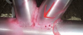
If there are leaks in the connection, then dark or slightly yellowish greasy kerosene stains appear on the chalk-painted surface. The duration of the test is from 15 minutes to several hours, depending on the thickness of the seam, the type of welded joint and its location in space.
If access to welded joints is open only on one side, kerosene is applied to this side two or three times in a row.
After 15-20 minutes, the seams are thoroughly wiped dry with rags. In order for the kerosene that has been absorbed into the defective areas to quickly reach the surface of the seam, the metal in the area of the welded joint is tapped with light blows of a hammer with a rounded head.
It is even better to subject the product to vibration, for example, using a concrete vibratory compactor. With this inspection method, it is possible to detect not only through, but also non-through defects that appear on the surface.
The ability of kerosene to penetrate through the smallest leaks in seams is explained by its non-polarity, high wetting ability, low viscosity, as well as the ability to dissolve oil films and plugs that can clog leaks.
When non-polar liquids (kerosene and other hydrocarbons) interact with leaky walls, the viscosity of the wall and central layers of the liquid is the same. Therefore, despite the fact that the viscosity of water is two times less than the viscosity of kerosene, the latter, due to its non-polarity, penetrates better into micro-leaks.
Using kerosene, you can detect leaks with a diameter of up to several ten-thousandths of a millimeter.
The sensitivity and performance of the kerosene test method can be improved by using it in combination with the vacuum method. The essence of such a kerosene-vacuum test (see Fig. 181) is as follows.
After wetting the seam with kerosene, a vacuum chamber is installed, with the help of which a difference in air pressure is created. The difference in air pressure together with the capillary pressure of kerosene increases the control efficiency.
Legislative framework of the Russian Federation
Free legal aid hotline
- Encyclopedia of mortgages
- Codes
- Laws
- Document forms
- Free consultation
- Legal encyclopedia
- News
- about the project
Free consultation
Navigation
Federal legislation
- Constitution
- Codes
- Laws
Actions
- home
- “RULES FOR THE CONSTRUCTION OF VERTICAL CYLINDRICAL STEEL TANKS FOR OIL AND PETROLEUM PRODUCTS. PB 03-381-00" (approved by Resolution of the State Mining and Technical Supervision of the Russian Federation dated September 27, 2000 N 55) (as amended on November 21, 2002)
7.4. Leak control
7.4.1. All welds that ensure the tightness of the tank, as well as the buoyancy and tightness of the pontoon or floating roof are subject to leak testing.
7.4.2. Testing the tightness of welds using the chalk-kerosene test should be done by abundantly wetting the seams with kerosene. No stains should appear on the opposite side of the weld, previously coated with an aqueous suspension of chalk or kaolin. The duration of testing by the capillary method depends on the thickness of the metal, the type of weld and the test temperature. A conclusion about the presence of through defects in a welded joint is made no earlier than 1 hour after applying an indicator of through and surface defects to the seam.
7.4.3. When using a vacuum method for monitoring the tightness of welds, vacuum chambers must create a vacuum above the controlled area with a pressure drop of at least 250 mm water column. The pressure drop should be checked with a vacuum gauge. Weld seam leakage is detected by the formation of bubbles in a soap or other foaming solution applied to the weld joint.
7.4.4. It is allowed not to check the tightness of butt joints in wall sheets with a thickness of 12 mm or more.
7.4.5. Pressure testing is used to check the tightness of welds when welding reinforcing sheet linings of hatches and pipes on the walls of tanks. Control is carried out by creating excess air pressure from 400 to 4000 mm water column. in the gap between the tank wall and the reinforcing pad using a control hole in the reinforcing pad for this purpose. In this case, a soap film, a film of linseed oil or another foaming substance must be applied to the welds, both inside and outside the tank, to detect leaks. After testing, the inspection hole must be filled with a corrosion inhibitor.
7.4.6. It is recommended to monitor the tightness of welded joints on tank roof decks during hydraulic and pneumatic tests by creating excess air pressure inside the tank up to 150-200 mm water column.
Application area
1.1. This standard applies to adsorption gas purifiers (hereinafter referred to as adsorbers) with a fixed bed, moving granular adsorbent, fluidized dust-like adsorbent of vertical or horizontal type and other devices similar in functionality [1].
Adsorbers are designed to absorb gases or vapors from gas mixtures with solid absorbers (adsorbents) [2].
This standard can be used for the certification of adsorbers.
The requirements of this standard are mandatory.
Normative references
This standard uses references to the following standards:
GOST 12.1.005-88 System of occupational safety standards. General sanitary and hygienic requirements for the air in the working area.
GOST 12.1.010-76 System of occupational safety standards. Explosion hazard. General requirements.
GOST 12.2.003-91 System of occupational safety standards. Production equipment. General safety requirements.
GOST 12.2.049-80 System of occupational safety standards. Production equipment. General ergonomic requirements.
GOST 12.4.011-89 System of occupational safety standards. Protective equipment for workers. General requirements and classification.
GOST 17.2.3.02-78 Nature conservation. Atmosphere. Rules for establishing permissible emissions of harmful substances from industrial enterprises.
GOST 17.2.4.06-90 Nature conservation. Atmosphere. Methods for determining the speed and flow rate of gas and dust flows emanating from stationary sources of pollution.
GOST 17.2.4.07-90 Nature conservation. Atmosphere. Methods for determining the pressure and temperature of gas and dust flows emanating from stationary sources of pollution.
GOST 17.2.4.08-90 Nature conservation. Atmosphere. Methods for determining the humidity of gas and dust flows emanating from stationary sources of pollution.
GOST 5264-80 Manual arc welding. Welded connections. Main types, structural elements and dimensions.
GOST 7512-82 Non-destructive testing. Welded connections. Radiographic method.
GOST 8713-79 Submerged arc welding. Welded connections. Main types, structural elements and dimensions.
GOST 11533-75 Automatic and semi-automatic submerged arc welding. Welded connections at acute and obtuse angles. Main types, structural elements and dimensions.
GOST 11534-75 Manual arc welding. Welded connections at acute and obtuse angles. Main types, structural elements and dimensions.
GOST 14249-89 Vessels and apparatus. Norms and methods of strength calculations.
GOST 14771-76 Arc welding in shielding gas. Welded connections. Main types, structural elements and dimensions.
GOST 14776-79 Arc welding. Spot welded connections. Main types, structural elements and dimensions.
GOST 14782-86 Non-destructive testing. Welded connections. Ultrasonic methods.
GOST 14806-80 Arc welding of aluminum and aluminum alloys in inert gases. Welded connections. Main types, structural elements and dimensions.
GOST 15164-78 Electroslag welding. Welded connections. Main types, structural elements and dimensions.
GOST 15878-79 Contact welding. Welded connections. Structural elements and dimensions.
GOST 16037-80 Welded connections for steel pipelines. Main types, structural elements and dimensions.
GOST 16038-80 Arc welding. Welded connections for pipelines made of copper and copper-nickel alloy. Main types, structural elements and dimensions.
GOST 23518-79 Arc welding in shielding gases. Welded connections at acute and obtuse angles. Main types, structural elements and dimensions.
GOST 27580-88 Arc welding of aluminum and aluminum alloys in inert gases. Welded connections at acute and obtuse angles. Main types, structural elements and dimensions.
Definitions
In this standard, the following terms with corresponding definitions apply:
3.1. adsorption:
Absorption of gases or vapors from gas mixtures by a solid absorbent (adsorbent).
3.2. adsorber:
An apparatus for absorbing gases or vapors from gas mixtures with solid absorbers.
3.3. adsorbent:
Solid absorbent for trapping vapors or gases.
3.4. adsorber with fixed adsorbent:
A device in which the adsorbent layer does not change its position during the technological process.
3.5. adsorber with a moving layer of adsorbent:
An adsorbent in which a layer of adsorbent moves through the apparatus from top to bottom.
3.6. fluidized bed adsorber:
An adsorber in which adsorbent particles move intensively in a flow in various directions.
3.7. desorption:
Thermal regeneration of spent adsorbent, accompanied by the release of absorbed harmful substances.
Safety requirements
4.1. General safety requirements according to GOST 12.2.003.
4.2. Each adsorber, used independently or as part of a technological complex, is equipped with operational documentation (ED) containing requirements (rules) to prevent the occurrence of dangerous situations during installation (dismantling), commissioning and operation.
4.3. The adsorber must meet safety requirements throughout the entire period of operation provided that the consumer fulfills the requirements established in the ED.
4.4. The design of adsorbers must exclude, in all operating modes, loads on parts and assembly units that can cause destruction that poses a danger to workers.
If loads may arise that lead to dangerous destruction of individual parts or assembly units for workers, the adsorber must be equipped with devices that prevent the occurrence of destructive loads, and the parts and assembly units must be fenced or located so that their collapsing parts do not create traumatic situations.
4.5. The design of the adsorber and its individual parts must exclude the possibility of them falling, overturning and spontaneous displacement during operation and installation (dismantling). If, due to the shape of the adsorber, the mass distribution of its individual parts and (or) installation (dismantling) conditions, the required stability cannot be achieved, then means and methods of fastening must be provided that meet the requirements contained in the ED for a specific adsorber.
4.6. Structural elements of adsorbers should not have sharp corners, edges, burrs or surfaces with unevenness that pose a risk of injury to workers.
4.7. Parts of the adsorber (including pipelines of hydraulic, steam, pneumatic systems, safety valves, cables, etc.), the mechanical damage of which may cause danger, must be protected by guards or located so as to prevent their accidental damage by operating or maintenance equipment .
4.8. The design of the adsorber must prevent spontaneous loosening or disconnection of fastenings of assembly units and parts.
4.9. The adsorber must be fire- and explosion-proof under operating conditions.
4.10. The design of the adsorber must be made in such a way as to exclude the accumulation of static electricity charges in quantities that pose a danger to the worker, and the possibility of fire and explosion.
4.11. The adsorber should not be a source of noise and vibration. The design of the adsorber must be made so that the concentration of harmful substances in the working area, as well as their emissions into the natural environment during operation, do not exceed the permissible values established by GOST 12.1.005 and GOST 17.2.3.02.
4.12. An adsorber designed to work with an explosive gas environment must meet the requirements of GOST 12.1.010 and be equipped with devices that remove a directed blast wave.
Adsorber seals designed to work with fire and explosive substances must prevent the formation of flammable and explosive mixtures in the operating and non-operating state of the adsorber.
4.13. The design of the adsorber must exclude the possibility of contact with hot parts or being in close proximity to such parts, if this could lead to injury or overheating of the worker.
The temperature of the outer surface of the shell with thermal insulation in service areas should be no more than 45 ° C.
The thermal insulation of the adsorber must be made of mineral or organic heat-insulating materials. The thermal insulation layer, if necessary, must be protected by a waterproof shell.
If the purpose of the adsorber and the conditions of its operation (for example, use outside industrial premises) cannot completely exclude contact of a person working with the hot parts of the adsorber, then the ED must contain a requirement for the use of personal protective equipment.
4.14. The design of the workplace, its dimensions and the relative arrangement of elements (controls, information display devices, auxiliary equipment, etc.) must ensure safety when using the adsorber for its intended purpose, maintenance, repair and cleaning, taking into account the substances used in the technological process, as well as meet ergonomic requirements according to GOST 12.2.049.
The need for fire extinguishing means and means used in emergency situations at workplaces should be established in standards and regulatory documents for adsorbers of specific groups, types, models (brands).
If the location of the workplace makes it necessary to move and (or) stay the worker above the floor level, then the design of the adsorber should include platforms, stairs, railings, other devices, the size and design of which should exclude the possibility of workers falling and ensure convenient and safe performance of labor operations, including maintenance operations.
4.15. The design of adsorbers must ensure the safety of workers during installation (dismantling), commissioning and operation, both in the case of autonomous use and as part of technological complexes, subject to the requirements (conditions, rules) provided for in the ED.
4.16. Adsorbers must be equipped with signaling and blocking devices that are triggered when the established technological operating mode is violated.
4.17. Service personnel who have studied their design and maintenance techniques are allowed to service adsorbers.
4.18. The design of adsorbers must be designed for the maximum operating (excess) pressure or vacuum that may arise during their operation.
Test methods
5.1. The appearance, completeness and quality of installation of adsorbers are checked by visual inspection of the assembled equipment and its individual elements. During the inspection, it is necessary to make sure that there are no foreign objects inside the adsorber body and check the condition of thermal insulation and anti-corrosion coatings, check the readiness of places for connecting measuring instruments, the quality of installation of valves and hatches, the quality of welds and connections that determine the tightness of the equipment.
5.2. The overall dimensions of the adsorber are checked using length measuring instruments used at the manufacturer.
5.3. The mass of the adsorber is checked by weighing the empty adsorber assembly or its parts on a scale or using a dynamometer in accordance with the RD for a specific adsorber.
5.4. When manufacturing an adsorber, the quality of welds made by arc welding in accordance with GOST 5264, GOST 11534, GOST 14771, GOST 14776, GOST 14806, GOST 16037, GOST 16038, GOST 27580, gas-shielded welding in accordance with GOST 23518, submerged arc welding in accordance with GOST 8713 , GOST 11533, electroslag welding according to GOST 15164; resistance welding according to GOST 15878, checked by the following methods:
— visual inspection and measurement;
— test for resistance to intergranular corrosion;
— measuring the hardness of the weld metal;
— color or magnetic particle flaw detection;
— other methods (acoustic emission, luminescent control, determination of ferrite phase content, etc.) provided for in the RD for a specific adsorber.
5.5. After the designated service life, the adsorber is tested for reliability of further service by checking the thickness of the housing walls using the ultrasonic method in accordance with GOST 14782, radiation - in accordance with GOST 7512 or another method determined by the developer, and compliance of the main technical indicators with the RD for the adsorber is established.
5.6. Leak test
The method for checking the adsorber for leaks is determined by the developer.
Testing of welds for through defects is carried out using capillary, hydraulic or pneumatic methods.
5.6.1. Capillary method (kerosene wetting)
The surface of the controlled seam is covered from the outside with a chalk solution, and from the inside it is generously moistened with kerosene during the entire test period. The holding time of the weld must be no less than that specified in Table 1.
Table 1 — Weld holding time when testing with kerosene
Kerosene test method
This method, in which kerosene (kerosene test) is used as a penetrating agent, has become widespread due to its simplicity and relatively high sensitivity. Using kerosene, open products are controlled - containers, elements of hydraulic and gas systems. In some cases, this method is also used when testing closed systems - fuel compartments, tanks, as well as welded joints of various products.
The high penetrating ability of kerosene is due to the fact that it is not a polar-active liquid, has a relatively low viscosity, dissolves fat films well and eliminates plugs in leaks. As a leak indicator, use chalk coating of the same composition as during hydraulic tests.
There are four testing methods: kerosene; kerosene-pneumatic; kerosene vacuum; kerosene vibration
Sensitivity and procedure for inspecting products when tested using the kerosene method:
Control using the kerosene method is performed as follows. Chalk coating is applied to the control points intended for inspection. The opposite side of the product is moistened several times with kerosene, or a tape or piece of cloth moistened with kerosene is placed on it. After exposure, determined by the specifications for the product, it is inspected, identifying leaks by stains of rust-colored kerosene on the chalk coating.
Sometimes, to increase the sensitivity of control, kerosene is colored by dissolving brightly colored paints in it. The kerosene method can detect leaks with a diameter of up to 0.1 mm in products up to 25 mm thick.
With the kerosene-pneumatic control method, after wetting with kerosene, the product is blown with a stream of compressed air at a pressure of 0.3. 0.4 MPa, which increases the sensitivity of control and speeds up the detection of defects.
The kerosene vacuum method is based on the use of portable vacuum chambers installed on the controlled product from the side of the chalk coating. In this case, just as with the kerosene-pneumatic method, the sensitivity and productivity of control increase.
With the kerosene vibration method, a product soaked in kerosene is exposed to ultrasonic vibrations, which significantly accelerates the process of penetration of kerosene into leaks and also increases the sensitivity and performance of control.
The sensitivity of kerosene testing methods depends significantly on the purity of the latter. Impurities dissolved by kerosene increase its viscosity, which leads to a decrease in flow through the leak, which, if small in size, can become clogged. The sensitivity of the tests is particularly affected by the components of lubricants used in the assembly of hydraulic and gas systems and washed out with kerosene from objects during the control process. The use of contaminated penetrating liquid may lead to the failure to detect hidden defects, which later, during the operation of the product, may manifest themselves in the form of significant leaks.
Radiation
Radiation flaw detection is similar in principle to X-ray examination. Gamma rays released during a nuclear reaction have a high penetrating ability. Passing through the material, the radiation hits the photographic plate. After its development under a microscope, you can examine the distribution of the defect in the metal.
The interesting question about the harmfulness of gamma radiation remains relevant. Despite the protective measures provided, the human body receives an increased amount of radiation. If we add the high cost of equipment, it becomes clear that this method is not a priority.
Tightness of welds
Checking the tightness of welds is necessary when the product is operating under pressure, with liquid and gaseous media. This applies to pipelines, tanks, reservoirs and similar structural elements. Roller and spot welds are inspected. Describes the requirements for testing the tightness of welded seams according to GOST 3242-69.
All types of control are aimed at identifying and eliminating low-quality products upon acceptance; their use is determined by precise computing instruments, tools and technologies that allow you to learn how to test a weld for leaks with an accuracy of microns.
Finding welding defects using ultrasound
The operating principle of flaw detectors is based on the fact that in a homogeneous medium, an ultrasonic wave moves in one direction. If any obstacles arise, the wave begins to be reflected.
The main flaw detection methods include:
- echolocation;
- shadow method;
- mirror method;
- mirror-shadow;
- delta method.
Determination of seam tightness
"Important! The finished product is checked by the manufacturer during operation; this procedure is carried out by the owner within the specified time frame in the regulatory and technical documentation.”
There are several verification methods, each of which has a narrow focus. It is important to use the method that is most appropriate under specific conditions.
Control methods are selected depending on the operating conditions of the product:
- chemical properties of the working environment;
- physical parameters: pressure;
- temperature;
- operating time.
Checking the tightness of welded seams is intended for all critical products. The requirements for checking point and roller joints differ due to fundamental differences in technology, shape and purpose. Unlike all possible methods, kerosene testing of welds allows this study to be carried out at home.
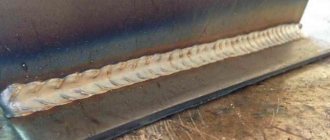
- Roller welding is a type of spot welding, but due to the special shape of the electrodes, presented in the form of two rollers through which current passes, the seam is solid. The surfaces are connected by the method of overlapping each other, therefore this type of welding is characterized by such types of defects as: lack of penetration (in case of insufficient current strength, clamping pressure or current supply of insufficient duration in time),
- insufficient overlap of the joint,
- splashes of metal (external and internal). Determining the cause, as well as the exact location, is difficult due to the overlap method.
It is complicated by inaccessible observation of the seam under the overlap, in which defects, as well as the exact location, become difficult to determine.
- Spot welding is a type of seam in which the entire seam is made in the form of points overlapping one another. Can be performed using electric arc, point, or welding methods.
In this case, the connection of two surfaces is carried out joint to joint. Detection of defects is simplified by having an open connection. Available visualization allows you to identify a bad weld that is causing the defect. This type of welding is characterized by the following types of defects:
How are fistulas in a weld seam corrected when they are identified? In most cases, this place is cut off and welded; if this approach is not possible, each product is examined on commission. The product may be repurposed for another, less critical use or rejected completely.
Ultrasonic flaw detection
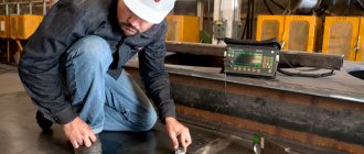
Ultrasound is used to control welding quality.
The operating principle of the device is based on the reflection of ultrasonic waves from the boundary between two media with different acoustic properties. The sensor and emitter are tightly applied to the material being tested, after which the device produces ultrasound. It passes through the entire metal and is reflected from the back wall, returning to the receiving sensor, which in turn converts ultrasound into electrical vibrations. The device presents the received signal in the form of an image of reflected waves.
If there are any flaws inside the metal, the sensor will record a distortion of the reflected wave. It has been experimentally established that various welding defects manifest themselves differently on an ultrasonic flaw detector. This made it possible to classify them. With appropriate training, a specialist can accurately determine the type of defect in a seam.
The method of ultrasonic quality control of welded joints has become widespread due to its simplicity and ease of use, relatively inexpensive equipment, and safety of use compared to the radiation method.
The disadvantage of this method is the difficulty of deciphering the graphic image. Connection quality control can only be done by a certified specialist. It is problematic to use it for testing coarse-grained metals such as cast iron.
Hydraulic weld test
It is carried out using water, which is supplied under pressure 1.5-2 times higher than the working pressure of the vessel. Within 10-15 minutes, the tightness of the seams is checked: fogging, moisture, etc.
Pneumatic seam test
The most environmentally friendly way. A defect such as a weld fistula can form during operation, in places where critical stress occurs in the metal structure, or due to pitting corrosion, as well as with a poor-quality welded joint. Pneumatic or vacuum testing. A soap solution is applied to one side of the seam, and a vacuum chamber is attached to the opposite side. If there is a crack, air enters the chamber, and the location of the leak is determined by the bubbles. Disadvantages include low productivity and technical unprofitability when testing large containers.
Pneumatic seam test
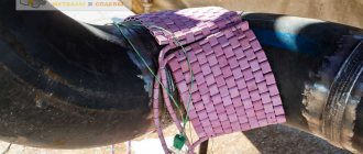
Checking welds with kerosene
How to test a weld for leaks with kerosene? This substance was not chosen by chance: it has high fluidity, several times more than water. In addition, checking welds with kerosene allows you to identify microscopic cracks and fistulas at home, without complex devices. It is carried out as follows: a chalk film is applied to the surface being tested, which should serve as an indicator, and kerosene is poured onto the reverse side.
Checking the tightness with kerosene
Checking the seam with ammonia
This type of check is also based on indicator readings. It is carried out using compressed air to which an ammonia solution is added. On the opposite side, apply paper or a clean medical bandage. The indicator substance is phenolphthalein, which is used to impregnate the material or 5% mercury nitrate. When ammonia comes into contact with the indicator, a reaction occurs that produces a purple color.
Testing a welded joint with a leak detector
The most complex method of all existing ones, but its use allows not only to determine the location of the leak, but also to determine its size by calculation. Three substances can act as a working medium:
- halide gas (freon-12);
- carbon dioxide;
- carbon tetrachloride;
- helium.
- A leak detector installation is used with a platinum heated probe installed in it and a milliammeter recorder. It is carried out as follows: a test vessel immersed in a container is subjected to double pressure. The working gas is supplied inside, and from the outside, on the contrary, the gas is sucked into a special gas. receiver with platinum probe. When gas ions appear, a reaction occurs with the ions located on the probe, which is recorded by an ammeter.
- Therefore, the second method, with helium, is based on the same principle of operation. Only when entering a vacuum environment, helium ions hitting the ion collector create an electrical discharge. In both cases, the size of the crack is calculated using a milliammeter.
- In the case of testing with carbon dioxide, the calculation is carried out on the principle of changing the heat transfer between heated platinum wires up to 100 ºС and CO molecules entering the chamber. The sensitive wire increases the resistance, which leads to imbalance and deviation of the measuring device.
Conclusion
Inspection of welded joints depends on the shape and size of the product. Methods can be roughly divided into 2 types:
- availability of both parties;
- one-way accessibility.
In addition, some available methods explain how to test a weld for leaks at home, without labor-intensive costs and specific instruments, such as checking a weld for leaks with kerosene.
Products go on sale in a tested condition, and for safe operation, each type of product has its own inspection and testing schedule, using the most convenient method for the owner.
Verification methods
Testing of welds for tightness is carried out in the following ways:
- kerosene;
- ammonia;
- pneumatic;
- hydraulic;
- vacuum.
Kerosene
The method is used to check the density of welded seams of vessels and tanks made of metal up to 10 mm thick, not operating under pressure.
The kerosene test is based on the phenomenon of capillarity. The essence of the method is the ability of kerosene to rise through through pores and cracks. Kerosene testing allows you to identify defects with a size of 0.1 mm.
The technology consists of coating the seam on one side with a solution of chalk or kaolin in water. After the chalk composition has dried, the seam on the reverse side is moistened several times with kerosene. If there are cracks, pores, or discontinuities, kerosene seeps through them and appears as spots on the chalk paint.
Kerosene test time:
- at temperatures above 0 °C - from 4 hours , critical products - 12 hours;
- at negative temperatures - from 8 hours , for serious objects - 24 hours.
Ammonia
The method is based on the property of a certain type of indicator (mercury nitrate solution or phenolphthalein) to change color as a result of exposure to liquefied ammonia. Used for testing closed welded vessels for density.
The process technique consists of covering the outside of the weld with strips of paper soaked in a 5% solution of silver nitrate. Compressed air containing 1% ammonia is pumped into the control vessel. Ammonia vapor passes through seam leaks and reacts with mercury nitrate, causing the paper to turn silver-black opposite the location of the defect. If phenolphthalein solution is used as an indicator, the color of the paper will be bright red.
The nature and size of the defect depend on the speed at which marks appear on the paper, their size and shape.
The penetration time of ammonia through weld leaks ranges from 10 minutes to half an hour.
Pneumatically
The method is intended for checking the tightness of the welded seam of products working under pressure. Compressed air is pumped into a small closed vessel, sealed with a plug, to a pressure 10-20% higher than the working one. The product is immersed in water. The presence of weld defects is determined by air bubbles escaping through the leaks.
Large items are sealed and the seams are coated with soapy water. Gas is supplied to the structure under test at a pressure exceeding the operating pressure by 10-20%. A sign of a defect is the appearance of bubbles on a seam moistened with a soap solution.
Large vessels and gas pipelines are checked for pressure drop. Due to their large length, the seams are not washed. The presence of defects is determined by the pressure drop over a period of 24 hours.
Pressure testing does not allow tapping of welds. The test is carried out in an isolated room. Carrying out inspections of large-sized products requires caution.
Hydraulic
Depending on the type of structure, there are 3 types of hydraulic tests:
- hydraulic pressure (hydraulic systems, pipelines);
- filling water (tanks, tanks, reservoirs);
- watering with a stream of water from one side (long products).
- Hydraulic pressure method . The object being tested is sealed and filled under pressure with working fluid or water. The type of liquid, its pressure and test time depend on the purpose of the control sample. The trial test pressure figure is indicated in the project. For pipelines it is 1.25 or more working pressure values. Test control is carried out at air temperatures above zero. The result is considered satisfactory if there is no fogging on the weld and no leakage is detected, and the gauge pressure has not dropped.
- Bulk control . The product is filled with water to a specified level. At air temperatures above 0° C, water temperatures above 5° C, holding time – up to 24 hours. Constant monitoring of the drop in water level and the condition of the welds is required. When defects are detected, the seam located on top is freed from water, the defects are eliminated, and water is added to test the newly welded section of the seam. The operations are repeated until all defects are completely eliminated.
- Watering with a stream of water . The test is carried out with a stream of water from a fire nozzle with an outlet opening of 15 mm. The speed of the jet directed along the seam is 1 m/min. The water pressure in the hose is at least 1 atm. The distance from the tip of the fire nozzle to the surface of the product is up to 2 m. The surface of the side of the test sample, opposite the one being watered, must be dry. Its inspection is carried out simultaneously with watering. Defective areas are manifested by the occurrence of leaks, the appearance of water drops, and fogging of the surface of the weld or heat-affected zone.
Vacuum
The method consists of isolating the test product from the external atmosphere by pumping out air and checking the vacuum. If there are defects in the welds, the vacuum will be broken.
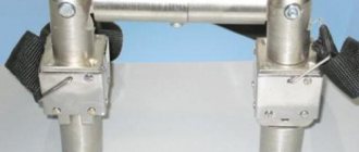
The method is suitable for monitoring the tightness of seams that are accessible only from one side - the bottoms of vertical tanks, gas tanks, waterproofing boxes, and the roofs of cylindrical oil tanks. The check is carried out using a vacuum device.
The camera of the device is installed on the joint of the seam, coated with an indicator - a soap solution - and the pump is turned on. Under the influence of atmospheric pressure, air passes through the leaks of the welded joint, and soap bubbles appear at the defects, which can be observed through the glass of the chamber. At low temperatures, sodium chloride (table salt) or calcium chloride is added to the foam indicator.
Source: elsvarkin.ru