GOST 2.312 - 72*
INTERSTATE STANDARD Unified system of design documentation
CONVENTIONAL IMAGES AND DESIGNATIONS OF WELDED JOINTS
Unified system for design documentation. Symbolic designs and representations of welds and welded joints
By Decree of the State Committee of Standards of the Council of Ministers of the USSR dated May 10, 1972 No. 935, the introduction date was set from 01/01/73
Instead of GOST 2.312-68
* Edition (March 2000) with Change No. 1, approved in July 1991 (IUS 10-91)
This standard establishes conventional images and designations of seams of welded joints in design documents of products from all industries, as well as in construction documentation that does not use images and designations used in construction.
IMAGE OF WELDED JOINTS
1.1. The seam of a welded joint, regardless of the welding method, is conventionally depicted:
visible - with a solid main line (Fig. 1a, c), invisible - with a dashed line (Fig. 1d).
A visible single weld point, regardless of the welding method, is conventionally depicted with a “+” sign (Fig. 1b), which is made with solid lines (Fig. 2).
Invisible single points are not depicted.
From the image of a seam or a single point, draw a line - a leader, ending with a one-sided arrow (see Fig. 1). It is preferable to draw the leader line from the image of the visible seam.
1.2. It is allowed to draw the contours of individual passes onto the image of the cross-section of a multi-pass weld, and they must be designated in capital letters of the Russian alphabet (Fig. 3).
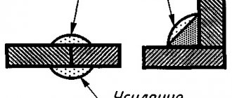
1.3. A seam, the dimensions of the structural elements of which are not established by the standards (non-standard seam), is depicted indicating the dimensions of the structural elements necessary to make the seam according to this drawing (Fig. 4).
The boundaries of the seam are shown as solid main lines, and the structural elements of the edges within the boundaries of the seam are shown as solid thin lines.
| Crap. 1 | Crap. 2 |
| Crap. 3 | Crap. 4 |
ANNEX 1
Recommended
mm
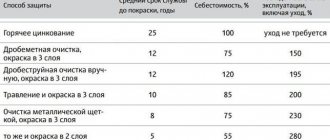
| Yield strength of welded steel, MPa | Minimum fillet weld leg for the thickness of the thicker element being welded | |||||||
| From 3 to 4 | St. 4 to 5 | St. 5 to 10 | St. 10 to 16 | St. 16 to 22 | St. 22 to 32 | St. 32 to 40 | From 40 to 80 | |
| Up to 400 | 3 | 4 | 5 | 6 | 7 | 8 | 9 | 10 |
| St. 400 to 450 | 4 | 5 | 6 | 7 | 8 | 9 | 10 | 12 |
Note. The minimum value of the leg should not exceed 1.2 times the thickness of the thinner element.
SYMBOLS FOR WELDED JOINTS
2.1. Auxiliary symbols for designating welds are given in the table.
| Auxiliary sign | Meaning of the auxiliary sign | The location of the auxiliary sign relative to the shelf of the line - a leader drawn from the image of the seam | |
| from the front side | from the reverse side | ||
| Remove seam reinforcement | |||
| Process sagging and unevenness of the seam with a smooth transition to the base metal | |||
| The seam should be made during installation of the product, i.e. when installing it according to the installation drawing at the place of use | |||
| Intermittent or spot seam with a chain arrangement Line angle » 60° | |||
| The seam is interrupted or dotted with a checkerboard arrangement | |||
| Seam along a closed line. Sign diameter - 3 ... 5 mm | |||
| Seam along an open line. The sign is used if the location of the seam is clear from the drawing | |||
Notes:
- The front side of a one-sided seam of a welded joint is taken to be the side from which welding is performed.
- The front side of a double-sided seam of a welded joint with asymmetrically prepared edges is taken to be the side from which the main seam is welded.
- Any side can be taken as the front side of a double-sided seam of a welded joint with symmetrically prepared edges.
In the symbol of a seam, auxiliary signs are made with solid thin lines. Auxiliary signs must be the same height as the numbers included in the seam designation.
2.2. The structure of the symbol for a standard seam or a single weld point is shown in the diagram (Fig. 5).
Crap. 5
The sign is made with solid thin lines. The height of the sign must be the same as the height of the numbers included in the seam designation.
2.3. The structure of the symbol for a non-standard seam or a single weld point is shown in the diagram (Fig. 6).
Crap. 6
The technical requirements of the drawing or table of seams indicate the welding method by which a non-standard seam should be made.
2.4. The symbol of the seam is applied:
a) on the shelf of the line - a leader drawn from the image of the seam on the front side (Fig. 7a); b) under the flange of the line - a leader drawn from the image of the seam on the reverse side (Fig. 7b).
Crap. 7
2.5. The designation of the roughness of the machined surface of the seam is applied on the flange or under the flange of the line - callouts after the symbol of the seam (Figure 8), or indicated in the table of seams, or given in the technical requirements of the drawing, for example: “Parameter of the surface roughness of welds...”
Note : The contents and dimensions of the seam table columns are not regulated by this standard.
Crap. 8
2.6, If a control complex or a seam control category is installed for the seam of a welded joint, then their designation may be placed under the leader line (Figure 9).
Crap. 9
In the technical requirements or the table of seams in the drawing, a link to the corresponding regulatory and technical document is provided.
2.7. Welding materials are indicated in the technical requirements drawing or seam table.
It is allowed not to specify welding materials.
2.8. If there are identical seams in the drawing, the designation is applied to one of the images, and lines are drawn from the images of the remaining identical seams - callouts with shelves. All identical seams are assigned one serial number, which is applied:
a) on a line - a leader that has a shelf with a seam marking (Fig. 10a);
b) on the shelf of the line - a leader drawn from the image of the seam, which does not have a designation, on the front side (Fig. 10b);
c) under the flange of the line - a leader drawn from the image of the seam, which does not have a designation, on the reverse side (Fig. 10c).
The number of identical seams can be indicated on a leader line that has a shelf with a marked designation (see Fig. 10a).
Crap. 10
Note : The seams are considered identical if:
- their types and cross-sectional dimensions of structural elements are the same;
- they are subject to the same technical requirements.
2.9. Examples of symbols for seams of welded joints are given in Appendices 1 and 2.
SIMPLIFICATION OF WELDED JOINT SEAM DESIGNATIONS
3.1. If there are welds in the drawing that are made according to the same standard, the designation of the standard is indicated in the technical requirements of the drawing (entry type: “Welds... according to...") or in the table.
3.2. It is allowed not to assign a serial number to identical seams if all the seams in the drawing are the same and are shown on the same side (front or back). In this case, seams that do not have a designation are marked with lines - callouts without shelves (Fig. 11).
Crap. eleven
3.3. In a drawing of a symmetrical product, if there is an axis of symmetry in the image, it is allowed to mark with lines - callouts and indicate seams only on one of the symmetrical parts of the image of the product.
3.4. In a drawing of a product in which there are identical components welded with identical seams, these seams can be marked with lines called callouts and indicated only in one of the images of the same parts (preferably in the image from which the line is given as a callout with the position number).
3.5. It is allowed not to mark the seams in the drawing with leader lines, but to provide welding instructions with an entry in the technical requirements of the drawing, if this entry unambiguously defines the welding locations, welding methods, types of seams of welded joints and the dimensions of their structural elements in cross section and the location of the seams.
3.6. The same requirements for all seams or a group of seams are given once - in the technical requirements or table of seams.
APPENDIX 1 Reference
EXAMPLES OF SYMBOLS FOR STANDARD WELDED JOINTS
| Seam characteristics | Seam cross-sectional shape | Symbol for the seam shown in the drawing | |
| from the front side | from the reverse side | ||
| A butt joint seam with a curved bevel of one edge, double-sided, performed by manual arc welding during installation of the product. Reinforcement has been removed on both sides. Roughness parameter of the weld surface: on the front side - Rz 20 µm; on the reverse side - Rz 80 µm | |||
| Fillet joint seam without bevel edges, double-sided, performed by automatic submerged arc welding along a closed line | |||
| Fillet joint weld with beveled edges, performed by electroslag welding with a wire electrode. Seam leg 22 mm | |||
| An overlapping spot weld made by arc welding in inert gases with a consumable electrode. The estimated diameter of the point is 9 mm. Step 100 mm. The location of the points is chessboard. The gain must be removed. The roughness parameter of the treated surface is Rz 40 µm. | |||
| A butt joint seam without beveled edges, one-sided, on the remaining backing, performed by welding with heated gas with a filler rod | |||
| Single lap joint welds made using submerged arc welding. The diameter of the electric rivet is 11 mm. The gain must be removed. The roughness parameter of the processed surface is Rz 80 µm. | — | ||
| T-joint seam without beveled edges, double-sided, intermittent with a staggered arrangement, performed by manual arc welding in inert gases with a non-consumable electrode with filler metal along a closed line. Seam leg 6 mm. The length of the welded area is 50 mm. Step 100 mm. | |||
| Single welded lap joints made by resistance spot welding. Estimated diameter of the cast core of the point is 5 mm | |||
| The lap joint seam is intermittent, performed by resistance seam welding. The width of the cast seam zone is 6 mm. The length of the welded area is 50 mm. Step 100 mm. | |||
| An overlap joint without beveled edges, one-sided, performed by semi-automatic arc welding in inert gases with a consumable electrode. Seam along an open line. Seam leg 5 mm. | |||
(Changed edition, Amendment No. 1).
GOST 14771-76
Topics: Welded joints.
State standard. Arc welding in shielding gas. Welded connections. Basic types, structural elements and dimensions. GOST 14771-76 *
Download the PDF collection of GOST for welding
Gas-shielded arc welding. Welded joints. Main types, design elements and dimensions
GOST 14771-76*
Moscow, 1991
STATE STANDARD OF THE USSR UNION
Valid from 07/01/77 to 07/01/92
1. This standard establishes the basic types, structural elements and dimensions of welded joints made of steels, as well as alloys on iron-nickel and nickel bases, performed by gas-shielded arc welding.
The standard does not establish the main types, structural elements and dimensions of welded joints of steel pipelines in accordance with GOST 16037-80.
2. The following designations of welding methods are accepted in the standard:
IN - in inert gases with a non-consumable electrode without filler metal;
INP - in inert gases with a non-consumable electrode with filler metal;
IP - in inert gases and their mixtures with carbon dioxide and oxygen with a consumable electrode;
UP - in carbon dioxide and its mixture with oxygen with a consumable electrode.
3. The main types of welded joints must correspond to those indicated in the table. 1.
Table 1
| Connection type | Shape of prepared edges | The nature of the seam made | Cross-sectional shape | Thickness of welded parts, mm, for welding methods | Symbol of welded joint | ||||
| prepared edges | completed seam | AND H | INp | IP | UP | ||||
| Styko-voe | With flange on two edges | Unilateral | 0,5 — 2,0 | — | O.5 - 4.0 | O.5 - 4.O | |||
| — | 0.8 - 4.O | 1.O - 12.O | 1.O - 12.O | S28 | |||||
| With flange on one edge | 0,5 — 2,0 | — | O.5 - 4.0 | O.5 - 4.O | |||||
| No beveled edges | 0,5 — 4,0 | O.8 - 6.O | 0,8 — 6,0 | O.8 - 6.O | |||||
| Single-sided with removable lining | 0,8 — 8,0 | ||||||||
| Single sided with remaining lining | 0,5-4,0 | O.8 - 6.O | 0,8 — 6,0 | O.8 - 8.O | |||||
| Single-sided locking | |||||||||
| Bilateral | 3.O - 6.O | 3.O - 6.O | 3.O - 6.O | 3.O - 12.O | |||||
| With one edge beveled | Unilateral | — | 3.0 - 10.O | 3.O - 10.O | 3.O - 60.O | ||||
| Single-sided with removable gasket | |||||||||
| Single sided on remaining gasket | C10 | ||||||||
| Single-sided locking | — | 3 — 10 | 3 - 1O | 3 — 40 | C11 | ||||
| Bilateral | — | 3 — 60 | C12 | ||||||
| With a curved bevel of one edge | — | — | 18 - 1OO | 18 - 1OO | C13 | ||||
| With a broken bevel of one edge | — | — | C14 | ||||||
| With two symmetrical bevels on one edge | — | 6 — 20 | 8 - 1OO | 8 — 100 | C15 | ||||
| With two symmetrical curved bevels on one edge | Bilateral | — | — | 30 — 120 | 30 — 120 | C16 | |||
| With two beveled edges | Unilateral | — | 3 — 10 | 3 - 1O | 3 — 60 | C17 | |||
| Single-sided with removable lining | C18 | ||||||||
| Single sided with remaining lining | — | C19 | |||||||
| Single-sided locking | — | S20 | |||||||
| Bilateral | S21 | ||||||||
| With stepped bevel of two edges | Unilateral | — | 4 — 20 | 4 — 20 | — | C22 | |||
| With a curved bevel of two edges | Bilateral | — | — | 24 — 100 | 24 — 100 | C23 | |||
| With a broken bevel of two edges | — | — | 24 — 100 | 24 — 100 | C24 | ||||
| With two symmetrical bevels on two edges | — | 6 — 20 | 6 - 12O | 6 — 120 | S25 | ||||
| With two symmetrical curved bevels on two edges | — | — | 26.0 - 120.O | 26,0 — 120,0 | C26 | ||||
| With two symmetrical broken bevels on two edges | — | — | — | S27 | |||||
| Angular | With flange on one edge | Unilateral | 0,5 — 3,0 | O.5 - 3.O | 0,5 — 4.0 | O.5 - 4.O | |||
| — | 0.8 - 4.O | 1.O - 12.O | 1,0 — 12,0 | y2 | |||||
| No beveled edges | — | 0,8 — 4.0 | O.8 - 8.O | O.8 - 8.O | |||||
| — | 0,8 — 10,0 | O.8 - 10.O | 0,8 — 30,0 | ||||||
| Double-sided | 0,8 — 4,0 | O.8 - 12.O | O.8 - 12.O | ||||||
| 0.8 — 10,0 | O.8 - 30.O | 0,8 — 30,0 | |||||||
| With bevel on one edge | Unilateral | — | 3.0 - 10.O | 3.O - 10.O | 3.O - 60.O | ||||
| Bilateral | — | 3 — 10 | 3 - 1O | 6 — 60 | |||||
| With two symmetrical with bevels of one edge | — | 6 — 20 | 6 - 2O | 6 — 100 | |||||
| With two beveled edges | Unilateral | — | 3 — 20 | 3 - 2O | 3 — 60 | ||||
| Bilateral | — | U10 | |||||||
| Tavrovoe | Without beveled edges | Unilateral | — | 0,8 — 40,0 | O.8 - 40.O | O.8 - 4O.O | |||
| Without beveled edges | Bilateral | — | 0,8 — 40,0 | O.8 - 4O.O | O.8 - 4O.O | ||||
| With one edge beveled | Unilateral | 3 — 10 | 3 - 6O | 3 — 60 | |||||
| Bilateral | |||||||||
| With two symmetrical bevels on one edge | Bilateral | — | 6 — 20 | 6 — | 6 — 80 | ||||
| — | — | 12 - 1OO | 12 - 1OO | ||||||
| Overlap-accurate | Without beveled edges | Unilateral | 0,8 — 4,0 | O.8 - 10.O | O.8 - 6O.O | O.8 - 6O.O | |||
| Bilateral | 0,8 — 4.0 | O.8 - 1O.O | 0,8 — 60,0 | O.8 - 6O.O | |||||
4. Structural elements of welded joints, their dimensions and maximum deviations for them must correspond to those indicated in the table. 2-47. In addition to the specified welding methods, it is allowed to use other methods of arc welding in shielding gases.
Continued - page 2 >>>
Quick navigation through GOST 14771-76 tables:
01) Table 2 Symbol of welded joint C1, open in a new window >>>,
02) Table 3 Symbol of welded joint C28, open in a new window >>>,
03) Table 4 Symbol of welded joint C3, open in a new window >>>
04) Table 5 Symbol of welded joint C2, open in a new window >>>,
05) Table 6 Symbol of welded joint C4, open in a new window >>>,
06) Table 7 Symbol of welded joint C5, open in a new window >>>,
07) Table 8 Symbol of welded joint C6, open in a new window >>>,
08) Table 9 Symbol of welded joint C7, open in a new window >>>,
09) Table 10 Symbol of welded joint C8, open in a new window >>>,
10) Table 11 Symbol of welded joint C9, open in a new window >>>,
11) Table 12 Symbol of welded joint C10, open in a new window >>>,
12) Table 13 Symbol of welded joint C11, open in a new window >>>,
13) Table 14 Symbol of welded joint C12, open in a new window >>>,
14) Table 15 Symbol of welded joint C13, open in a new window >>>,
15) Table 16 Symbol of welded joint C14, open in a new window >>>,
16) Table 17 Symbol of welded joint C15, open in a new window >>>,
17) Table 18 Symbol of welded joint C16, open in a new window >>>,
18) Table 19 Symbol of welded joint C17, open in a new window >>>,
19) Table 20 Symbol of welded joint C18, open in a new window >>>,
20) Table 21 Symbol of welded joint C19, open in a new window >>>,
21) Table 22 Symbol of welded joint C20, open in a new window >>>,
22) Table 23 Symbol of welded joint C21, open in a new window >>>,
23) Table 24 Symbol of welded joint C22, open in a new window >>>,
24) Table 25 Symbol of welded joint C23, open in a new window >>>,
25) Table 26 Symbol of welded joint C24, open in a new window >>>,
26) Table 27 Symbol of welded joint C25, open in a new window >>>,
27) Table 28 Symbol of welded joint C26, open in a new window >>>,
28) Table 29 Symbol of welded joint C27, open in a new window >>>,
29) Table 30 Symbol of welded joint U1, open in a new window >>>,
30) Table 31 Symbol of welded joint U2, open in a new window >>>,
31) Table 32 Symbol of welded joint U4 (0.8 - 30 mm), open in a new window >>>,
32) Table 33 Symbol of welded joint U4 (0.8 - 8 mm) open in a new window >>>,
33) Table 34 Symbol of welded joint U5 (0.8 - 12 mm), open in a new window >>>,
34) Table 35 Symbol of welded joint U5 (0.8 - 30 mm), open in a new window >>>,
35) Table 36 Symbol of welded joint U6 (2-30 mm), open in a new window >>>,
36) Table 37 Symbol of welded joint U7, open in a new window >>>,
37) Table 38 Symbol of welded joint U8, open in a new window >>>,
38) Table 39 Symbol of welded joint U9, open in a new window >>>,
39) Table 40 Symbol of welded joint U10 open in a new window >>>,
40) Table 41 Symbol of welded joint T1, T3, open in a new window >>>,
41) Table 42 Designation of welded joint T6, open in a new window >>>,
42) Table 43 Symbol of welded joint T7, open in a new window >>>,
43) Table 44 Symbol of welded joint T8, open in a new window >>>,
44) Table 45 Symbol of welded joint T9, open in a new window >>>,
45) Table 46 Symbol of welded joint H1, open in a new window >>>,
46) Table 47 Symbol of welded joint H2, open in a new window >>>,
47) Table 48 Thicknesses of thin parts and thickness differences, open in a new window >>>,
INFORMATION DATA
1. DEVELOPED AND INTRODUCED by the research and production association TsNIITMASH.
PERFORMERS
M. M. Borisenko (topic leader); V. D. Khodakov; E. G. Starchenko.
2. APPROVED AND ENTERED INTO EFFECT by Resolution of the State Committee of Standards of the Council of Ministers of the USSR dated July 28, 1976 N1826.
3. The inspection period is 1990. The inspection frequency is 5 years.
4. The standard corresponds to TGL 14905/03 regarding the form and content of tables of welded joints.
5. INSTEAD GOST 14771-69.
6. REFERENCED REGULATIVE AND TECHNICAL DOCUMENTS.
7. REISSUE with Amendments No. 1, 2, 3, approved in March 1982, December 1986, January 1989.
STATE STANDARD OF THE USSR UNION
WELDING, SOLDERING AND THERMAL CUTTING OF METALS
PART 3
Other pages on the topic “GOST 14771-76”:
01) Defects in welded joints,
02) Ultrasonic testing of welded joints,
- < GOST for welding
- GOST 5264-80 Manual arc welding. Welded connections. Main types, structural elements and dimensions >