Results and discussion
Combustion of metals, their alloys, metal-containing substances, incl. Organometallic substances according to GOST 27331-87 are divided into 3 classes:
- class D1 – combustion of light metals (aluminum, magnesium and their alloys, calcium, titanium), conventionally “heavy” metals (zirconium, niobium, uranium, etc.);
- class D2 – combustion of alkali metals (lithium, sodium, potassium, etc.);
- class D3 – (organometallic compounds: aluminium, lithium, organozinc, hydrides of aluminum, lithium, etc.).
Each of the listed metals and their hydrides is a solid in its normal state, except for organometallic compounds (MOCs), which are liquids.
Of the features of metals that are directly related to their fire, explosion and combustion hazards, the following should be noted:
- tendency to spontaneous combustion under normal conditions (i.e. pyrophoricity);
- the ability to explode in a state of air suspension;
- interaction of burning metals with water, some gaseous fire extinguishing compounds: freons (chlorofluorocarbons), nitrogen (for example, magnesium), etc.
Alkali metals, shavings, metal powders with a non-oxidized active surface, metal hydrides, MOS (fire classes D2, D3) have the ability to spontaneously ignite.
The most flammable and explosive metals, the combustion of which occurs in class D1, are light metals in the form of their processing products: powders of different dispersion, shavings. It is almost impossible to ignite metals in the form of products of various configurations (sheets, profiles, etc.) if the conditions for the predominance of heat removal over heat gain are ensured.
Metal hydrides occupy an intermediate position between metals and organic compounds. This is due to the fact that during their decomposition hydrogen is released, which can be considered as an analogy to the process of release of flammable gases during the pyrolysis of organic materials burning in the gas phase [1]
.
At the same time, metal hydrides differ significantly from each other in their physical and chemical properties, in the mechanism of combustion and ignition. Thus, hydrides of titanium, niobium, tantalum, etc. are essentially solutions of hydrogen in metal and have a variable composition with a metallic type of bond. They burn mainly in a smoldering mode; there is practically no flaming combustion of hydrogen.
At the same time, lithium aluminum hydride (LAH), aluminum hydrides (HA) and lithium hydrides (HL) are pronounced individual compounds with ionic (for GL - partially covalent) bonds, characterized by the presence of flame and heterogeneous combustion modes [2]
.
HA and alkali metal hydrides exhibit pyrophoric properties, actively interact with air moisture, with slight heating they actively release hydrogen and, as a result, form hybrid explosive mixtures with air in the state of air suspension.
At elevated temperatures and during combustion, nitrogen can interact with the most active hydrides, for example, HA.
A slight dilution of nitrogen with air can lead to a very “hard” explosion of the HA air suspension, so not all metal hydrides can use nitrogen as a protective atmosphere. Sometimes you have to use argon for this.
Thus, the nature of the combustion of metals and metal-containing substances excludes the use of water, water-foam extinguishing agents and a number of gas fire extinguishing compounds, since when these agents come into contact with burning metals, they interact, leading to combustion.
In Russia and world practice, special-purpose fire extinguishing powder compositions (OPSN) are used to extinguish fires of classes D1, D2, D3. When creating the formulation of such compositions, the following factors are taken into account:
- the main substance that determines this composition (from 80 to 95% vol.) should not contain an oxygen atom in the molecule (not support combustion) and not enter into a chemical reaction with the metal;
- OPSN must have a certain fractional composition (usually in the range of 50-75 microns);
- SPSN should not cake during storage, which is achieved by including anti-caking, water-repellent additives in their composition, and also have a number of other performance properties in accordance with generally accepted technical requirements;
Currently, the most common for extinguishing fires of classes D1, D2, D3 are fire protection equipment based on alkali metal chlorides (KCl - Russia and NaCl - Europe, USA). There are a number of liquid compositions (for example, based on boron ethers) as fire extinguishing compositions for metals, but they have not found widespread use in fire extinguishing practice.
The main principle of achieving a positive result when extinguishing metal-containing substances (according to classes D1, D2, D3) is the creation, with the help of fire protection equipment, of a protective complete covering of the combustion area, preventing the access of air oxygen to the combustion zone. Such a coating must be sufficiently dense and have the required thickness of the powder layer over the entire surface of the combustion site, which is achieved at a certain specific powder consumption (kg/m2).
Extinguishing metals and metal-containing substances has a number of features inherent in each group of substances in classes D1, D2, D3, including:
- to extinguish metals according to class D1, fire protection equipment must meet the criteria given above, while the powder is based on, for example, potassium chloride with a density of about 1 g/cm3);
- for extinguishing metal hydrides (D3), OPSN is used with characteristics similar to OPSN used for extinguishing class D1;
- for organometallic substances that are liquids under normal conditions, OPSN should have a density close to the density of these substances (~ 0.7-0.8 g/cm3), which is ensured by the introduction of a low-density non-flammable additive into the powder composition (perlite, vermiculite) , which also promotes the adsorption of MOC and improves the reliability of extinguishing.
When extinguishing sodium [3]
The so-called “capillary” or wick combustion effect occurs due to the growth of oxide formations growing through the layer of powder, through which liquid sodium penetrates and burns in the form of a wick. To prevent the growth of oxides, special additives are usually used.
Extinguishing metals and metal-containing compounds of fire-fighting equipment is fundamentally different from extinguishing, for example, hydrocarbon flammable liquids, gas liquids (fire classes A, B, C) with general-purpose powders. In the case of extinguishing fires of class D (D1, D2, D3), the main task when supplying fire protection equipment is to create a layer of powder coating on the surface of the combustion site, preferably equal in height, which is achieved by using so-called dampers attached to the supply device (at the outlet of the supply barrel ) fire extinguishers, powder vehicles. The use of a dampening nozzle when supplying fire extinguishing equipment is necessary when extinguishing metal powders and their hydrides, while the formation of an aerosol suspension of fire extinguishing powder is practically prevented. To extinguish fires of classes A, B, C, a “pistol” type spray device is used, which creates a powder cloud over the combustion source, which helps to achieve extinguishing.
OPSN can be used to extinguish radioactive metals. When using, for example, a fire extinguishing agent based on potassium chloride, the release of radioactive aerosols is significantly reduced.
However, the use of powder fire extinguishing also has its disadvantages:
- The fire extinguishing powder composition, unlike water, does not have a cooling effect. Reliable extinguishing can be achieved by cooling metals to a temperature below their auto-ignition temperature. And the temperature of burning metals, as a rule, is significantly higher than the self-ignition temperature, so the process of extinguishing metals and their hydrides is lengthy;
- Almost all powder extinguishing vehicles produced have limited technical capabilities and cannot provide reliable extinguishing in rooms with a volume of more than 300-600 m3. The maximum height for supplying fire extinguishing equipment, depending on the type of powder extinguishing vehicle and the pressure in the tank, is 10-25 m, while the maximum distance for supplying powder horizontally is 40-60 m, which in some cases is insufficient to ensure delivery of the powder to the site sunbathing
The melting point of the metal must be higher than its ignition temperature in oxygen.
(For St. 3, the melting point is -1539°C,
and the ignition temperature is 1100-1200°C.)
Carbon significantly reduces the melting point. Therefore, it is impossible to cut high-carbon steels and cast irons with a conventional cutter.
The melting point of the metal must be higher than the melting point of its oxides.
Otherwise, a film of oxides will prevent access
there will be no oxygen to the metal and no combustion (cutting). (Chromium oxide has
the melting point is 2270°C, and the melting point for St. 3 is -1539°C).
The oxides formed during cutting must be sufficiently fluid.
If there is an excess of them, they stick to the edges of the cut, and it is very difficult to remove them.
difficult (Oxides of silicon, chromium, etc. have high viscosity).
The metal must be a poor conductor of heat, otherwise the heat from the flame will not be enough to heat the edge before cutting begins.
Oxygen cutting technology
The oxyfuel cutting process is shown in the figure below.
The metal being cut is preheated by the preheating flame of the cutter, which is formed as a result of the combustion of flammable gas mixed with oxygen. When the ignition temperature of the metal in oxygen is reached, the pure oxygen valve on the cutter opens (99–99.8%) and the cutting process begins. Pure oxygen from the central channel of the mouthpiece, intended to oxidize the metal being cut and remove oxides, is called cutting, in contrast to the oxygen of the heating flame, which comes mixed with flammable gas from the side channels of the mouthpiece.
A jet of cutting oxygen displaces molten oxides into the cut, which, in turn, heat the next layer of metal, promoting its intense oxidation, etc. As a result, the cut sheet undergoes oxidation throughout its entire thickness, and molten oxides are removed from the cutting zone under the influence of the cutting jet. oxygen.
The cutting quality is affected by:
- oxygen consumption
Lack of oxygen leads to incomplete oxidation
metal and non-intensive removal of oxides; and excess leads to cooling and removal of heat from the cutting zone.
- oxygen purity
Reduced cleanliness affects the quality of cut edges;
The lower the cleanliness, the more difficult-to-remove slag adheres to the lower edge of the cut.
— power of the heating flame;
Look at the summary!!!
4. Electrical safety requirements when performing electric and gas welding work.
Ticket number 5
1. Preparing metal for welding. Before welding, after selecting the metal according to the size and grade of steel, it is necessary to perform the following operations: • straightening; • cutting; • edge processing and cleaning for welding. Edges are prepared by thermal and mechanical methods. Depending on the thickness of the metal being welded, it can be welded either without cutting edges or with cutting. Cutting metal edges starts from 5 mm. There are certain geometric parameters for cutting edges (Fig. 13). Be sure to make a gap during the welding process b
to melt metal through its entire thickness.
Its dimensions are 0.5-5 mm, depending on the thickness of the metal being welded. Blunting the edges is
necessary to form the root of the weld, and in order not to melt through the thin metal. Its dimensions are 2-2.5 mm.
Rice. 13. Preparing metal for welding
β - edge bevel angle (15-45°); S is the thickness of the metal.
The cutting of edges can be different depending on the thickness of the metal (Fig. 14). Look at the summary!!!!
Rice. 14. Examples of edge preparation: I - flange height; R—radius of curves; β is the bevel angle of the edges; α is the cutting angle; S and S1 - metal thickness
2. Welding torches (purpose, classification, design, marking, preparation for work, safety requirements). The welding torch is used to mix flammable gas or flammable liquid vapor with oxygen and produce a welding flame. Welding torches are divided as follows: • according to the method of supplying combustible gas and oxygen to the mixing chamber - injection and non-injector; • by the type of combustible gas used - acetylene, for substitute gases, for liquid combustibles and hydrogen; • by purpose - universal (welding, cutting, soldering, surfacing) and specialized (performing one operation). An injection burner (Fig. 15) is a burner in which the supply of combustible gas to the mixing chamber is carried out due to its suction by a stream of oxygen flowing at high speed from the nozzle opening. This process of sucking gas of lower pressure with a stream of oxygen supplied at a higher pressure is called injection, and burners of this type are called injection burners.
Rice. 15. Design of an injection welding torch: 1 - mouthpiece; 2 — replaceable tip; 3 - mixing chamber; 4 — injector nozzle; 5 - oxygen valve; 6 — oxygen nipple; 7 - acetylene valve; 8 - acetylene nipple
For normal operation of injection burners, it is necessary that the oxygen pressure be 0.15-0.5 MPa, and the acetylene pressure is much lower - 0.001-0.12 MPa. Its operating principle is as follows. Oxygen from the cylinder under operating pressure through the nipple, tube and valve 5 enters the injector nozzle 4. Coming out of the injector nozzle at high speed, oxygen creates a vacuum in the acetylene channel, as a result of which acetylene, passing through nipple 6, tube and valve 7, is sucked in into mixing chamber 3. In this chamber, oxygen, mixing with flammable gas, forms a flammable mixture. The flammable mixture, exiting through the mouthpiece 1, is ignited and, burning, forms a welding flame. The supply of gases to the burner is regulated by oxygen valve 5 and acetylene valve 7, located on the burner body. Replaceable tips 2 are connected to the burner body with a union nut. A non-injector burner is a burner in which combustible gas and heating oxygen are supplied at approximately the same pressure of 0.05-0.1 MPa. They do not have an injector, which is replaced by a simple mixing nozzle that is screwed into the burner tip tube. Rules for handling burners: 1. Operating faulty burners is not allowed, as this can lead to explosions and fires, as well as burns to the gas welder. 2. A working torch produces a normal and stable welding flame. 3. To check the burner injector, connect the hose from the oxygen reducer to the oxygen nipple, and the tip to the burner body. The tip is tightened with a wrench, the acetylene valve is opened and the required oxygen pressure is set using the oxygen reducer according to the tip number. Let oxygen into the burner by opening the oxygen valve. Oxygen passing through the injector creates a vacuum in the acetylene channels and acetylene nipple, which can be detected by placing a finger on the acetylene nipple. If there is a vacuum, the finger will stick to the nipple. If there is no vacuum, it is necessary to close the oxygen valve, unscrew the tip, unscrew the injector and check whether its hole is clogged. If it becomes clogged, it must be cleaned, and the holes in the mixing chamber and mouthpiece must also be checked. After making sure that they are in good working order, repeat the suction (vacuum) test. 4. The amount of suction depends on the gap between the end of the injector and the entrance to the mixing chamber. If the gap is small, then the vacuum in the acetylene channels will be insufficient; in this case, the injector should be slightly unscrewed from the mixing chamber. 5. First, open the oxygen valve of the burner slightly, thereby creating a vacuum in the acetylene channels. Then open the acetylene valve and ignite the combustible mixture. 6. The flame is regulated with an acetylene valve with the oxygen valve fully open. 7. When there is a pop, first close the acetylene and then the oxygen valves. 8. Causes of popping noises: • severe overheating of the burner; • clogging of the burner mouthpiece; • if the flow rate of the combustible mixture becomes less than the speed of its combustion, the flame will penetrate into the mouthpiece channel and a back blow will occur. 9. In this case, the burner must be extinguished, cooled with water and the mouthpiece cleaned with a needle.
3. Semi-automatic welding machines (purpose, classification, design, safety requirements)
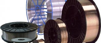
In mechanized welding, special welding machines are used that provide mechanized supply of welding wire, and the movement of the arc along the axis of the seam is done manually. Such devices are called semi-automatic arc welding machines. Semi-automatic machines are classified according to different criteria: • according to the method of protecting the welding zone - for submerged arc welding, gas-shielded welding, open arc; • according to the method of arc regulation - semi-automatic devices with self-regulation of the arc are mainly used; • by type of wire used - solid, flux-cored or combined; • according to the wire feeding method - pushing, pulling and combined type; • according to design - with stationary, mobile and portable feeding device. For welding, semi-automatic machines are produced, designed for rated currents of 150-600 A, for wire with a diameter of 0.8-3.5 mm with feed speeds of 1.0-17.0 m/min. The set of semi-automatic machines usually includes: • a feeding device with cassettes for electrode wire; • control cabinet; • welding torches; • wires for welding circuit and control circuits; • gas equipment. Design and main components of semi-automatic devices. In mechanized welding, the welding head is most often divided into two parts - a feed mechanism and a holder (for gas-shielded welding - a welding torch), connected to each other by a flexible hose. Therefore, such devices are sometimes called hose devices. Semi-automatic welding machines allow you to combine the advantages of automatic welding with the versatility and maneuverability of manual welding. A typical semiautomatic circuit diagram is shown in Fig. 54. They include the following components: holder 1, flexible hose 2, welding wire feeder 3, welding wire cassette 4 and a hardware cabinet or control cabinet 5. The most critical element of semi-automatic devices is the wire feeder
. Its purpose and layout are approximately the same as those of the welding heads of arc welding machines. Typically it consists of an electric motor, a gearbox and a system of feed and pressure rollers. The mechanism ensures the supply of electrode wire through a flexible hose into the welding zone.
Rice. 54. Scheme of a semi-automatic arc welding machine
The drive can be AC or DC motors. In the first case, the feed speeds are changed by step-changeable gears, in the second - smooth regulation occurs by changing the engine speed. The design of the feed mechanism largely depends on the purpose of the semi-automatic device. In semi-automatic machines for welding with large-diameter wire, the feed mechanism is placed on a mobile trolley and is located in a separate housing. In semi-automatic machines with small diameter wire, it is installed in a portable case and located directly on the holder body. The most widespread are push-type
.
The feeder feeds the wire by pushing it through a flexible hose to the torch. In this case, stable feeding is possible if the electrode wire is sufficiently rigid. In pull-type
, the feed mechanism or its feed rollers are located in the burner. In this case, the wire is pulled through the hose. This system ensures a stable supply of soft and thin wire. There are semi-automatic machines with two synchronously operating feed mechanisms that simultaneously push and pull the wire through the hose (pull-pull type). The flexible hose in semi-automatic machines is designed to supply electrode wire, welding current, shielding gas, and sometimes cooling water to the torch. For this purpose, a specially designed hose wire is used. Welding torches are designed to supply electrode wire, welding current and shielding gas or flux to the welding site, as well as to manually move and manipulate it during the welding process. In this case, the welder holds the holder in his hand and moves it along the seam. The quickly wearing parts of the holder (when welding in shielding gases - torches) are the current-carrying tip and the gas nozzle, made of copper. For submerged arc welding, a flux hopper is installed on the holder (Fig. 55). The semi-automatic machine uses drives operating on both alternating and direct current.
Rice. 55. Semiautomatic holder for submerged arc welding: 1 - tip; 2 - hopper for flux; 3 - welding wire; 4 - handle; 5 - hose
Maintenance of semi-automatic arc welding machines. To ensure uninterrupted and long-term operation of semi-automatic devices, as well as to timely eliminate minor faults during their operation, it is necessary to carry out preventive maintenance. Every day before starting work you should: • check the condition of the mouthpiece tip and gas nozzle. If contaminated, remove splashes and carbon deposits, restore reliable contact; • check the place where the mouthpiece is attached to the hose cable; • check the fastening of the welding torch to the hose cable, inspect the insulation of the wires; • test the operation of the semi-automatic device by trially turning on the starting plug. At least once a month: • check the condition of the feed mechanism rollers; • check the lubricant level in the feed mechanism gearbox and top up if necessary; • clean the channel through which the electrode wire is fed from accumulated dirt.
Literature:
- Chibisov A.L., Soina E.A., Gabrielyan S.G., Smirnova T.M., Gabrielyan G.S. Limiting conditions and features of ignition, combustion and extinguishing of various metals // Hydrogen materials science and chemistry of metal hydrides: Collection of abstracts of the VII international conference. - Ukraine, Yalta, 2001. - P. 416.
- Chibisov A.L., Smirnova T.M., Gromov A.D., Akinin N.I. Determination of the safe specific rate of hydrogen evolution in a technological process // Hydrogen materials science and chemistry of metal hydrides: Collection of abstracts of the VIII international conference. - Ukraine, Yalta, 2003. P.356-357.
- Gabrielyan S. G., Gabrielyan G. S. Recommendations for quenching liquid sodium and pyrophoric organoaluminum catalysts M.: Izd. VNIIPO, 2000, 19 p.
Other related articles:
- Basic suspension and steering problems - part 1
- Safety precautions and basic safety requirements during disassembly
- Sharpening and straightening cutting tools
- Basic suspension and steering problems - part 2
- Main elements of the ignition system. Ignition coil. Part 2
- Main elements of the ignition system. Ignition coil. Part 1
- Safety precautions when operating washing equipment and using detergents
- Workplace. Features of the organization and safety
- Safety precautions when using benzene and antifreeze
- Safety precautions when working on the line
