I will give examples of all the designed components of metal structures that I design in all my projects, from simple to complex. This means you can get acquainted with the connection options for all the main structures of buildings: columns, racks, beams, trusses, purlins. I studied each type at its infancy stage, which means I made manual calculations. That is why I confidently use them in my working drawings and include them in reports upon request. A hasty approach to connections, firstly, significantly increases the consumption of rolled metal by 5% or more, and secondly, it loses aesthetics. Some serial variants are, as a rule, with a small margin.
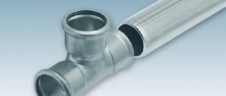
Assemblies of metal beams, columns, trusses, and frames
All the main connections between them can be used at the factory, and they are also made during the development of the product itself in industry. Thanks to this, it will be possible to significantly increase the overall length of all products. Moreover, such units from metal beams can be manufactured as an assembly option. Then production will be carried out on the construction site itself. With their help, it will be possible to connect separate components, combining them into one whole structure. Such connection work will cost a little more than the total cost of factory work. In this case, the same mounting bolts are required, and they are made to special order and only in accordance with the beams.
What beams do manufacturers produce and where are they used?
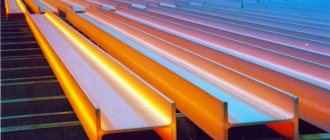
Beams can be welded or hot rolled. Hot-rolled ones are considered the most popular. Thanks to their monolithic nature, they are highly durable and reliable. Manufacturers produce several types of such rolled products with a length from 4 to 15 m:
- The most common is normal (indicated by the letter “B”). They are used for the construction of buildings, bridges, overpasses, and are used in machine and carriage building.
- Wide-shelf (indicated by the letter “Ш”) has wider shelves compared to normal ones. It is used in metal structures operating under high loads.
- Columned (indicated by the letter “K”) is characterized by an increased thickness of the wall and shelves. It is used when installing supporting structures or columns.
- Pile (indicated by the letter “C”) can have parallel or angled shelves. This type of rolled metal is most often used for reinforcing mines.
- Special rolled metal products manufactured to individual orders are designated by the letters “DB” or “DK”.
Interfaces with special columns made of steel material
A structure supported by beams on columns can be made in the form of a hinged or rigid fastening. But still, if possible, the beams should be supported on top and the entire load should be applied only in the central part of the column profile frame.
Side mounting
When fastening from the side, in addition to compressive loading, a main moment arises in the entire frame when, due to the action of this force, a so-called eccentricity appears, causing the frame to receive a large load, thus leading to excessive consumption of the metal frame of the column.
In order for this load to be transmitted correctly and only through each rib, then it is necessary to ensure that the ribs protrude slightly from their level, usually this can be from 15 to 20 millimeters. This same rib will have to be planed a little so that the total load can then be transferred to the entire area of the rib.
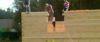
The process of supporting two beams from the top of the columns
In the same way as in the previous one you need to:
- support them over the edge and bring them to the head of the columns;
- here they need to be connected, aligned with each other and secured with bolts;
- It is better not to fasten the bolts from the top, unless you need to make a rigid knot;
- you will have to install the appropriate plates between them so that you don’t have to tighten them together again later.
In addition, you can support two beams at once on one column head using the following design
In this connecting part, the main role is played by the beam located on the bottom flange at the very top of each column.
- In order to transmit the entire lateral force, it will have to be reinforced with an edge.
- We further fasten the rib so that during the installation process it ends up above the column flange itself.
- Next, they need to be connected with bolts, as well as with the help of special overhead plates (make sure that the entire load is located symmetrically).
- Here, too, there is no need to connect all the beams from the top so that a knot does not form.
- In this case, ribs on the columns are not required.
- It is best to leave a small opening between them, 10 or 20 mm in size.
Hinged mounts on columns from the side
For any side mounting, you need to calculate all the columns and create the so-called eccentricity. When supported using hinged fasteners, the load will be transmitted only through the support rib and only to the support table. A small table is usually made from durable sheet steel material, but it is not equal angle. The height of the table can be determined by ensuring that each weld is firmly installed. Here you need to weld the table on three main sides. The total width of this table will have to be made taking into account 20 - 40 mm, slightly larger than the size of the beam rib.
The total diameter of all holes is 3 or 4 mm larger than the diametric parameters of each bolt, but only so that it cannot hang on the bolts, but rather can lie perfectly on this table.
When using a hinged frame, supporting the ribs into the frame column is not required. Between this rib, which serves as a support, and also the column, a metal gasket is mounted, the thickness of which should not exceed 5 mm.
Pairing with columns in a rigid version (welding)
It will be possible to make a rigid connecting part only using bolts, but also by welding. Still, the bolted connection option is considered more technologically advanced. Since in this case almost all parts are developed and also painted in production. When building a frame, you just have to install them and tighten the bolts more tightly.
Several steel spacers will have to be installed between the supporting ribs, as well as the columns, so that the beams and columns fit snugly against each other. That is, in this case there should be no gap between them.
The maximum number of bolts required will have to be calculated only according to the torque that arises.
Table of dimensional characteristics of column and wide-flange I-beams
| Range of characteristics | I-beams | |
| Wide shelf | Columned | |
| Wall height, mm | 193-718 | 196-431 |
| Shelf width, mm | 150-320 | 199-400 |
| Wall thickness, mm | 6,0-23,0 | 6,5-23,0 |
| Shelf thickness, mm | 9,0-36,5 | 10-33,5 |
| Weight 1 m, kg | 30,6-305,9 | 41,3-290,8 |
| Number of meters per ton | 3,27-32,7 | 3,44-24,21 |
Production technology
In the typical version, an I-beam is made from three sheet blanks: a wall and two flanges, welded to its ends at right angles. Manufacturing is carried out on specialized assembly lines configured to produce beams of a certain size.
The workpieces are moved on special rollers and pre-fixed in the desired position by clamping devices equipped with a hydraulic or pneumatic drive.
On the section of the assembled beam fixed by the clamping device, tacks are made by welding along the waist seam. After this, the beam moves along the rollers, is secured again, and its next section is tacked by welding.
The waist seam is finally welded after the entire structure is pre-fastened with welded tacks.
Welding of T-joints between the wall and the flanges is carried out automatically under a layer of flux. The automatic welding process can be performed with different devices. These can be welding manipulators, the torches of which weld, moving along given trajectories through articulated joints with several degrees of freedom.
Simpler devices such as self-propelled welding tractors, which are much more suitable for creating straight connections, can also be used.
Another class of devices capable of automatically welding waist seams of I-beams is cantilever or portal installations. In addition to the welding equipment itself, they include equipment for monitoring and quality control of the weld, as well as devices for supplying flux and subsequent cleaning of the seam from its residues.
Such installations carry out welding at an optimal angle of 45 °, which ensures the most favorable location of the weld pool and, accordingly, high quality of the weld.
Intense heating of the workpieces during the welding process leads to warping of the shelves. For this reason, the process of assembling I-beams includes a procedure for leveling them, carried out on special machines to correct the mushroom shape.
At the final stage of manufacturing, the ends of the product are milled.
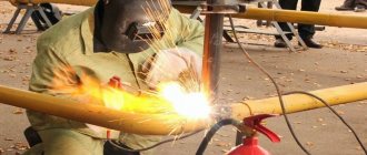
How to weld I-beams
Steel beams with an I-beam cross-section are designed for universal use in mechanical engineering and construction. When studying the nature of stresses arising in loaded products having a solid cross-section, the unevenness of their distribution was revealed.
Sections of the cross-section of parts with the highest stress values were identified. As a result of this, the idea arose of creating a product with a cross-sectional shape where the mass of metal is concentrated in the most loaded areas. This is how the I-section appeared.
Application of I-beams for the manufacture of centrally compressed columns
The functional purpose of such columns is to transfer loads acting from above to the base of the structure, and through it to the soil. These structural elements are subject to pressure from longitudinal forces, resulting in uniform compression of the cross section.
Structural components of centrally compressed columns:
- Header. Designed for fixing structures located above it.
- Kernel. Main load-bearing element.
- I-beam column base. Attached to the base with anchor bolts. Serves to distribute the applied force over the surface of the foundation.
I-beam columns, based on the cross-section of the rod, are divided into through (lattice) and solid. The height of the section can be constant in size or variable. When calculating the optimal column design, the following are taken into account:
- the amount of force applied;
- operating conditions;
- manufacturing capabilities;
- convenience of joining elements that provide additional support for the structure.
Replacement with channels
In practice, when constructing building structures, welding channels to each other is sometimes used to obtain an I-section.
If channels are used instead of I-beams provided for in the design, such replacement must be approved. Agreement on the use of alternative material is reflected by changes made to the relevant sections of the detailed design. The possibility of replacement is determined based on the results of strength verification calculations performed by designers.
The method used to weld the channels together is also determined by calculation. This can be welding with a continuous or intermittent seam, or using connecting pads.
When welding channels with a continuous seam, as a result of thermal deformations of the metal, twisting of the profile may occur. This phenomenon can be avoided by using special clamps, as well as by applying welding seams in small sections, alternating the sides of the profiles being connected.
If it is necessary to lengthen such a structure, the channels are butt welded. The locations of the butt welds of the channels forming the I-beam should not coincide with each other. To strengthen the structure, the weld can be reinforced with a pad.
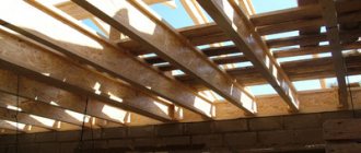
Additional functions of an I-beam in private housing construction
The floor itself does not necessarily have to consist only of metal I-beams. Often they are used only in the most intense places, and wooden I-beams are installed between the metal parts.
Why is that? The fact is that welding requires highly qualified workers. Further, in ordinary literature and Internet sites there is not that variety of components and ready-made design diagrams for installing such a ceiling; a competent engineer is really required here, and even we only give recommendations. In addition, metal is not cheap. And the quality of welding is very important. It must work for a long time, even under conditions of corrosion or changing loads.
Therefore, this option not only has the right to life, but is also quite practical:
And finally, a metal I-beam often serves as an additional functional element, which has value in any household:
source