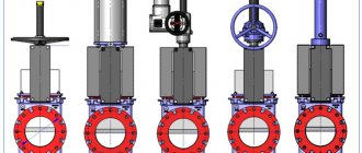
Christmas tree fittings
When laying pipelines and performing similar types of various works that take place in various areas where drilling operations are required, it is often necessary to use additional elements such as Christmas tree fittings.
Application of Christmas tree fittings
The fountain fittings have the following purposes. With its help, one or more pipelines are connected, controlling processes take place and the flow of the medium in the well is controlled. Also, with the help of Christmas tree fittings, sealing work is carried out on the well and branches are carried out for the flow line. Thus, the use of this equipment is of great importance and affects the productivity of all pipeline laying work.
As a rule, the use of Christmas tree fittings is necessary in certain conditions, for example, when under heavy loads that are created under excess pressure. Or in cases where the well may be exposed to aggressive substances such as hydrogen sulfide, mineral water or carbon dioxide.
Often the use of fountain fittings occurs under strong abrasive loads, when water is mixed in large quantities with fractions of different rocks
When using fountain fittings, it is important to take into account that this auxiliary equipment must have very high strength characteristics and durability. The main types of work in which this equipment is used are laying oil pipelines and gas production
Characteristics of Christmas tree fittings
Since the conditions in which Christmas tree fittings can be used may have different loads, GOST provides for several types of Christmas tree fittings.
The design of the fountain fittings includes such elements as a pipe-type piping and a fountain tree. Pipe piping directly connects one or more pipelines. Carries out control and control functions over the environment in the well and the space between the well pipes. The fountain tree directly controls the well flow itself and directs the flow to the places of field operations. The tree is located on a piping system.
Christmas tree fittings have a design feature that allows them to protect and prevent any entry of pipeline contents into the soil and thereby performs an environmentally protective function. The set of fountain fittings certainly includes all kinds of shut-off devices, and such replaceable equipment as chokes. The design of the fountain fittings also includes such a part as a pipe head.
Features of the design of Christmas tree fittings
This part serves so that several rows of compressor-pump type pipes can be suspended from it. This fastening ensures free access to the space behind the pipe. The fountain fittings can have a tee or cross type. Each of these types has a number of advantages. Thus, a tee-type Christmas tree makes it possible to carry out repair work on a well without stopping its operation.
But since this design of the Xmas tree is asymmetrical, there is a possibility of a large overturning moment. Cross reinforcement has such positive qualities as compactness and a sufficiently high level of stability, since its design is symmetrical. But the disadvantage of this type of fittings is that repairs here are not feasible in the operating mode of the well.
promplace.ru
Fountain type fittings
Today there is such a type of fittings as wellhead fountain. It, in turn, is divided into several types. It can be a tee type or a cross type. The choice depends on which fountain tree was chosen. It can also be either double-row or single-row. This is determined by the number of pumping tubular products that will be lowered down into the well. The equipment can be taps or valves, that is, it differs in the type of locking device. The difference between this type of fittings is that the through hole can be from 50 to 150 mm. Used at pressures from 14 to 140 MPa.
Basic parameters of the device
Equipment for the production of foam blocks: technologies for preparing the mixture, methods for molding products.
required equipment The main defining characteristic for wellhead equipment was size. The average length of such a device is about three meters. As for the width, it naturally varies depending on the model, but the approximate average is 715 millimeters. The last indicator in terms of dimensions is the height, which is on average 1.5 meters.
Another important indicator for this equipment is the passage of the locking device. The numerical value of this parameter can reach up to 50 millimeters. Along with wellhead fittings, equipment such as pumping and compressor equipment is also used for the well. The pipe diameter of such devices can reach up to 75 mm. It is worth noting that this type of fitting is not a specific device, but a set of several important components that perform purposes such as sealing the wellhead. In addition, the fittings will be responsible for distributing the flow of substances that will come from the well. You can also regulate such a volatile substance as gas, for example.
Features of the device
It is worth highlighting one very important advantage of this type of fittings. If any element fails during operation, it can be replaced without taking the entire station out of service. This is one of the most important criteria, since in this case it becomes possible to carry out repair work without disrupting the time interval of the station’s operation. This is one of the main requirements in the oil production environment. In addition, this helps to save a significant amount of material resources that would have been lost while the station was idle for repairs.
The structure itself is tied together using a variety of clamps and different flanges. It is also worth highlighting here that if in the entire structure any element has a deviation from the nominal data, then all other devices belonging to the locking type and all other mechanical elements will be disabled. An automatic system is responsible for this, which is equipped with any fittings of this type.
Principles of proper arrangement
- Around the mouth the soil must be compacted or a layer of concrete must be poured.
- The upper part of the trunk is sealed taking into account the geodetic features of the area.
- The caisson must be insulated.
- Installation of the head and sealing are carried out immediately after drilling the shaft and pumping it.
- Pumping equipment is installed as close to the wellhead as possible.
- The source is connected taking into account its flow rate.
Linear bearings
Wellhead piping is the installation of equipment to supply water to the surface through the inlet of the mine shaft. The pump, submerged in the casing or mounted on the surface, is connected to a hose passing through the head cover.
To install a caisson, you will need to prepare a strong and reliable foundation. The soil is dug up around the mine and ASG is poured. Concrete is poured onto a well-compacted base in a layer of up to 10 centimeters. Such a foundation will support both a plastic caisson and a brick box. External walls must be treated with waterproofing materials. They are insulated inside.
Design and device
Forge shop: description, equipment. cold forging
The design of the wellhead valve includes such necessary working elements as a pipe-type head, a column-type head, and the valve itself, which is a control and shut-off valve. These fittings include elements such as valves, all kinds of valves and crane-type parts.
The immediate purpose of this type of device is to contain the heavy flow of pressure and examine the pressure inside the structure itself. This design is also intended to create injection or to bleed gas flows.
As a rule, the wellhead assembly is driven by a mechanical drive, but in cases where the pressure in this device is very high, containment can be achieved through either a hydraulic system or a pneumatic installation.
The entire structure has a connection, which is carried out through the use of special fastening elements such as clamps and various flanges. If a sudden deviation from the nominal data occurs, all shut-off devices and mechanisms stop working and are locked by means of an automatic control system equipped with the wellhead valve.
Equipment design
When it comes to the design of this device, there are several main components. These include, for example, a pipe-type head, a column-type head and a head of the valve itself. The valve head is of the adjustable-shut-off type. Even such small devices as valves, gate valves and some other small parts of this kind can be distinguished as components.
The main purpose of wellhead fittings is to contain a strong flow of pressure, as well as the ability to study this pressure inside the structure itself. To operate this type of valve, a mechanical drive is usually used. However, it happens that the pressure is too high. In this case, it will be restrained either using pneumatic type installations or using a hydraulic system. It is also worth saying that there may be wellhead injection valves. In this case, it is capable of performing the functions of injection or release of gas flows.
Design
The production of fittings, according to GOST 13846-84, involves the use of tee and cross type schemes.
The device consists of:
data-ad-client=»ca-pub-8514915293567855″ data-ad-slot=»1955705077″>
- pipe head;
- fountain tree;
- manually operated locking devices;
- chokes.
The pipe head is used to hang several rows of tubing and seal them. In addition, the pipe head takes part in technological operations, which include: development, operation and repair of the well.
Hanging of columns is carried out (on a thread):
- if a single-row elevator - on the coil thread;
- if there is a two-row elevator: the inner column is on the thread of the coil, the outer column is on the thread of the crosspiece of the pipe head.
The pipe head requires replacement of its side valves. This process is carried out using special blind plugs, which are installed in the threaded holes of the housing.
Shut-off devices on fountain fittings with manual control
Christmas tree functions:
- directs product to the flow line;
- takes part in the installation of special devices;
- measurements of pressure and temperature of the environment;
- lowering downhole instruments for pipe cleaning.
Shut-off devices are presented in the form of straight-through plug valves and direct-flow valves with a lubricant supply. Their main purpose is to cover passage holes.
Column heads serve as casing hanger, sealing and pressure control between pipe strings. to menu
Technical requirements for design
GOST 13846-89 defines a Christmas tree as a device designed to seal wells, shut off the medium and direct it to the manifold, and carry out other technological operations.
According to GOST 16350-80, fountain fittings can be used in temperate and cold macroclimatic regions. Placement is carried out according to category 1 (GOST 15150-69).
Optimal ambient temperature: from -60ºC to +40ºC.
High-quality fittings are durable and can withstand atmospheric loads
GOST 51365-2009 established the use of a certain material and the level of technical requirements that are most suitable for operating conditions.
The production of parts can be designed according to individual orders, taking into account that all operating conditions and the choice of component materials will comply with established standards. to menu
Designation AFK
- AF – fountain fittings;
- K – method of hanging the pipeline according to GOST 13846-84;
- n – scheme according to GOST 13846-84 (n = 1-6);
- E – cable entry;
- 65×21 – nominal diameter and working pressure in MPa;
- HL – climatic versions of the product;
- K1 – corrosion resistance category.
Typical schemes according to GOST 13846-89:
- AF1, AFK 1;
- AF2, AFK 2;
- AF3, AFK 3;
- AF4, AFK 4;
- AF5, AFK 5;
- AF6, AFK 6.
to menu
Installation and dismantling of fountain fittings
During the use of the well, the structure is installed and pressure tested. The main function in connection is performed by column heads. The holes located in the upper flange allow you to attach parts of various sizes.
Installation of an equipment unit made from Christmas tree fittings
Step-by-step installation:
- Special low-carbon steel with an oval cross-section is placed between the flanges.
- Using elevators, a string of compressor pipes is lowered.
- The pipes are screwed together (before screwing, the threads of the pipes must be lubricated).
- Pipe columns are lowered.
Upon completion of installation, a pressure test is performed to check the tightness of all connections.
Structural repairs take place in specialized workshops. Previously, the fountain fittings are disassembled into individual parts. The tree is thoroughly washed and other components are checked.
Christmas tree fittings have a design feature that allows you to protect the soil and the environment from the contents of the pipeline. to menu
TYPICAL DIAGRAMS AND MAIN PARAMETERS
1.1. Typical diagrams of fountain trees must correspond to those shown in Fig. 1, injection trees - to hell. 2.
1.2. Typical piping diagrams for Christmas tree and injection valves must correspond to those shown in Fig. 3.
1.3. Typical diagrams of wellhead fittings should be compiled by a combination of standard diagrams of wellhead trees with piping.
Typical diagrams of fountain trees
1
- adapter to the pipe head;
2
- tee;
3
- locking device;
4
— pressure gauge with shut-off and discharge device;
5
- throttle;
6
— counter flange;
7
— cross
Crap. 1
Typical diagrams of injection trees
1 —
adapter to the pipe head;
2
- tee;
3 -
locking device;
4 —
pressure gauge with shut-off and discharge device;
5 -
check valve;
6
— counter flange;
7
— cross
Crap. 2
Typical Xmas tree piping diagrams
injection valves
1 —
counter flange;
2
- locking device;
3 -
pipe head;
4 —
pressure gauge with shut-off and discharge device;
5
- quick connection
Crap. 3
Examples of typical diagrams of fountain fixtures are shown in Fig. 4, injection valves - to hell. 5.
1
- fountain tree (Fig. 1);
2 -
piping (Fig. 3)
Crap. 4
1
— injection tree (Fig. 2);
2 -
piping (Fig. 3)
Crap. 5
1.4. The main parameters of the Christmas tree fixtures must correspond to those indicated in the table. 1.
Table 1
| Conditional bore, mm | Working pressure, MPa | ||
| tree trunk | side branches of the tree | side outlets of the pipe head | |
| 50 | 50 | 50 | 14, 21, 35, 70, 105 |
| 65 | 50, 65 | 50, 65 | |
| 80 | 50, 65, 80 | 14, 21, 35, 70, 105, 140 | |
| 100 | 65, 80, 100 | ||
| 150 | 100 | 21 | |
1.5. The main parameters of injection valves must correspond to those indicated in the table. 2.
table 2
| Conditional bore, mm | Working pressure, MPa | ||
| tree trunk | side branches of the tree | side outlets with head tube | |
| 50 | 50 | 50 | 14, 21, 35 |
| 65 | 50, 65 | 50, 65 | |
| 80 | 65, 80 | 21, 35 | |
1.6. Symbols of wellhead trees and fittings must consist of a name, a code constructed according to the scheme in Appendix 1, and a designation of a regulatory and technical document for supply.
Examples of symbols
Christmas tree with suspension of the well pipeline in the pipe head, with a Christmas tree according to standard scheme 6, with automatic control, with a nominal bore of 80 mm and side branches of 65 mm, for a working pressure of 70 MPa:
Christmas tree fittings AF6A-80/65´70 GOST 13846-89
Trees with a well pipeline suspended in a sub to a pipe head (reel-pipe holder), made according to standard scheme 2, with manual control, with a nominal bore of 65 mm, side branches of 50 mm, for a working pressure of 35 MPa, corrosion-resistant design K2:
Christmas tree EFK2-65/50´35K2 GOST 13846-89
Injection fittings with suspension of the well pipeline in a sub to the pipe head, made according to standard scheme 1, with manual control, with a nominal diameter of the trunk and side branches of 65 mm, for a working pressure of 21 MPa:
Injection fittings ANK1-65´21 GOST 13846-89
The same, with two pipe heads according to the devil. 4b:
Injection fittings ANK1a-65´21 GOST 13846-89
Injection tree with the same parameters and purpose:
Injection tree ENK1-65´21 GOST 13846-89
Equipment for fountain wells
Flowing wells can be equipped with equipment both at the bottom and at the mouth. If the rocks in the area of productive formations are of high strength, then open-hole technology can be used, when the column reaches the top of the formation, and opening is carried out at full capacity. In unstable rocks and a high risk of sand shedding, the bottomhole area should be strengthened with casing and the space outside it should be cemented. In this case, the influx of liquid is created by perforating along the lower edge of the pipe.
The flowing well design involves sealing the wellhead, which is done by installing a column head and a reinforcement structure equipped with a manifold. The creation of reinforcement is carried out according to the requirements of GOST 13846-89, and the design may differ in strength and type of structure. The basis is the head, or trim, and the fountain tree includes shut-off devices and elements for regulating the operation of the well. The head in the design is necessary for tying pipelines in the well, as well as for adjusting the direction and force of flow in the annular zone.
Structurally, the fittings for a fountain well allow you to measure pressure indicators on the upper segment of the tree, identify the temperature regime on the side branches of the tree and the head itself. According to the GOST standard, the design must include block elements and devices for protecting the structure, which, if necessary, can be activated from a distance. The fountain tree is an important part of the overall design, and it allows you to regulate the flow force in the pipeline itself and direct it into the production channel.
Equipment with a pair of tubing pipes, products of larger diameter are placed on the lower part using a threaded connection to an element that simultaneously serves to seal the space behind the pipes. If the well should not be stopped during operation, it makes sense to install a two-section tree, which ends at the top with a special buffer and a pressure gauge. When lowering into a functioning fountain well, these devices are replaced by a lubricator. Design types are selected based on the characteristics of the well and the characteristics of oil production in a particular field.
Using devices
Wellhead fittings are used not only for working with an oil pipeline. It can also be successfully used to conduct deep research, for example. Another option for using it is to adjust the fluid intake. All these examples quite clearly show that the use of wellhead equipment is an integral part of oil production.
It is important to add that the selection of such devices is carried out according to special criteria, and all of them are distinguished by the fact that the quality of their production is very high, as is their productivity. For example, the operating temperature range at which wellhead equipment is able to perfectly perform its functions is in the region from -60 to +40 degrees Celsius
In other words, they can be used in almost any climate.
The meaning of fountain pipes
Even with the same amount of gas content in the formation, not every well is capable of flowing. For example, if the volume of such gas is sufficient to ensure flowing in a well of 150 mm in diameter, then it may not be enough for a diameter of 200 mm.
The gas-oil mixture that moves along the wellbore looks like a layer-by-layer alternation of oil and gas layers. Therefore, the larger the diameter of the production pipe string, the greater the amount of gas required to lift the oil liquid through it.
Read also: How to properly use a thermometer for petroleum products?
In practice, there have been cases in which wells with large bore diameters (from 150 to 300 millimeters), which were drilled to a depth with highly productive formations with high internal pressure, were distinguished by high flow rates, but even in them, flowing most often continued to be quite a short time. Moreover, in some cases, wells drilled into productive formations with high pressures cannot flow out under normal conditions.
In this regard, in order to make the most efficient use of the energy of the expanding gas, all mine workings where blowouts are possible are equipped before development with lift pipes, the nominal diameters of which vary from 60 to 114 millimeters. It is through these small-diameter pipes that the gas-liquid mixture moves in the drilled well.
The selection of the diameter of lifting (elevator) pipes occurs, as a rule, experimentally, and depends on the following factors of a specific mine working:
- expected well flow rate;
- reservoir pressure value;
- drilling depth;
- specific operating conditions.
During the process of well flowing through a small-diameter pipe string, the gas factor decreases, which makes it possible to extend the flowing time period. In many cases, a well flowing through a pipe string with a diameter of 73, 89 or 114 millimeters first began a regime of periodic emissions, and then it stopped completely. In such cases, the duration of the fountain was extended by replacing these pipe columns with fountain pipes of smaller diameters (33, 42, 48 and 60 millimeters).
Brief information
GBU RT "Social Assistance Center of Kyzyl" was registered on July 7, 2003 by the registrar INTERDISTRICT INSPECTION OF THE FEDERAL TAX SERVICE No. 1 FOR THE REPUBLIC OF TUVA. Head of the organization: director Saryglar Orlanmaa Belek-Oolovna. The legal address of the State Budgetary Institution of the Republic of Tajikistan “Social Assistance Center of Kyzyl” is 667011, Republic of Tyva, Kyzyl city, Bai-Khaakskaya street, building 6.
The main type of activity is “Other care activities with provision of accommodation”. The organization STATE BUDGETARY INSTITUTION OF THE REPUBLIC OF TUVA “CENTER FOR SOCIAL ASSISTANCE FOR FAMILY AND CHILDREN OF KYZYL CITY” was assigned TIN 1526939068, OGRN 3181933751031, OKPO 12923612.
Flowing Well Study
The flowing well design requires regular studies, which are carried out using the method of test pumping of liquid and the method of restoring pressure in the bottom hole after the equipment is stopped. Specialists adjust the operating mode by changing fittings and installing elements with holes of different sizes. The test pumping method can be successfully used to identify the degree of productivity of a well and determine the optimal mode of its operation. As for the method of restoring the pressure level, it can be used to calculate the main characteristics of the formation.
The procedure for selecting liquid for research is carried out using special devices that are fixed and lowered like a pressure gauge. Lowering the pressure gauge itself requires a lubricator in the design, which will be equipped with an oil seal with a roller. The gland acts as a sealing agent for the hole through which the wire is passed. If it is necessary to carry out deep research, it is necessary to use a mechanical lifting winch, which is placed 20-30 meters from the mouth.
First, the template is lowered down, then the measuring device (sometimes with a weight). To prevent the wire from breaking during the study, the equipment must not be lowered below the edge of the pipe. To prevent this phenomenon, the shoe is equipped with a special pin that limits the descent inside the column. The lifting is carried out at low speed; in the last meters it should be minimal (in some cases, research devices are pulled out manually).
The flow rate is measured in group installations, and a tap is used for sampling, which takes a sample of the liquid and gives the result after some time.
Wellhead, Wellhead Equipment
IA Neftegaz.RU
. Wellhead - The connection between the casing and the blowout preventer or christmas tree bolted or welded to the guide pipe or conductor. The wellhead is located on the surface of the earth and represents the beginning of the depression, and the bottom is called the bottom.
Purpose of the mouth:
- protective - prevents the collapse of loose soils;
- collective - is the exit point of the well components;
- regulating - controlling the pressure inside the well system.
Wellhead equipment is a set of equipment designed for tying casing strings, sealing the wellhead (annulus, internal cavity of the tubing, draining well products) during the drilling process, overhauling wells and regulating the operating mode of the well during its operation.
The composition of wellhead equipment used in piping the wellhead during well drilling includes:
- column head,
- blowout prevention equipment.
Column head The column head, with the help of which casing strings are tied during the drilling process, also serves as the basis for installing the Xmas tree. It remains on the well for the entire period of operation. Casing head functions:
- connection of casing structures and other wellhead equipment,
- sealing the space;
- maintaining the mass of the technical column;
- holding the production string.
The connection of the next casing string link is provided by fittings that are attached to the casing head. Installation of casing pipes is carried out using adapters and regulators.
The production wellhead equipment also includes:
- fountain fittings,
- Christmas tree manifold,
- device for replacing valves under pressure,
- lubricator used in well testing,
- a set of valves, subs and other parts necessary for installation and piping of wellhead equipment.
Christmas tree fittings
Christmas tree fittings are a system of mechanisms and devices that perform regulating and controlling functions. The fountain fittings provide:
- sealing the mouth of a flowing well,
- suspension of elevator columns,
- flow control and management.
Composition of the fountain fittings:
- column head - connected to the casing;
- pipe head - connected to the elevator columns;
- fountain tree - distribution and regulation of products.
Equipment requirements:
- ability to withstand high pressure;
- possibility of carrying out pressure measurements;
- ensure the release or injection of gas;
- possibility of hanging casing columns,
- possibility of sealing.
Christmas tree diagrams:
- manometric;
- valve;
- tee;
- throttle
Flanges and clamps are used to connect valve components. The pipeline is connected through a manifold.
CONDITIONAL SIZES OF CONNECTING FLANGES FOR MOUTHOUT AND DISCHARGE FITTINGS
| Conditional bore, mm | Working pressure, MPa | Conditional bore, mm | |
| top flange of the pipe head | pipe head bottom flange | ||
| 50, 65, 80 | 14 | 180 | 180*, 280 |
| 21, 35 | 280 | ||
| 50, 65 | 70, 105 | ||
| 80 | 70, 105, 140 | ||
| 100 | 14, 21, 35, 70, 105, 140 | 230 | |
| 150 | 21 | 280 | 350 |
* Less preferred conditional passage.
DESIGNATION OF CORROSION-RESISTANT FITTINGS AND TREES
| Designation | Well environment - oil and gas with volumetric content |
| K1 | CO2 up to 6% |
| K2 | CO2 and H2S up to 6% |
| K3 | CO2 and H2S up to 25% |
INFORMATION DATA
1. DEVELOPED AND INTRODUCED by the Ministry of Chemical and Petroleum Engineering of the USSR
PERFORMERS
R.D. Dzhabarov,
Ph.D.
tech. sciences; A.G.
Dozortsev, Ph.D.
tech. Sciences (topic leader); T.K.
Veliyev, Ph.D.
tech. Sciences (topic leader); CM.
Osipova; L.G. Sharonova 2. APPROVED AND ENTERED INTO EFFECT by Resolution of the USSR State Committee on Standards dated February 24, 1989 No. 332
3. The verification period is 10/01/93.
The inspection frequency is 5 years.
4. The standard fully complies with ST SEV 4354-83
5. INSTEAD GOST 13846-84
EXAMPLE OF A TYPICAL DIAGRAM OF A CHOWT FIXTURE WITH A CONTROL SYSTEM
1
— control station;
2
— sub to the pipe head;
3
— counter flange;
4 -
pipe head;
5
- manually operated locking device;
6 —
pressure gauge with shut-off and discharge device;
7
— locking device with remote control;
8 —
cross;
9
- adjustable throttle;
10 —
air pilot (automatic safety device)
Note. The diagram does not show sensors for pressure, temperature, gas contamination, etc.
Wellhead equipment
The casing pipe is made of metal, plastic or polyethylene. Depending on the material used, the head is installed using different technologies. A flange is welded to the steel casing. The counter is attached to it, on which all the equipment will be located. The lid must be solid. A thread and a distribution unit are mounted in the upper part if a station is used and not a submersible pump. A pipe or water supply hose is threaded through the lid.
The head for a polyethylene or plastic pipe is practically no different from a steel one. The same flanges and bolts, but the gasket between the connections is rubber, not paronite. In the factory version, the head cover has holes with a collet clamp for a hose or pipe, which is immersed in the shaft. The cable entry is carried out through a pipe with a rubber seal. For ease of installation and repair, hooks are attached to the flange on both sides.
What does the fittings consist of?
This building material contains a number of different structural components. The head contains a column-type flange, a cross, as well as a tee and a transfer spool. The tree serves to control and remove the products obtained from the well from the well.
You can disassemble the design of the fountain fittings element by element to understand the purpose of the most important components.
- Column flange
- serves to connect the fittings to the column and ensure the tightness of the space behind the pipe - Head cross
- to allow communication with the space behind the pipe - Tee
- the pipe row is suspended and connected to it - Transfer coil
– suspension of the secondary row of pipes - The fountain tree cross makes it possible to divert products received from the well into the central pipeline
- A buffer valve
is a kind of window designed to allow the lowering of various types of deep measuring equipment into a well. - Buffer pipe
- a certain transition zone before lowering the devices into the well, which is located in front of the buffer valve
The main condition for all components of the fountain fittings is their good tightness and strength.
. If necessary, all elements must be quickly replaced so as not to create long downtime in the operation of the well. As shut-off devices, it is allowed to use such types as direct-flow valves, various types of taps, and corner valves.
It is also possible to use two types of Christmas tree equipment
.
Fittings based on the use of tees are recommended for use in wells with low and medium pressure, as well as when there are various types of mechanical impurities in the well.
If there are impurities, it is necessary to use double tree fittings. If there is no well with medium and low pressure, it is possible to use a single-string tree. Xmas trees based on crosses are used in high-pressure wells without mechanical impurities.
The disadvantage of fittings made using crosspieces is that if one of the outlet units fails, it becomes necessary to completely stop the operation of the well while the malfunction is eliminated
.
When operating a well on tees, this need is eliminated; it is enough to shut off the middle part of the outlet unit and switch the work to the lower outlet device.
Devices for injection wells
The main purpose of this type of fittings is to seal injection wells. A special feature is that all work can be carried out while water is being pumped into the well. The main parts of the equipment include the pipe head and the tree. The first element is used to seal the annulus. It is also necessary to perform certain repair work, research work, and some technological operations. This element consists of components such as latches, a cross and several elements for quick connection.