When constructing buildings, any building structures need to be given serious attention. Floors are no exception. These structures take the load from equipment, people, furniture, and the floors themselves and transfer them to columns or walls. Floors can be attic, interfloor, basement and basement. Metal channels are often used for their construction.
In this article we will look at what to consider when choosing them and which channel to use for floors.
Metal ceiling between floors with channel
To install durable floors in buildings being constructed, builders use proven methods that involve the use of various building materials. An increased margin of safety is provided by profiles made of rolled steel. Floors constructed on their basis on metal beams ensure the reliability of the structures being erected and a long service life. They are superior to structures based on wooden beams in terms of performance and are able to withstand significant loads. Let's look at them in detail.
Selection of cross-section and checking for channel rigidity
Using the reference book (see GOST 8240-97 or GOST 8278-83), we select a channel profile that has a moment of resistance greater than the design one. In this case, a 27P channel is suitable, Wx = 310 cm3, Ix = 4180 cm4. Next, it is necessary to check the strength and bending rigidity of the channel (deflection of the whip).
Test of strength:
- σ = Мр/(γ∙Wx)∙1000 = 60∙1000/(1∙310) = 193 MPa Source
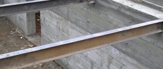
When creating or expanding openings of various types - windows, doors, their high-quality strengthening is important. Installing a channel is the most popular way to strengthen such structures. It is widely used for load-bearing structures made of reinforced concrete and brick. As soon as the steel frame is installed, the entire load, which was previously taken by the remote parts of the partitions, is transferred to the channel.
Such reinforcement has a positive effect on the structure: it is protected from destruction and cracking. The height of the channel edges is from 5 to 40 mm - this is expressed by the number on the marking. A distinctive characteristic of the product is its U-shaped format. Metal products have resistance to bending and compression, and can withstand significant loads of building elements. They give any metal structure additional stability and reliability. Products are manufactured in accordance with GOST
8240-89
.
How are openings strengthened with channels?
To create a metal frame, accurate measurement results and a carefully made opening are required. If these conditions are met successfully, then the channel is fastened quickly, easily, comfortably - there is no dust, dirt, or unnecessary noise. Another bonus is that the interior partitions remain intact. Here is a brief example of work on decorating an opening with a metal profile:
- Before cutting the opening, specialists install safety racks, which will strengthen the structure and take the load from it during the installation period;
- the boundaries of the future opening are marked;
- next - dismantling the wall elements;
- After this, the opening is strengthened with a steel beam.
Structural options for flooring on metal beams
Based on a steel profile, you can make a durable floor using various options:
- The ceiling is monolithic on metal beams. It is formed by pouring concrete into the formwork, and is additionally reinforced with reinforcing mesh. This is a practice-tested option with a range of advantages. The main advantages that attract developers are the increased strength of the seamless surface and the absence of irregularities;
- monolithic prefabricated structure. For its arrangement, blocks of cellular concrete manufactured at industrial enterprises are used. They are laid with their edges on the surface of the steel profile. Thermally insulated formwork is constructed, reinforcement is made and the joint areas are filled with concrete mortar;
- composite structure made of various materials. Standard panels, wooden boards, and slabs can be used. The base elements are installed on load-bearing steel beams. To ensure comfortable operating conditions, it is important to insulate and soundproof the formed surface, as well as seal the gaps between the elements.
Depending on financial capabilities and availability of materials, developers equally use these options.
Particularly stringent requirements are imposed on the quality and strength of floors in a building of any design.
Monolithic ceiling device
Profiled sheets, reinforcement and concrete are the components that form a monolithic concrete floor slab. This design, if supported by a beam frame, distributes the load onto the columns rather than the walls. Each column has its own foundation. Another option is when the cross beams are not laid or, if installed, rest on the walls.
In this case, the monolithic floor will have to load the walls of the structure and the foundation. Metal beams - I-beam (channel). Their edges are strengthened in the “pockets” of the walls (columns) and welded to the mortgages. Sheets can be attached to beams on the internal shelf, then the distance between the supports for short sheets is chosen to be no more than 1.5 m. On channels/I-beams, profiled material can also be installed on the external shelf on top so that sheets up to 6 m long can be placed .
They are installed overlapping along the length. A stationary beam is placed under the middle of the sheet elements. The profile waves should be perpendicular to the beams, and the corrugation extensions should be oriented downwards.
With a beamless version of the device, corrugated sheets will not have support points in the middle of the room. A mandatory element is volumetric reinforcement, which significantly increases the strength of the monolith. The reinforcement is connected by welding to beams and columns. To distribute the solution, external removable formwork can be installed. Concreting creates a smooth surface of the slab.
Calculation of channel bending for floors
How to calculate and select the size of a channel - on the page “Moments of resistance of a channel according to GOST”
Let us calculate the channel for the ceiling based on the following conditions. There is a room measuring 6x8 m. The pitch of the floor channel beams is p = 2 m. It is logical to assume that the channel should be laid along a short wall, which will reduce the maximum bending moment acting on it. The standard load per square meter will be 540 kg/m2, and the calculated load will be 624 kg/m2 (according to SNiP, taking into account the reliability factors for each component of the load). Let the ceiling channel on each side rest on a wall 150 mm long. Then the working length of the channel will be:
- L = l+2/3∙lоп∙2 = 6+2/3∙0.15∙2 = 6.2 m
The load per linear meter of channel will be (normative and calculated, respectively):
- qн = 540∙р = 540∙2 = 1080 kg/m = 10.8 kN
- qр = 540∙р = 624∙2 = 1248 kg/m = 12.48 kN
The maximum moment in the channel section will be equal (for standard and design load):
- Mn = qn∙L2/8 = 10.8∙6.22/8 = 51.9 kN∙m
- Мр = qр∙L2/8 = 12.48∙6.22/8 = 60 kN∙m
Let us determine the required moment of resistance of the section using the expression:
- Wtr = Мр/(γ∙Ry)∙1000, where
Ry = 240 MPa – resistance of steel C245, calculated γ = 1 – operating conditions coefficient
Then Wtr = 60/(1∙240)∙1000 = 250 cm3
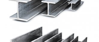
What types of channels are there?
Channels are divided into two groups: hot-rolled and bent. Hot rolled ones are distinguished by clearly defined ribs. For bent metal products they are rounded.
The bent (left) and hot-rolled (right) channel are noticeably visually different
Features of hot rolled channel
According to the shape of the flanges, hot-rolled channels can have parallel edges (designated “P”) or with a slope of internal edges (“U”). The most important characteristic of rolled metal is the section height. It can vary from 50 to 400 mm.
The height, expressed in centimeters, is the channel number. The most in demand is considered to be rolled metal with numbers from 8 to 20. The wall thickness (it varies between 4.2-11.5 mm), width (30-115 mm) and flange thickness (4.8-13) are “tied” to the section height .5 mm). For the manufacture of channels, several grades of steel are used: St3ps, St3sp, St3ps5, St3sp5 and 09G2S.
Read more about the steel grades used in the article “Steel grades that we use in rolled metal.”
Features of bent channels
Bent channels are produced only with parallel flange edges. The height of their section, the width of the shelves and the thickness of the walls vary within the range of 25-410, 26-160 and 2-8 mm, respectively. Such channels are made from the same grades of steel as hot-rolled ones.
Interfloor ceiling on metal beams
The task of floors in a building is to perform load-bearing and enclosing functions, to ensure the spatial rigidity of the structure and its stability, to separate floors, to connect walls to each other, transferring the load to them. In low-rise construction there are several options for arranging interfloor floors. One of them is flooring using metal beams. They can also be used for attic and basement floors.
Advantages of metal floors
Metal structures, unlike wooden beams, are more reliable in terms of fire safety and resistance to biological hazards (mold, mildew). They:
- much stronger than wooden beams, with a smaller thickness they can withstand heavy loads. Their use allows you to save space and provide more usable space;
- can be laid on spans up to 24 meters. The I-beam (channel) section of rolled metal remains static, is resistant to changes in the amplitude of the floors, and is not subject to deflection.
The disadvantages of metal floors include low thermal insulation and sound insulation parameters, as well as the likelihood of corrosion. The latter can be prevented by thorough anti-corrosion treatment of the metal before installation. To eliminate shortcomings in sound insulation, the ends of the I-beams are wrapped in felt, tightly sealed into brick walls with cement mortar, and fixed with anchor bolts.
The large weight of the metal may require the use of a crane when installing the structure. It will be very difficult to change the size of beams, cut or extend them using a welding machine. As a result, it is necessary to very accurately measure the dimensions of the spans before ordering rolled metal from the enterprise.
Lag deflection
Entering some, especially old, houses, even with the naked eye you can notice the deflection of the ceilings of the second floor, or, more rarely, the floor of the first floor, which is a consequence of incorrect calculation of the load-bearing capacity of the logs or exceeding the permissible load on the floors. As the practice of operating multi-storey buildings built in the first half of the 50s of the twentieth century, where wooden interfloor ceilings were used, suggests, by the year 2000, the amount of deflection of the ceilings ranged from 70 to 100 mm, which led to the need for major repairs of the building with strengthening of the load-bearing elements of the floors . And this is provided that an accurate engineering calculation of loads and lag sections is carried out at the design stage. And what can we say about individual development, when the calculation of the load-bearing capacity of the logs was carried out “by eye” on the advice of “competent” specialists.
Very often, the amount of deflection of the joists is influenced by the quality of the material used, excessive moisture in the wood, insufficient thickness of the rolled metal from which the beam is made, and many other different reasons that lead to sagging, for example, the ceiling of the second floor under load. An incorrect calculation of the load-bearing capacity can lead not only to the deflection of the log, but also to the complete destruction of the structure and the collapse of the floor downwards, and when no one expects this.
Flooring on I-beams - preparatory work
At the preparatory stage, perform the following activities:
- Decide on the material that is supposed to be used to make the ceiling of the room, and also study the sequence of actions.
- Develop a working drawing that provides complete information about the design features of the ceiling and the range of materials used.
- Perform calculations confirming the strength characteristics of the building structure and the safety margin necessary for long-term operation.
- Calculate the need for building materials, estimate the amount of expenses, and prepare tools.
- Mount the I-beams, maintaining an interval between the supporting elements of 1–2 m and check the correct installation using a level.
- Assemble panel collapsible formwork along the lower level of the I-beam using laminated plywood or planed boards, provide a flange 15–20 cm high.
- Anchor wooden beams or steel spacers to ensure the formwork structure remains stationary and must support the mass of concrete.
When installing supports, install one wooden beam for each square meter of area, and metal elements 2 times less often. The use of telescopic racks will significantly facilitate the work of fixing the formwork structure. Having completed the preparatory activities, proceed to the main work.
Correct calculation of flooring on metal beams is very important
Reinforcement
The internal metal frame in monolithic concrete provides compressive work, which ensures the original strength of the slab. The volumetric reinforcement structure is formed from a flat welded mesh with cells 15 x 15 cm and longitudinal sections of reinforcement laid on the bottom of each stiffener, which are united by vertical connections with ligation wire or welding. The volumetric dressing step is 20 cm. The ends of the metal rods and mesh are welded to the beams and columns.
For reinforcement, a steel rod with a diameter of 10 - 12 mm (grade A 400C) is taken. The mesh can be created from longitudinal rods with a diameter of 12 mm and transverse rods with a diameter of 0.6 cm. In order for the corrugated sheet to become an external reinforcement, notches (“reefs”) are created on the profile that adhere it to the concrete.
The steel inside the slab is protected by a layer of concrete up to 4 cm thick. To create it, special plastic clamps are used that lift the metal rods above the surface of the bottom of the stiffeners by 20 - 40 mm. The top of the reinforcement is also covered with concrete by 20 - 40 mm.
Concrete slabs on metal I-beams. Is this possible?
Good night, Masters!
Like many people, I thought about building a country house. But the man himself is extremely far from construction. In this regard, I have several questions for you.
I'm sketching out a rough design for the house. According to the plan, I want to create a “second light” above the living room and with a minimum of walls on the first floor - a guest bedroom and a bathroom. And the kitchen, dining room and living room are one. Here is the plan sketched out by my clumsy hand:
Yes, a lot of space is wasted, but the house is being built for a family of 2 people, and in the distant future + one child. Of course, maybe all 10 will work out, but for now that’s it)) In case of a large number of guests, there will be a small guest house on the site. I plan to build the house itself monolithic with permanent formwork. I haven’t decided yet - Velox or Expanded Polystyrene, and then cut off the layer of Expanded Polystyrene from the inside. But there is still 2-3 months left. All the same, the project should be given to professionals to bring it into divine form. I'm thinking of putting hollow slabs on the floors. But the question of what to base them on arose precisely because of the desire for a large space on the ground floor. There are no walls! I racked my brain for a long time whether to give up on space or invent something. Basically, at first the idea came to my mind to build a reinforced concrete frame like this, but I read the reviews and realized that you could go broke on formwork alone. In the end, I came to the idea of building a column in the center on which the beams would rest. Concrete beams of the required length are almost impossible to find - I googled reinforced concrete factories in St. Petersburg (by the way, yes, I will build a house in the Leningrad region), only in Moscow time, but delivery will cost an exorbitant amount.. Wooden ones seem unreliable in this case (4 meters), I settled on metal I-beams.
Laying wooden beams
Builders are aware of the shortcomings of wood and try to reduce them to a minimum. Before installing the ceiling, all wooden parts are treated with antiseptics to prevent rotting and damage by insects. The places where timber beams come into contact with brick, concrete slabs and aerated concrete blocks are insulated with various materials.
And in order to increase fire safety, the wood is treated with solutions that do not allow it to flare up immediately when an open fire appears.
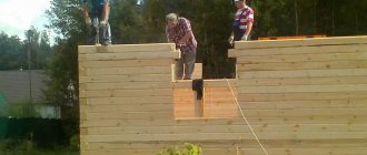
The installation of interfloor structures begins with pre-prepared load-bearing beams. They are laid parallel to the short wall of the home. The laying step depends on the width of the span, but on average it is 1 m. Next, you will need simple materials that provide insulation, and you cannot do without the following tools:
The process of laying a wooden floor from beams and boards
- saws;
- hammer;
- assembly knife;
- roulette;
- construction stapler.
The beams are reinforced with anchors in the niches of the brick wall. But before laying, they make an oblique cut at the ends of the timber and impregnate it with an antiseptic. The area of contact between the wood and the brick is tarred and wrapped in roofing felt. The ends of the supports in the niches must be tightly closed. The gaps can be eliminated with polyurethane foam.
Then floor joists are laid on the supporting beams, and rubber pads are placed under them to reduce the vibration of the structure. The ceiling is lined underneath. Attic and basement ceiling systems require insulation. Interfloor partitions can do without it, but good sound insulation is required.
One of the main structural elements used to construct the floors of attics or second-floor rooms, mainly in low-rise individual construction, is a wooden or metal beam, which simultaneously serves as a floor joist and a base for attaching ceiling coverings. The widespread use of beam floors was facilitated by the low cost of initial building materials and the possibility of constructing floors without the use of lifting mechanisms.
Pros and cons of use in buildings
Metal structures have a number of advantages, due to which the material is widely used:
- increased strength;
- fire resistance;
- resistance to external factors;
- increased reliability;
- long period of operation;
- the ability to strengthen an already constructed building;
- increased load-bearing capacity.
However, such beams also have their disadvantages, which should also be taken into account :
- complexity of construction work;
- the need to use heavy equipment;
- metal may corrode;
- complex calculations are required, which can be very difficult for a beginner.
Requirements for floors
General requirements apply to all interfloor devices:
- Strength is the ability to withstand the weight of all building elements.
- Rigidity that allows you not to bend under the weight of your own weight or heavy things on the floor.
- Effective thermal insulation and sound insulation of floors.
- Fire resistance, which is characterized by resistance to fire for some time.
- Service life corresponding approximately to the time of use of the entire building.
Types of floor beams - advantages and disadvantages
Wooden beams
They are most often chosen as floors in houses made of wood, timber, brick houses and houses built from gas silicate blocks for attic floors, as well as in cases where they want to save on materials, or if the strength of the foundation is not designed for heavy floors between floors , as well as in case of unstable soils on the site.
The main material used for beams of this variation is deciduous and coniferous wood, carefully dried and subjected to special processing, which improves its operational and technical parameters. Such a beam floor includes the beams themselves, insulation, shingles and flooring.
Advantages:
- convenience and ease of installation;
- reasonable cost;
- low weight of the product.
Flaws:
- high level of flammability;
- susceptibility to damage by bark beetles;
- possible rotting of the structure over time;
- The floor structure on wooden beams is used only up to the fourth floor.
In order to simplify the calculation of a wooden beam and the selection of sections and spacing for it, we provide a table that will help determine the preliminary selection of sections for single-span wooden beams. All you have to do is collect the regulatory loads:
During installation, wooden floor beams are laid on transverse supports, which can be an additional beam or an armored belt cast around the perimeter of the masonry wall. Transverse supports serve to evenly distribute the load on the walls, and then on the foundation of the house. Parts of the beams laid on the walls are wrapped in waterproofing material. Typically, roofing felt is used, but the ends are not insulated, which allows the beam to “breathe.”
The most important thing when choosing a material for flooring over wooden beams is to carefully select high-quality wood without cracks, damage, well-dried, impregnated against fire and rot, as well as with a design section of the beams suitable for construction.
In private construction, a common practice is the use of monolithic concrete floors, or other types of the most durable floors on the lower floors of the building, and the simultaneous use of beam floors on higher floors - for example, the attic. This is done in order to lighten the overall loads on the foundation.
Steel beams
Metal floor beams are made of high-strength steel alloy using hot or cold rolling technology. Structurally, they are presented in the form of an I-beam, channel or angle, with I-beams having the greatest demand and popularity. Laying is possible both “flat” and on the edge.
Advantages:
- spans of greater length are permissible than when using wooden beams;
- resistance to biological influences and decay;
- fire resistance.
Wooden beams
In the construction of country houses, larch or pine solid beams are widespread. They are used for the installation of floors 5 m wide. And for large spans, glued ones are used, the strength of which is much higher.
Installation of floors made of wooden beams
Rounded timber is a wonderful building material for floors. It is laid with the north side down, identifying it at the end by the density of the growth rings in the wooden log. In Rus', huts have long been built with the stronger side of the round timber facing out.
A wooden I-beam has high strength. Its profile is the letter “H”, glued together in the factory from three parts. Some craftsmen assemble it in a home workshop or in the country. Interfloor partitions using them provide effective insulation and excellent sound insulation.
Scheme of the construction of wooden floors made of logs
They are very convenient not only for lining the ceiling, laying insulating materials and laying the subfloor, but also for installing all communications. The niches in the I-beam seem to be specially designed for hidden installation of water supply pipes, gas pipelines and electrical wires.
Wooden beams are used in almost any low-rise dwelling: wooden, block. But most of all they are suitable for buildings made of aerated concrete blocks. This material is porous, inferior in strength to all others and cannot withstand the point load of load-bearing beams. Since wood is not heavy, aerated block walls can easily withstand its weight. Installation of the overlapping structure is possible without the use of complex technical means. And it will cost the developer relatively inexpensively.
Main part of the work
Scheme of a monolithic floor.
- reinforcing rod A500C;
- wire;
- mortar 400-500 grade (1 cement, 3 sand, water as needed);
- bayonet shovel;
- shovel;
- polyethylene film;
- water;
- scrap.
Creation of a reinforcing part. In this kind of floors, the use of double lathing is no longer required, but a single one is sufficient. The lathing is done in increments of 0.5 m and is fixed at the level of the middle of the slab (with double lathing, the bottom one is laid at a level of 25 mm from the formwork and the same amount on top, but here you should choose a neutral option). To secure it, you will need to use metal brackets, which can be made manually from the same rod (it can be calculated separately as 0.4 * area / 4). All connections are made tightly with soft wire. After completing the fastening, the reinforcement should be checked for mobility - if possible, it should not be set in motion.
Order the solution. You shouldn't even try to do it yourself, because... It is advisable to fill it in one go. The reason for this is the uniformity of hardening - if this does not happen, then wear may be faster. The solution should be grade 400-500, but not lower, because strength will still be required, despite the beam floors. When making calculations, attention should be paid to one aspect - one automixer contains an average of 8-9 m³ of solution. You should also make sure that the mixer has a sleeve for feeding to the second floor.
Design diagram for flooring using metal beams.
During pouring, it is advisable to have one or two assistants so as not to interrupt the process. They will have to plow the solution to release trapped air. Less air means less to worry about. But at the same time, do not forget about the roofing felt laid in step 5, which should not be damaged. Pouring is done in constant motion so as not to create unnecessary load on the supporting structures. In addition, this will ensure uniformity of work and the opportunity for assistants to do their work independently and as efficiently as possible. If you do everything correctly, the filling is completed in half a day.
Upon completion of the work, cover everything with plastic wrap and leave for 28 days. In this case, you should regularly moisten the stove with water.
A month later, the supporting system is removed, the formwork is dismantled using a crowbar, the polyethylene is removed manually and the main part of the work can be admired.
Final stage
At this stage, care should be taken to hide the I-beams. For this, there are 2 development options - the use of any building mixture (which will make almost all calculations on savings futile), or a suspended stretch ceiling. Most often in country houses in this case they use a suspended ceiling made of plasterboard, because it will be very convenient to install, and the dimensions of the room will not be affected at all. It will also be very convenient with wiring, because... the beams can be drilled without compromising strength.
Installation of corrugated flooring
The beam floor is formed by attaching perforated sheets to the internal/external flanges of the transverse beams. The formwork is then formed when the top fastening of the sheets is selected. The permissible deflection parameters of the corrugated sheet, amounting to 1:250, determine the length of the roll span. Before pouring concrete, temporary supports are placed under the surface of the corrugated sheet to ensure the immobility of the structure.
Metal reinforcement is placed on the deck, and the bottom run-up is concreted using one pass along the gutter. The surfaces of the ceiling and floor are leveled. After the overlap has gained strength, the temporary supports are removed. Mounting a beamless monolith involves some nuances.
Thus, long reinforcing rods (with regular ribbed notches on the surface) are laid along each recess of the profiled sheets. They are knitted with wire to a metal welded mesh, which is laid on top of the profile. Filling is done in one pass. After hardening, the concrete base is covered with a cement screed. Load-bearing corrugated sheeting of grades from H60 to H114 is installed, providing the profile height with the necessary rigidity of the material with a thickness of 0.8 - 1.5 mm.
Profiled sheets are fastened with self-tapping screws 3.2 cm long (head 5.5 mm). Such hardware is screwed in without preliminary drilling, drilling through the channel flange. They are twisted every 20 - 40 cm (into each depression of the profile adjacent to the beam), which ensures the accuracy and spatial rigidity of the installation. The longitudinal overlap of the sheets at the joints is made only above the surface of the beams (value 40 - 60 mm). The joints are screwed through with self-tapping screws every 2 cm.