I-beams are one of the most popular types of metallurgical products. They are used in metal structures of all sizes. The high popularity of I-beams is explained by their extremely successful shape. The H-shaped section provides the best load-bearing capacity for the same area compared to all other cross-section shapes that can be obtained by metallurgical methods. In other words, among all metallurgical products, an I-beam can withstand the highest load with the same weight and length of the beam.
Significant demand for I-beams is provided by automated lines that have extremely high productivity. According to the manufacturing method, hot-rolled and welded I-beams are distinguished. Products obtained by hot rolling are characterized by slightly higher strength. The main advantage of welded I-beams is their very low price. Also, the equipment producing welded I-beams is easy to change over, so this method makes it easier to produce products of non-standard sizes.
Modern lines for the production of I-beams from sheet metal have a high degree of automation. This allows you to maximize productivity and minimize the influence of the human factor. The original sheet is cut into strips, which are welded sequentially.
Cut the sheet
If you need to produce a beam longer than 6 m, then the length of one sheet will not be enough. Therefore, the second sheet or part of it is welded by butt welding. For this operation, a butt welding installation is used, which has a specialized power source. It operates from standard three-phase industrial current, voltage 380 V and frequency 50 Hz. The welding current source acts as a converter. The output current from it has a strength in the range of 150 - 1300 A and a voltage of 16 - 46 V.
Butt welding can join sheets up to 30 mm thick in one operation. This installation can significantly reduce the need for maintenance personnel and increase the overall productivity of the line.
After welding, the sheet is fed to a machine that performs flame cutting. Portal type machines show high efficiency. The sheet is placed on the machine's work table on rails and cut into longitudinal strips. From one sheet you can make up to 9 stripes in one pass. The machine can perform transverse and even curved cuts. These functions are required to obtain blanks for cross-section beams. For complex operations, two CNC torches are used, which can cut at any angle.
Adjusting the speed of the cutting machine allows you to adjust it as needed depending on the thickness of the sheet. Acetylene and oxygen are used for cutting, propane can also be used. The operation of the machine is controlled by the Australian FASTCAM 1 program, which is designed specifically for devices of this type. Its advantages are:
- Deep integration of automatic control;
- Ability to work in manual mode;
- Optimization of cutting of sheet material;
- Ability to control multiple cutting heads;
- Calculation of the minimum working path.
The maximum width of the sheet available for cutting is 4 m, and the length is 14 m. The minimum cutting width is 80 mm. The cutting machine has 9 longitudinal burners and two pepper burners. When they work together, it is possible to cut sheets with a thickness of 6 – 50 mm. Steel up to 100mm thick can be cut when using no more than 5 torches. The energy consumption of the installation is only 1.5 kW.
How to weld I-beams
The design of the assembly equipment used to manufacture welded beams having an I-section is determined by the welding method used to form the waist seams. The choice of such equipment also depends on what devices are planned to be used in the production process. At modern enterprises, automatic submerged arc welding is most often used to form long belt seams of I-beams. This method allows us to obtain welds of high quality and reliability along their entire length.
Beam welding as a stage of its manufacture
The use of automated equipment for welding under a layer of liquid flux to produce I-beams allows not only to reduce the cost of the finished product, but also to ensure its high quality and reliability. The operating principle of such equipment provides that the unmelted flux protecting the welding zone is under pressure. Thanks to this, the splashing of liquid metal from the welding zone is minimized, which allows this operation to be performed efficiently even at high current values (up to 4 thousand Amperes). In addition, the flux protects the molten metal from rapid cooling, which facilitates more efficient removal of gas from it.
Meanwhile, the welded beam can be produced using manual arc and semi-automatic welding. In such cases, special conductors with clamping elements, or ordinary tacks and clamps are used to assemble them. However, it should be borne in mind that in this case you will have to deal with large losses of molten metal, which will occur due to its splashing and waste. Such losses can reach up to 30%.
Beam assembly
After cutting the sheet material, the blanks are fed to the assembly mill. They are moved by a crane. The beam is assembled using clamps that fix the parts horizontally and vertically. First, the T-beam is assembled - a horizontal strip is placed on the conveyor, the position of which is determined by the side guides. A vertical stand is placed on the strip, which is centered and clamped by side guide stops.
The assembled structure is fed to the vertical stop, which automatically aligns the end, and moves into the welding portal. There it is additionally fixed with a hydraulic clamp from above to eliminate the gap between the parts. The conveyor feeds the beam forward, and it is welded on both sides by automatic welding. Spot welding is used, which is formed through a given step. The welding installation is located in the same plane as the fixing hydraulic cylinder.
The resulting T-beam is bent 180° and transferred back to the assembly area, where the workpiece for the second flange is placed on it. Further operations are similar - positioning, fixing with clamps and passing through the welding portal. This creates a pre-assembled beam. The completed welded connection has low strength and is intended for the convenience of further manipulation of the beam, and not for full load absorption.
The machine for assembling beams allows you to assemble products of different types of H-shaped profiles:
- Symmetrical;
- Asymmetrical;
- With variable cross section.
The welding assembly speed is 500 – 6000 mm/min with a maximum power consumption of 107 kW. The machine allows you to create beams with the following parameters:
- Stand thickness – 6-32 mm;
- Shelf thickness – 6-40 mm;
- Stand height – 200-1500 mm;
- Shelf width – 200-600 mm;
- Beam length – 4000-15000 mm.
It is clear from the dimensions that the machine makes it possible to assemble an I-beam, the dimensions of which significantly exceed the maximum dimensions of products described in GOST 26020–83 for hot-rolled I-beams with parallel flanges. According to this document, the largest dimensions are beam 100B4 with a height of 1014 mm and a flange width of 320 mm. The production of non-standard hot-rolled beams is carried out only in large quantities due to the high cost of tools. Also, the maximum beam size is limited by the dimensions of the rolling mill.
Advantages of welded I-beams
Nowadays, it is very difficult to find a construction project that was erected without the use of welded I-beams. Beams with this cross-section are widely used because they can significantly reduce the costs of constructing structures for various purposes, while ensuring high reliability of the structures being built.
A welded beam, the cross-section of which has the shape of an I-beam, is capable of withstanding significant static and dynamic loads without losing its performance characteristics. An important factor is that the use of such welded beams makes it possible to reduce the weight of building structures, which ultimately reduces the load on the foundation of the building and on its supporting structures.
The use of I-beams in the manufacture of a building frame
A welded I-beam is especially indispensable in those elements of building structures where strength and the ability to successfully withstand mechanical loads of various directions are especially important. Such elements, in particular, include frames for various structures, columns, interfloor ceilings, overpasses, work platforms, etc.
Welded beams are in great demand in various branches of mechanical engineering and in the construction of prefabricated structures, since the technology for its production is very economical.
Despite the fact that it is quite simple to organize the production of welded I-beams, it is more economically profitable to produce them using automated equipment. Automated lines on which the production of such welded beams is put on stream allow not only to significantly reduce the cost of production, but also to strictly adhere to the technology of its production.
Floors on metal I-beams
Feeding beams to the first welding installations
The beam that comes out of the spot welding machine is in a vertical position. It moves along the conveyor in this position and reaches the tilter, which rotates the beam by 90°. He places the beam horizontally on the conveyor.
The beam is transferred to a pair of hydraulic trolleys.
They are located sequentially, between the welding installations. The trolleys work in pairs and have a total load capacity of 20 tons. They lift the beam to a height of up to 140 mm. The trolley's power consumption is 1.5 kW.
When the beam hits the carts, the conveyor stops. They lift the beam over the conveyor. Next, the carts move along rails located perpendicular to the conveyor. The trolleys deliver the beam to a hydraulic tilter, which turns it 45°.
The lifting capacity of the tilter is also 20 tons. It can work with beams with a height of 200 – 2000 mm and a width of 200 – 1000 mm.
After this, the first welding seam is made. The beam is in the boat position. The welding unit moves along rails and performs the welding seam. It can weld metal with a thickness of 6 – 40 mm. The permissible beam height is 200 – 2000 mm, and the width is 200 – 800 mm. The length of the seam can reach up to 15 m. The welding speed is in the range of 350 – 1500 mm/min. The welding power is 65 kW, and the drive power is 5.1 kW.
Next, the tilter returns the beam to a horizontal position. The trolleys receive the beam and transfer it to the tilting machine of the second welding installation, which is located in parallel. This installation has exactly the same design. Upon completion of the second welding seam, the beam lies horizontally and is returned to the conveyor using carts.
Cost of equipment
The price includes services: installation supervision, setup, training, warranty and maintenance for 12 months.
- Country of origin: China.
- Payment procedure:
- 50% - advance payment within 5 banking days from the date of signing the Agreement.
- 45% - within 5 banking days from the date of written notification of the completion of production of the equipment by the manufacturer and the readiness of its shipment to the destination station with the provision of an electronic copy of shipping documents (a duplicate of the invoice) and a certificate of origin form "A", certified by signature and seal Supplier.
- 5% - after completion of commissioning and signing of the certificate of commissioning and acceptance of equipment for quality.
- Delivery time : 60 calendar days from receipt of advance payment.
Turning and welding the remaining seams
As a result of the previous operations, a beam is obtained, on one side of which the seams are made. However, it is on the conveyor in a horizontal position, with the finished seams facing up. Therefore, an additional tilter is used, which turns the beam over, and it is placed on the conveyor with the seams made down. This tilter also has a hydraulic drive and a lifting capacity of up to 20 tons. It can work with products with dimensions of 1000 x 2000 mm. The turning speed is 1000 mm/min. The tilter consumes 18 kW of electricity.
The third and fourth welds are made in a similar way. The beam is also tilted by 45° and the seams are successively welded using a pair of welding machines.
Equipment for the production of wooden construction beams
An I-beam consists of two wooden shelves connected by a stud made of plywood or OSB. Sometimes LVL timber is used in beam flanges. I-beams, compared to traditional wooden floors, weigh less, cover large spans and do not change geometry over time. Conventional wooden plank floors are subject to shrinkage, torsion and cracking as the wood shrinks. As a result, creaks and uneven floors appear. For the production of SK beams, defect-free, chamber-dried lumber with a moisture content of no more than 18% is used, connected with a special two-component glue with a stiffener made of OSB-3 (oriented strand board) or high-quality plywood. The result of the application (I-beam) is easy to install, affordable and guaranteed comfortable floors.
The group offers automatic and semi-automatic lines for the production of turnkey wooden construction beams. Equipment for formwork beams has different capacities.
I. Workshop for the production of spliced boards for shelves of I-beam wooden BDK
1. Roller conveyor RT-40
| Specifications | |
| Width (mm) | 400 |
| Length (mm) | 7000 |
| Height (mm) | 900 |
| Weight (kg) | 210 |
2. Multi saw MJ143E
| Specifications | |
| Maximum cutting height (mm) | 10 — 120 |
| Maximum cutting width (mm) | ≤ 750 |
| Maximum distance between edge saws (mm) | 300 |
| Minimum length (mm) | 585 |
| Saw diameter (mm) | 380 |
| Saw mounting diameter (mm) | 70 |
| Saw rotation speed (rpm) | 4000 |
| Saw unit power (kW) | 37 |
| Feed motor power (kW) | 2,2 |
| Feeding speed (m/min) | 7,5 — 30 |
| Installed power (kW) | 39,6 |
| Overall dimensions, mm) | 2300 x 1500 x 1450 |
| Machine weight (kg) | 2300 |
3. Cross conveyor TsT-6
| Specifications | |
| Conveyor length (m) | 3,5 |
| Conveyor height (mm) | 1000 |
| Conveyor width (m) | 6 |
| Distance between traction chains (m) | 1,5 |
| Number of traction chains (pcs) | 4 |
| Feeding speed (m/min) | 5 |
| Invertible motor drive power (kW) | 3 |
4. Four-sided machine V-HOLD VH-M418
| Specifications | |
| Number of spindles (pcs) | 4 |
| Workpiece length (mm) | from 200 |
| Processing width(mm) | 18 — 180 |
| Processing height (mm) | 8 — 130 |
| Feeding speed (m/min) | 6 — 36 |
| Spindle speed (rpm) | 6000 |
| Feed motor power (kW) | 3,0 |
| Bottom spindle power (kW) | 4,0 |
| Right spindle power (kW) | 4,0 |
| Left spindle power (kW) | 4,0 |
| Upper spindle power (kW) | 5,5 |
| Traverse lift motor power (kW) | 0,55 |
| Total power (kW) | 21,0 |
| Spindles diameter (mm) | 40 |
| Tool diameter on 1st spindle (mm) | 125 |
| Tool diameter on vertical spindles (mm) | 125 — 180 |
| Tool diameter on horizontal spindles (mm) | 125 — 180 |
| Feed roller diameter (mm) | 140 |
| Exhaust pipe diameter (mm) | 140 |
| Overall dimensions, mm) | 3500 x 1500 x 1600 |
| Machine weight (kg) | 2700 |
5. MATRIX 1-6000 defect optimization line
| Specifications | |
| Maximum workpiece cross-section (mm) | 250 x 95 |
| Maximum workpiece length (mm) | 6000 |
| Pusher feed speed (m/min) | 0 — 80 |
| Processing accuracy (mm) | 0,5 |
| Saw rotation speed (rpm) | 3000 |
6. TR 450 (SAW UNIT)
| Specifications | |
| Maximum processing thickness (mm) | 95 |
| Saw blade diameter (mm) | 450 |
| Table height (mm) | 850 |
| Working pressure (MPa) | 0,8 |
| Diameter of aspiration pipe (mm) | 2 x 100 |
| Spindle speed (rpm) | 3000 |
| Motor power (kW) | 4,1 |
| Machine weight (kg) | 310 |
7. Belt conveyor from optimization line to splicing line CB-6
| Specifications | |
| Motor power (kW) | 1,5 |
| Overall dimensions, mm) | 6000 x 700 x 450 |
8. Automatic line for length splicing
“AFJ120”
| Specifications | |
| Maximum lash length (mm) | 12000 |
| Maximum lash width (mm) | 150 |
| Maximum lash height (mm) | 80 |
| Input belt conveyor | MF7A |
| Table length (mm) | 600 |
| Table width (mm) | 1150 |
| Motor power (kW) | 0,375 |
| Automatic tenon cutter for splicing | MX3515/II |
| Carriage work table size (mm) | 850 x 600 |
| Maximum workpiece size (mm) | 850 x 80 x 150 |
| Minimum workpiece size (mm) | 200 x 30 x 20 |
| Tenon cutter size (mm) | 160 x 70 |
| Saw blade size (mm) | 255 |
| Spindle speed (rpm) | 5000 |
| Main saw spindle speed (rpm) | 2840 |
| Working air pressure (MPa) | 0,8 |
| Total power (kW) | 16,12 |
| Conveyor belt between tenoners | MF7B |
| Table length (mm) | 700 |
| Table width (mm) | 1150 |
| Motor power (kW) | 0,375 |
| Automatic tenon cutter for glue jointing | MX3515T/II |
| Carriage work table size (mm) | 850 x 600 |
| Maximum workpiece size (mm) | 850 x 80 x 150 |
| Minimum workpiece size (mm) | 200 x 30 x 20 |
| Tenon cutter size (mm) | 160 x 70 |
| Saw blade size (mm) | 255 |
| Spindle speed (rpm) | 5000 |
| Main saw spindle speed (rpm) | 2840 |
| Working air pressure (MPa) | 0,8 |
| Total power (kW) | 18,74 |
| Roller conveyor | MF74 |
| Motor power (kW) | 0,375 |
| Chain conveyor including ejector | MF76 |
| Motor power (kW) | 0,375 |
| Automatic Two Section Splicing Press | MHZ15120 |
| Max working size(mm) | 12000 x 150 x 80 |
| Minimum working size (mm) | 1000 x 30 x 20 |
| Maximum pressing force (kg) | 7800 |
| Maximum saw diameter (mm) | 355 |
| Miter saw rotation speed (rpm) | 3500 |
| Total power (kW) | 8,45 |
| Total line power (kW) | 45 |
| Overall dimensions, mm) | 21000 x 5450 x 1800 |
| Line weight (kg) | 7800 |
9. Automatic feeder F-80 with a transverse conveyor for a four-sided machine
| Specifications | |
| Working length (mm) | 1800 — 6100 |
| Working width (mm) | 50 — 230 |
| Working thickness (mm) | 12 — 100 |
| Feeding speed (m/min) | 20 — 100 |
| Total power (kW) | 5,15 |
| Roller diameter (mm) | 160 x 50 |
| Overall dimensions, mm) | 5900 x 3200 |
10. 6-spindle high-speed four-sided machine V-HOLD VH-M616GH
| Specifications | |
| Number of spindles (pcs) | 6 |
| Workpiece length (mm) | from 200 |
| Processing width(mm) | 18 — 160 |
| Processing height (mm) | 8 — 110 |
| Feeding speed (m/min) | 10 — 60 |
| Spindle speed (rpm) | 7500 |
| Feed motor power (kW) | 5,5 |
| Bottom spindle power (kW) | 5,5 |
| Right spindle power (kW) | 5,5 |
| Left spindle power (kW) | 7,5 |
| Upper spindle power (kW) | 7,5 |
| Second upper spindle power (kW) | 5,5 |
| Second lower spindle power (kW) | 5,5 |
| Traverse lift motor power (kW) | 0,75 |
| Total power (kW) | 43,25 |
| Spindles diameter (mm) | 40 |
| Tool diameter on 1st spindle (mm) | 125 |
| Tool diameter on vertical spindles (mm) | 125 — 160 |
| Tool diameter on horizontal spindles (mm) | 125 — 160 |
| Feed roller diameter (mm) | 140 |
| Exhaust pipe diameter (mm) | 140 |
| Machine weight (kg) | 5200 |
11. F-28 receiver
| Specifications | |
| Working length (mm) | 1800 — 6100 |
| Working width (mm) | 50 — 230 |
| Working thickness (mm) | 12 — 100 |
| Acceptance speed (m/min) | 20 — 100 |
| Total power (kW) | 0,37 |
12. Cross conveyor TsT-6
| Specifications | |
| Conveyor length (m) | 3,5 |
| Conveyor height (mm) | 1000 |
| Conveyor width (m) | 6 |
| Distance between traction chains (m) | 1,5 |
| Number of traction chains (pcs) | 4 |
| Feeding speed (m/min) | 5 |
| Drive power of invertible electric drive (kW) | 3 |
II. Workshop for the production of racks (walls) of formwork beams (I-beams)
13. Vacuum loading + feeding conveyor
| Specifications | |
| Stacker dimensions (mm) | 4000 x 3000 x 2800 |
| Maximum loader weight (kg) | 2000 |
| Pump power (kW) | 4 |
| Feed Conveyor Dimensions (mm) | 3000 x 2500 x1000 |
| Conveyor weight (kg) | 600 — 800 |
| Feeding power (kW) | 1 |
14. Multi-saw machine for plywood FCU-13
| Specifications | |
| Maximum cutting width (mm) | 1300 |
| Saw dimensions (mm) | 205 |
| Installed power (kW) | 24 |
| Kerf thickness (mm) | 6 — 15 |
| Overall dimensions, mm) | 3200 x 1200 x 1200 |
| Machine weight (kg) | 1900 |
15. Roller conveyor RT-40
| Specifications | |
| Width (mm) | 400 |
| Length (mm) | 7000 |
| Height (mm) | 900 |
| Weight (kg) | 210 |
16. Longitudinal four-sided milling machine V-HOLD VH-M418
| Specifications | |
| Number of spindles (pcs) | 4 |
| Workpiece length (mm) | ≥ 200 |
| Workpiece width (mm) | 18 — 180 |
| Workpiece height (mm) | 8 — 130 |
| Feeding speed (m/min) | 6 — 36 |
| Spindle speed (rpm) | 6000 |
| Feed motor power (kW) | 3,0 |
| Bottom spindle power (kW) | 4,0 |
| Right spindle power (kW) | 4,0 |
| Left spindle power (kW) | 4,0 |
| Upper spindle power (kW) | 5,5 |
| Traverse lift motor power (kW) | 0,55 |
| Total power (kW) | 21,0 |
| Spindles diameter (mm) | 40 |
| Tool diameter on 1st spindle (mm) | 125 |
| Tool diameter on vertical spindles (mm) | 125 — 180 |
| Tool diameter on horizontal spindles (mm) | 125 — 180 |
| Feed roller diameter (mm) | 140 |
| Exhaust pipe diameter (mm) | 140 |
| Overall dimensions, mm) | 3500 x 1500 x 1600 |
| Machine weight (kg) | 2700 |
17. Cross-cutting machine TsT10-4
| Specifications | |
| Maximum processing thickness (mm) | 100 |
| Maximum processing width (mm) | 500 |
| Saw carriage stroke (mm) | 500 |
| Diameter of installed saw (mm) | 400 x 50 |
| Saw rotation speed (rpm) | 2850 |
| Workpiece feed drive | Manually |
| Crosshead rotation angle (°) | 90 |
| Motor power (kW) | 3 |
| Overall dimensions, mm) | 4520 x 950 x 1350 |
| Machine weight (kg) | 360 |
18. Double-sided tenoning machine MX3826D
| Specifications | |
| Processing width(mm) | 300 — 2600 |
| Workpiece thickness (mm) | 10 — 70 |
| Feeding speed (m/min) | 5 — 20 |
| Distance between positioning blocks (mm) | 240 |
| Miter saw speed (rpm) | 3000 |
| Rotation speed of 1st milling spindle (rpm) | 7000 |
| Rotation speed of 2nd milling spindle (rpm) | 8000 |
| Saw mounting diameter (mm) | 25,4 |
| Milling cutter diameter (mm) | 30 |
| Saw diameter (mm) | 200 — 250 |
| Diameter of cutters on 1st spindle (mm) | 108 — 180 |
| Diameter of cutters on the 2nd spindle (mm) | 120 — 150 |
| Total power (kW) | 26 |
| Feed motor power (kW) | 2,2 |
| Motor power on 1st spindle (kW) | 3.0 x 2 |
| Motor power on 2nd spindles (kW) | 2.2 x 2 |
| Saw motor power (kW) | 3.0 x 4 |
| Miter Saw Motor Power (kW) | 3.0 x 2 |
| Motor power for moving left and right calipers (kW) | 0,75 |
| Traverse lifting power (kW) | 0.37 x 2 |
| Number and diameter of aspiration pipes (mm) | 8 x 100 |
| Overall dimensions, mm) | 4800 x 3300 x 1600 |
| Machine weight (kg) | 4350 |
III. Wooden construction beam assembly and painting workshop
19. Driven roller conveyor RTR-40
| Specifications | |
| Total power (kW) | 3,5 |
| Width (mm) | 400 |
| Length (mm) | 7000 |
| Height (mm) | 900 |
| Weight (kg) | 210 |
20. Glue-applying machine KL-250/B-1
| Specifications | |
| Workpiece profile | According to the agreed profile drawing |
| Workpiece length (mm) | 1500 — 6000 |
| Adhesive used | 2-component; polyurethane |
| The ratio of the components of the glue | 100:100 — 100:30 |
| Glue application density (g/lm) | 10 |
| Possibility of adjusting the glue supply (g/m.) | 6 — 20 |
| Glue supply control | Operator panel |
| Workpiece feed speed (m/min) | 15 — 30 |
| Compressed air consumption (l/min) | no more than 50 |
| Pressure in the pneumatic system (bar) | 6 |
| Power consumption (kW) | 1,5 |
21. Hydraulic press for beam B-1
| Specifications | |
| Maximum beam length (mm) | 6050 |
| Number of hydraulic clamps (pcs) | 26 |
22. Cross conveyor TsT-6
| Specifications | |
| Conveyor length (m) | 3,5 |
| Conveyor height (mm) | 1000 |
| Conveyor width (m) | 6 |
| Distance between traction chains (m) | 1,5 |
| Number of traction chains (pcs) | 4 |
| Feeding speed (m/min) | 5 |
| Invertible motor drive power (kW) | 3 |
23. Milling and grooving machine F160
| Specifications | |
| Max Length(mm) | 6050 |
| Spindle stroke (mm) | 350 |
| Number of spindles (pcs) | 4 |
| Rotation speed (rpm) | 6700 |
24. Transverse conveyor TsT-6
| Specifications | |
| Conveyor length (m) | 3,5 |
| Conveyor height (mm) | 1000 |
| Conveyor width (m) | 6 |
| Distance between traction chains (m) | 1,5 |
| Number of traction chains (pcs) | 4 |
| Feeding speed (m/min) | 5 |
| Invertible motor drive power (kW) | 3 |
25. Paint booths of pass-through type LSPM400
| Specifications | |
| Workpiece width (mm) | 10 — 400 |
| Workpiece thickness (mm) | 10 — 100 |
| Minimum workpiece length (mm) | 700 |
| Feeding speed (m/min) | 0 — 50 |
| Number of spray guns (pcs) | 6 |
| Installed power (kW) | 2,25 |
| Compressed air pressure (MPa) | 0,5 — 0,8 |
| Overall dimensions, mm) | 3500 x 1700 x 2000 |
| Machine weight (kg) | 1600 |
26. Marker for wooden I-beam
Rotating and editing a beam
After welding all the seams, the beam is placed on the conveyor in a horizontal position. The tilter rotates the beam 90°, positioning it vertically. After this, the beam will go to the installation, which corrects the mushroom shape of the shelves. The need for this operation arises because when welding with a continuous seam, deformations of the flanges occur.
The installation performs rolling of the lower shelf with rollers. After this, the conveyor returns the beam to the tilter, which rotates the beam 180°. The beam turns out to be straightened with its flange facing up. After this, it goes through the installation again to straighten the shelves.
Depending on the size of the I-beam, one of the straightening installations is used. The device with the highest power (32 kW) is capable of straightening beams up to 800 mm high and up to 1500 mm high. The shelf thickness can reach up to 80 mm. Straightening is performed at a speed of 5.2 m/min. The force on the rollers is 2 mN.
Technical specifications
| Item no. | Parameter | Designation | Meaning |
| 1 | Shelf width | b1, b2 | 200~800mm |
| 2 | Height of welded beam | h | 200~1800mm |
| 3 | Shelf thickness | c1, c2 | 6~40mm |
| 4 | Wall thickness | tw | 6~32mm |
| 5 | Beam length | l | 4000~15000mm |
Attention! If the table does not fit in width, then it can be moved left or right across the screen.
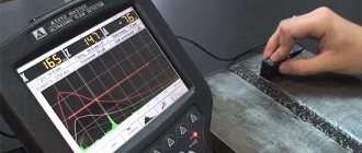
Shot blasting
A welded and straightened beam most often has contamination, primarily rust and scale. A shot blasting machine is used to clean the profile. It also improves the surface quality of the I-beam, making it easier to coat.
The shot blasting machine accelerates steel or cast iron shot to a speed of 60 - 70 m/s and feeds it into the processing chamber. The chamber has eight shot blasters, which are arranged in a circle. There are two shot blasters on the outer sides of the shelves and the counter. The internal edges of the shelves are processed with one shot blaster.
The power of shot blasting machines is in the range of 11-15 kW. The product passes through the chamber at a speed of 0.6 - 3 m/min, shot consumption is 90-120 t/h. These machines can process profiles measuring 1200x2000 mm.