Welding flame
is obtained by combustion of a mixture of flammable gases (or vapors of flammable liquids) and oxygen in the mouthpiece of a welding torch. Depending on what gas is used for gas welding and on the ratio in which it burns with oxygen, three types of welding flame are distinguished: normal (or reducing), oxidizing, carburizing.
Welding flame formation
A combustion reaction usually occurs when solid, liquid or gaseous substances combine with oxygen.
However, some metals can burn not only in oxygen. For gas-flame processing processes, the combustion of various flammable gases in oxygen or air is of greatest importance. The combustion of any gas mixture begins with its ignition at a certain temperature, depending on the conditions of the combustion process. A stable combustion process is possible only if the amount of heat released during combustion of the combustible mixture is sufficient to heat new portions of gas and compensate for heat losses to the environment. A necessary condition for gas combustion in oxygen or air is the content of flammable gas in the mixture within certain limits, called ignition limits.
Depending on the ignition speed of the combustible mixture (the speed of flame spread), three types of combustion are distinguished: quiet - with a flame spread speed not exceeding 10 ... 15 m/s; explosive - with a flame propagation speed reaching several hundred meters per second; detonation - with a flame propagation speed of more than 1,000 m/s.
The ignition rate depends on the composition of the gas mixture and its pressure; the nature and volume of space in which combustion occurs; thermomechanical conditions at its boundary (for example, when a mixture burns in tubes, the main parameter that determines these conditions is the diameter of the tube); purity of combustible gas and oxygen (with an increase in the content of impurities in them, the ignition rate decreases).
The flammable gases used in gas-flame processing are predominantly mixtures of hydrocarbons with other gases; only hydrogen is used in its pure form. All flammable gases containing hydrocarbons form a flame with a luminous core, similar in structure to an oxygen-acetylene flame. The more carbon there is in the combustible gas, the sharper the luminous core of the flame is outlined. Unlike hydrocarbon gases, a hydrogen-oxygen flame does not form a luminous core, which makes it difficult to control the flame by appearance.
Gas welding. Composition and structure of the welding flame. Interaction of flame with metal.
Oxy-acetylene flame welding is effective in repair work. However, this is a low-productivity process that requires a highly qualified welder.
Gas welding uses a high-temperature flame produced by the combustion of acetylene gas mixed with oxygen to heat and melt metal. In some cases, instead of acetylene, its substitutes can be used: propane-butane, methane, gasoline or kerosene vapor, MAF.
Combustible gas and oxygen from cylinders (or a special gas generator) enter the welding torch, where they are mixed in a certain ratio and ignited at the exit from the nozzle. The flame melts the edges of the work being welded and the filler wire, and also serves as protection for the molten metal from the atmosphere. Adjustment of oxygen and fuel gas flow is carried out by appropriate valves.
The acetylene-oxygen flame consists of three zones: core –1, reduction (middle) zone – 2 and torch –3. In the first zone, pyrogenic decomposition of acetylene occurs in the presence of oxygen into carbon and hydrogen; in the second, the combustion of carbon in oxygen coming from the burner; in the third - further oxidation of the products of combustion and decomposition reactions (CO and H2) with oxygen sucked in from the environment. The maximum temperature develops in the middle zone, in which the welded metal is located.
Structure and types of gas flame (a) and their temperature characteristics (b); 1 – core, 2 – reduction zone, 3 – torch.
If the volume of oxygen is less than the volume of acetylene, then when acetylene is burned, free carbon atoms will remain, which will increase the carbon content in the surface layers of the metal. This is sometimes used to strengthen the surface layers of the product.
If the flame contains excess oxygen, it strongly oxidizes the metal. This flame is called oxidizing and is usually used only for heating metal.
Multi-station welding transformers
In large welding shops, welding stations can be located in separate groups at a great distance from each other. In this case, groups of posts can be powered from a multi-station welding transformer. Welding stations are connected to the transformer in parallel to each other. The main condition for stable operation with multi-post feeding is the independence of the operating mode of each post from the operation of other posts. To achieve this, it is necessary that the power supply voltage does not change with changes in load, i.e. The external current-voltage characteristic of the power supply must be rigid.
For multi-station welding, you can use a transformer with normal dissipation, which has a rigid current-voltage characteristic.
Connection diagram of welding stations to a transformer with normal dissipation
For multi-station welding, three-phase transformers are used with parallel power supply to several welding stations.
The phase voltage should be 65-70 V. Regulation of the welding current and the formation of the falling characteristic at each station is carried out using a choke or ballast rheostat.
The number of posts that can be connected to the power source can be calculated using the formula.
– number of posts
– rated current of the multi-station welding transformer
– welding current of the station
– load factor.
Multi-station welding transformers have disadvantages: large voltage and energy losses in the low-voltage welding circuit; in the event of a failure of a multi-station transformer, a large number of welding stations will be idle. To avoid this, it is necessary to have redundant transformers, which increases equipment costs. These disadvantages limit the use of multi-post transformers; for the same reasons, the number of posts does not exceed 9 - 12.
studfiles.net
Welding flame structure
The combustion process of flammable gas begins with the ignition of the gas at a certain temperature, depending on the conditions under which the combustion process occurs. After the start of combustion, further heating of the gas from an external source is not required if the heat released during combustion is sufficient to maintain the combustion of new portions of the combustible mixture and compensate for heat losses to the environment.
Depending on the progress of the acetylene combustion reaction, the welding oxygen-acetylene flame has a certain shape (Fig. 1). In the inner part of the flame core 1, the gas mixture coming from the mouthpiece is gradually heated to the ignition temperature. In the flame core, thermal decomposition of acetylene occurs, which is accelerated by the presence of oxygen in the core supplied to the burner. Acetylene in the flame core
decomposes by reaction
C2H2 + O2 → 2C + H2 + O2 (2.1)
The resulting carbon is tiny solid particles that surround the flame core in a thin, hot layer, causing it to glow. The core shell is the brightest part of the welding flame with a temperature of about 1,500 °C. By the appearance of the core, you can visually determine the composition of the gas mixture and the serviceability of the welding torch.
In the middle zone 2 of the flame, incomplete oxidation of carbon by oxygen in the mixture occurs according to the reaction
2C + H2 + O2 → 2CO + H2 (2.2)
The released heat helps to heat the mixture and accelerate the oxidative processes occurring in it. Middle zone 2 is characterized by maximum temperature (Fig. 2).
Rice. 1. Structure of a welding flame : a - normal flame: 1 - core; 2 - middle zone; 3 - torch; b - oxidizing flame (with excess oxygen); c - carburizing flame (with excess acetylene)
In the torch 3 of the flame, carbon monoxide and hydrogen burn out when they interact with oxygen coming from the air:
2СО + Н2 + 1.5О2 K 2СО2 + Н2О (2.3)
with the release of a large amount of heat. However, due to the large volume of flame zone 3, the temperature in it is lower than in middle zone 2.
Rice. 2. Temperature distribution t along the axis of the oxygen-acetylene flame : 1 - core; 2 - middle zone; 3 - torch
Rice. 3. Dependence of the maximum flame temperature t on the oxygen content in the gas mixture
To form a normal flame (see Fig. 1, a) and complete combustion of acetylene, it is necessary to supply the same volume of oxygen to the burner for each volume of it (ratio β = Vк/Vа = 1). A normal flame is obtained at β = 1.1 ... 1.3.
When this ratio increases (β > 1.3), an oxidizing flame is obtained, since it contains excess oxygen, which oxidizes the metal. In this case, the flame core shortens, becomes pointed, with less sharp outlines (see Fig. 1, b), turns pale and acquires a bluish color.
When the amount of incoming oxygen decreases (excess acetylene), a carburizing flame is obtained (see Fig. 1, c). At the same time, the volume of the middle zone increases, the core becomes blurry, and a greenish “acetylene feather” appears behind it. With a significant excess of acetylene, carbon particles appear in the outer zone, the flame becomes smoky, lengthens and acquires a reddish color.
It has been established that the highest flame temperature and the highest welding performance are observed with a certain excess of oxygen in the mixture compared to a normal flame (Fig. 3). The maximum temperature for sufficiently pure oxygen and acetylene can be taken to be 3,100 ... 3,200 °C.
The structure of the flame of substitute gases, which include hydrocarbons, does not differ significantly from the structure of an acetylene-oxygen flame, but has a less pronounced luminous core, which makes it difficult to regulate the composition of the flame by appearance.
Normal (recovery) type of welding flame
A welding flame is considered normal when acetylene is burned in oxygen in the ratio O2/C2H2=1. But in practice, oxygen is supplied with impurities, not pure. Therefore, a normal flame turns out when the ratio of oxygen and acetylene is in the range of 1-1.3. This type of flame has a positive effect on the deoxidation of molten metal and the achievement of high quality welding.
Welding of most metals and alloys is performed with a normal flame, especially often when welding low-carbon steels. When gas welding aluminum, a normal welding flame with a slight excess of acetylene is used.
Thermal characteristics of the welding flame
Flame temperature is one of the most important parameters that determine its thermal properties. The higher the temperature, the more efficient the heating and melting of the metal.
Since the middle zone, containing carbon monoxide and hydrogen, also has reducing properties, welding is naturally carried out in this zone, positioning the torch so that the flame core is at a distance of 2 ... 3 mm from the metal surface.
The ratio of the mixture of combustible gas with oxygen has a significant influence on the flame temperature. With increasing β, the temperature maximum increases and shifts towards the burner mouthpiece, which is explained by an increase in the rate of combustion of the mixture with an excess oxygen content in it.
The temperature of the oxy-acetylene flame of a welding torch with a specific acetylene consumption of 250 ... 400 dm3/h with a gas mixture ratio β = 1.1 ... 1.2, depending on the distance to the inner core of the flame, changes as follows:
| Distance, mm | 3 | 4 | 11 | 25 |
| Temperature, °C | 3 050 … 3 150 | 2 850 … 3 050 | 2 650 … 2 850 | 2 450 … 2 650 |
With a change in the mixture ratio, the flame temperature changes significantly, reaching maximum values at increased oxygen content.
Heating of metal by flame is caused by forced convective and radiant heat exchange between the flow of the flammable mixture of the flame and the area of the metal surface in contact with it. Radiant heat transfer is small - 5 ... 10% of the total heat transfer between flame and metal, therefore the welding flame can be considered as a convective heat transfer source.
The intensity of forced convective heat transfer depends on the temperature difference between the flame and the heated metal surface, as well as on the speed of the flame flow relative to this surface.
In general, the specific heat flux of the flame q2, which is the amount of heat introduced by the flame per unit time through a unit area of the heated metal surface, can be expressed by Newton’s rule:
q2 = a(Tn - T), (2.4)
where a is the heat exchange coefficient between the flame and the metal, equal to the sum of the forced convective and radiant heat exchange coefficients, W/(m2 K); Tp is the temperature of the flame gas flow, K; T is the temperature of the metal surface towards which the flame flow is directed, K.
Coefficient a decreases as the metal heats up and its temperature increases.
The flame gas flow directed at the metal surface is deformed and, spreading, heats a significant area of the metal surface. This area is called the heating spot. The distribution of the specific heat flux of the flame over the heating spot depends on the angle of inclination of the flame, the distance from the nozzle to the heated metal and the average speed of flow of the combustible mixture from the burner nozzle.
The effective thermal power of the flame is q and depends mainly on the consumption of combustible gas, with an increase in which it increases (Fig. 4).
The efficiency of heating a metal with a gas flame is estimated by the effective coefficient of efficiency (COP) η, which is the ratio of the effective flame power q to the total thermal power of the flame qп, calculated from the lower calorific value of the fuel:
η = q/qп. (2.5)
From the graph (Fig. 5), constructed for various acetylene flow rates (provided by seven numbers of tips of a simple welding torch), it follows that with an increase in acetylene flow rate due to changes in the conditions of heat exchange of the flame with the metal surface, the effective flame efficiency η, and therefore the heating efficiency, decreases .
Rice. 4. Dependence of the effective thermal power of the flame q on the acetylene consumption Va (welding speed 30 m/h, steel thickness 6 mm)
Rice. 5. Dependence of effective flame efficiency η on acetylene consumption Va
The main parameter that determines the productivity of the penetration process is the consumption of combustible gas.
The overall efficiency of gas welding is low. The remaining heat of the burned fuel is spent to compensate for various losses. For example, when oxy-acetylene welding of 3 mm thick steel, the heat consumption for heating the welded metal around the molten zone (pool, seam) is about 45%. As the thickness of the metal being welded or its thermal conductivity increases, the component of the flow rate for heating it outside the melting zone increases.
To penetrate the metal and control the formation of the weld pool, the mechanical pressure of the flame is important, which reaches its maximum value on the axis. In high-power welding torches, the flame gas pressure reaches 0.01 MPa. Gas fusion welding, due to its lower productivity, thermal efficiency and complexity of automation compared to arc welding, is used for welding thin steel, cast iron and some non-ferrous metals. For large metal thicknesses, gas welding is used only in cases where for some reason it is difficult to use electric welding.
Hello student
An essential feature of gas welding is the use of a gas flame as a heat source. In gas welding, acetylene, hydrogen, blast gas, coke oven gases, natural and petroleum gases, etc., as well as petroleum product vapors can be used as fuel; Acetylene is the most widely used. Gases and vapors of petroleum products, burning in oxygen, develop a temperature that allows them to quickly melt the welded and filler metal.
In table 40 contains data characterizing the fuel used in gas welding.
Since in the process of gas welding it is necessary to have a reduction zone of the welding flame, the calorific value of the fuel cannot be fully used; only that part of it is used that is used to release heat in the first reduction combustion zone; Therefore, when comparing different types of fuel used in gas welding, it is necessary to keep in mind not only the calorific value of the fuel and the temperature of its flame, but also its ability to generate heat in this first combustion zone.
It should also be noted that the specific flame power during the combustion of acetylene is approximately three times higher than in the case of the combustion of other gases.
Welding acetylene-oxygen flame
To properly understand the gas welding process, you must first become familiar with the flame formed during the combustion of gases supplied by the welding torch. This flame is formed by the combustion of a mixture of combustible gas and oxygen supplied through the same burner, as well as oxygen from the surrounding air,
The following requirements apply to the welding flame:
1) a sufficiently high temperature necessary for rapid melting of the metal being welded;
2) in order to avoid contamination of the weld metal with oxides, the welding flame should not be oxidizing;
3) small volume of welding flame to concentrate heat.
In order to ensure the presence of a reduction combustion zone, an insufficient amount of oxygen is supplied to the burner for complete combustion. For example, for complete combustion of 1 m3 of acetylene, 2.5 m3 of oxygen is required, and only 1.15 m3 is supplied to the burner; for complete combustion of 1 m3 of hydrogen, 0.5 m3 of oxygen is required, and only 0.25 m3 is supplied to the burner; therefore, the combustion process here consists of two, as they say, phases:
1) combustion phases due to oxygen supplied to the burner, and
2) combustion phases due to oxygen in the surrounding air.
In the first phase, combustion will be incomplete; the first phase region corresponds to the reduction zone of the welding flame. In the second phase, combustion occurs completely. The products of complete combustion surround the reduction zone and protect the welded metal from contact with atmospheric oxygen.
In fig. 320 shows a schematic representation of an acetylene-oxygen welding flame: a mixture of acetylene and oxygen flows through the burner mouthpiece 1; zone 2, called the flame core, consists of unburned particles of the gas mixture; on the surface of the core the combustion process begins and heat is released; carbon particles become heated and emit bright light; combustion of acetylene, starting on the surface of the core, occurs throughout zone 3. But since 1 m3 of acetylene provides not 2.5 m3 of oxygen necessary for complete combustion, but only 1.0-1.25 m3, the combustion will be incomplete and expressed by the equation
Zone 4 is the part of the welding flame that melts the metal being welded. The smaller the volume occupied by the reduction zone 4, the better, other things being equal, the heat is concentrated on the surface of the metal to be heated. At a small thickness along the surface of the reduction zone to the left of the metal and to the right of the reduction zone, complete combustion occurs due to the oxygen of the surrounding air (zone 5) according to the equation
The complete combustion zone surrounds the reduction zone on all sides and protects the molten metal from oxidation by air.
If the volume of supplied oxygen is less than the volume of acetylene, in the reducing zone the unoxidized part of acetylene will decompose into carbon and hydrogen, which can be absorbed by the molten
metal, worsening the properties of the welded seam. The flame becomes lighter in color and increases in length.
As the amount of oxygen increases, the reduction zone decreases, the flame acquires a bluish color, the molten metal becomes contaminated with oxides, which leads to a decrease in the quality of the weld,
In fig. 321 shows as an example the temperature distribution over various zones of the welding flame of an acetylene-fed torch.
From the above graph it is clear that the flame of an acetylene welding torch has a maximum temperature, slightly exceeding 3000°, in the reduction zone.
Welding torches
The welding torch is used to mix combustible gas with oxygen in the required proportions, providing a stable flame, and is also a device that allows you to easily and conveniently supply the welding flame to the place where the metal is heated. It consists of the following main parts: 1) the body-handle, by which the burner is held; on the body there are also valves regulating the supply of oxygen and combustible gas; 2) mixing chamber; 3) a mouthpiece through which the combustible mixture leaves the mixing chamber.
Welding torches are made into injection torches, otherwise called low-pressure torches, and non-injector, or high-pressure torches.
In fig. 322, and a diagram of the injection burner device is presented; oxygen through a control valve at a pressure of about 3 atm is supplied through the central channel into nozzle 1 (injector) with a small diameter hole, at the exit from which it expands and its jet acquires a high speed; As a result, in the annular (external) channel 2, through which flammable gas (acetylene) is supplied, a vacuum is created, entraining the flammable gas, supplied under low pressure (usually from 0.1 to 0.2 at), along with oxygen into the mixing chamber 3 From the mixing chamber 3, a stream of flammable mixture is ejected out through the mouthpiece 4.
In fig. 322, b shows a diagram of the device of an injection-free burner.
Oxygen in such a burner is supplied through control valves 2 into the mixing chamber 1 under a pressure of 1-3 at, fuel - under a pressure of 0.5-1.5 at; The flammable mixture comes out from the mixing chamber through mouthpiece 3.
The advantage of injection burners is the ability to operate at low fuel pressure; The advantage of injectionless ones is greater stability in operation.
In fig. 323 shows the design of an injection torch of the SU brand (universal welding); nipple 1 is used to attach a rubber hose through which oxygen is supplied; nipple 2 is for
hose supplying fuel (acetylene); tube 3 supplies oxygen to the injector; hollow handle 4 serves to supply fuel to the injector; valves 5-6 regulate the supply of gases; a replaceable tip is attached to the rack 7
rails with nut 8; Through the injector 9, the fuel enters the mixing chamber 10 and through the tube 11 is supplied to the mouthpiece 12. In FIG. 324 shows the device of a non-injector torch for hydrogen welding.
Oxygen
Since high temperatures during gas welding are achieved as a result of the combustion of gases in a mixture with pure oxygen, it is more convenient to start with oxygen when considering gases used in welding processes.
At a pressure of 760 mm Hg. Art. and 0°C 1 m3 of oxygen weighs 1.429 kg. When cooled to -181.4°, oxygen liquefies, forming a clear, blue-colored liquid; 1 liter of liquid oxygen weighs 1.106 kg and, when evaporated, produces 790 liters of gaseous oxygen.
Combustion in oxygen is characterized by a highly concentrated flame.
It was said above that the expansion of the use of gas welding was directly dependent on the improvement of industrial methods for producing oxygen.
Currently, the most common method of obtaining oxygen from atmospheric air is the method of deep cooling. The essence of the method is that the air is compressed by a compressor, and then the compressed, purified from carbon dioxide and dried air enters a separation apparatus, where it is cooled (due to expansion) to the liquefaction temperature and separated into its component parts (oxygen, nitrogen, argon) .
Per unit volume of air there is 1/5 of the volume of oxygen, and 4/5 of nitrogen; the separation of nitrogen and oxygen from the resulting liquid air is based on the difference in the boiling temperatures of oxygen (-183°) and nitrogen (-196°); In installations designed to produce oxygen, nitrogen is usually not used and is released into the atmosphere.
The consumer can obtain oxygen for welding or cutting in both gaseous and liquid states. Oxygen in large quantities is more convenient to store and transport in liquid form, since there is no need for a large cylinder fleet. For example, to transport liquid oxygen in a tank with a capacity of 2400 liters, one 5-ton vehicle is required. Twelve 3-ton vehicles will be required to transport the appropriate amount of oxygen gas (380 cylinders).
It is necessary, on the other hand, to take into account the evaporation of liquid oxygen from the tank through the evaporator in an amount of 0.3-0.35% per hour, which makes long-term storage of liquid oxygen unprofitable.
In an oxygen plant (or station), liquid oxygen is transferred from the oxygen plant to storage facilities called stationary tanks. Tanks are spherical vessels; each tank consists of a brass ball placed inside a steel ball; the gap between the inner and outer balls is filled with heat-insulating materials. Liquid oxygen is in the tank under pressure slightly above atmospheric pressure. When liquid oxygen is transferred from a stationary tank to a transport tank, the pressure created by evaporating oxygen is used, forming a gas cushion in the upper part of the tank; under this pressure, liquid oxygen flows through the tube into the transport tank.
In Russia, stationary tanks for liquid oxygen are built with a capacity of up to 8000 liters, and transport tanks with a capacity of up to 2900 liters. To transport and store large quantities of oxygen, special tanks with a capacity of about 30,000 liters of liquid oxygen are built.
To use liquid oxygen, gasifiers are installed at the point of consumption, into which liquid oxygen is poured from transport tanks. The purpose of gasifiers is not only to store liquid oxygen, but also to release it for consumption in gaseous form. In fig. 325 shows one of the gasifier devices. Hole 1 for filling liquid oxygen is closed with a stopper after filling the gasifier. A steel cylinder 4 is inserted into the casing 3, inside of which there is a thin-walled brass cylinder 5. The evaporation of liquid oxygen displaced from the cylinder 5 occurs in coils 6 and 7. The casing 3 is filled with water, heated by steam passed through the coil 8; Due to the heating of the water filling the casing 3, the evaporation of oxygen is very intense, and the pressure of gaseous oxygen reaches 150 at. In order to prevent pressure from rising above the permissible level, the gasifier is equipped with a safety valve.
Liquid oxygen is used only in large factories where the costs of installing and maintaining gasifiers are justified, and where oxygen consumption is so high that the loss of oxygen from its evaporation from tanks does not play a significant role.
Cylinders are filled with oxygen gas under a pressure of 150 atm at 15°. The structure of the oxygen cylinder is shown in Fig. 326. The body of the cylinder 1 with its bottom 2 is seated in a preheated shoe 3. A ring 5 is put on the neck 4, onto which a cap 6 is screwed, closing the valve 7. Gas is released from the cylinder through a reducer, which reduces the pressure in the released gas to 3 atm or less .
Oxygen cylinders are painted light blue and have the word “Oxygen” written across the cylinder in black letters. The capacity of oxygen cylinders according to GOST 949-41 ranges from 0.4 to 50 l; For welding and cutting, cylinders with a capacity of 40 and 50 liters are used. Dimensions of a cylinder with a capacity of 40 l: outer diameter 219 mm, body height 1390 mm, wall thickness 8 mm; weight of a cylinder with a capacity of 40 l is 67 kg (without oxygen).
Oils and fats should not be used to lubricate the fittings of oxygen cylinders, since at high pressure in the presence of oxygen they explode; if necessary, use a 5% solution of glycerin in distilled water for lubrication.
You should also not use ebonite or fiberboard gaskets, which can cause explosions; gaskets must be metal or asbestos-proof.
Download abstract: You do not have access to download files from our server. HOW TO DOWNLOAD HERE
Archive password: privetstudent.com
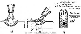
Formation of a welded joint
When heated by a burner flame, local melting of the metal of the connected parts occurs. The molten metal of the edges together with the metal of the additive forms a weld pool. Its boundaries are defined by solid metal. Liquid metal wets the edges of parts, removes the film covering them, and creates the possibility of the manifestation of interatomic interaction forces.
During the welding process, the gas flame moves along the edges of the parts being joined, and the weld pool moves with it. As a result of sequential cooling and solidification of the weld pool metal, a welded joint is formed.
The volume of the weld pool is small compared to the volume of the parts being joined, so intense heat removal occurs. To maintain the metal of the weld pool in a liquid state and the normal course of the welding process, it is necessary that the heating source have a high temperature and have high thermal power. In oxy-acetylene welding, only 10% of the total thermal power of the flame is spent on useful heating of the metal, the rest is spent on compensating for various heat losses.
Metallurgical processes occurring in the weld pool
The liquid metal of the weld pool comes into contact with gases and slags formed as a result of oxidation of the surface layers of the metal. Oxygen and nitrogen enter the weld pool from the air. Oxygen can also come from the gas mixture supplied by the burner. Hydrogen comes mainly from the flame, as well as as a result of the interaction of some metals with moisture during the decomposition of water vapor or hydrocarbons that are part of the contaminants remaining on the edges of parts after they are cleaned before welding.
The interaction of gases with the metal of the weld pool can be different. For example, oxygen actively combines with metals such as aluminum Al, magnesium Mg and copper Cu. Nitrogen does not interact with copper and aluminum.
During gas welding, the molten metal of the weld pool is actively affected by the gas flow of the middle zone of the flame containing carbon monoxide CO, hydrogen H2, water vapor H2O, carbon dioxide CO2, atomic hydrogen H, oxygen O2 and nitrogen N2. In the middle zone of the flame, it is also possible to have a small amount of free carbon C, which has not had time to completely oxidize into carbon monoxide CO at the boundary of the flame core.
The nature of the reactions that occur in the weld pool is determined by the composition of the middle zone of the flame, which depends on the ratio of gases in the combustible mixture. The remaining reactions of the weld pool are oxidation and reduction reactions.
The metal that melts during the welding process undergoes the greatest changes. At the same time, the content of impurities and alloying additives in the metal changes, it can be enriched with oxygen, and under certain conditions - with hydrogen, nitrogen and carbon. Thus, when welding steel, which is an alloy of iron Fe with carbon with manganese Mn, silicon Si, sulfur S, phosphorus P present in the form of impurities and additives, the scheme of interaction of substances in the liquid metal of the weld pool has the form shown in Fig. 6.
The rate of formation of oxides in the surface layer of liquid metal is very high. The oxides in the weld pool interact with the molten metal. To prevent or weaken the oxidation process, deoxidizing agents are introduced into the weld pool as part of fluxes and filler material, i.e. substances that have a greater affinity for oxygen compared to the metal of the weld pool. Carbon, carbon monoxide and hydrogen coming from the burner flame are used as deoxidizers. For non-ferrous metals, the burner flame does not provide deoxidation, so it is necessary to use flux.
Rice. 6. Scheme of the interaction of substances in the molten metal of the weld pool
Hydrogen affects the formation of pores in the weld. Its solubility in liquid and solid metal differs. The solubility of hydrogen in liquid aluminum is higher than in solid aluminum, therefore, when the weld metal solidifies, gas bubbles are released that need to be released into the atmosphere. Otherwise, for example, when the bath quickly solidifies, the gas remains in the metal, forming pores. The presence of hydrogen also leads to the occurrence of residual stresses in the metal. In this case, the plastic properties of the metal are reduced and brittle fracture may occur.
Not only gases, but also slags interact with the molten metal of the weld pool. Typically, slag is located on the surface of the weld pool, since its density is less than the density of the molten metal.
The chemical properties of slag are determined by the nature of the oxides that make up the slag. Depending on the predominant content of certain oxides, slags can be acidic or basic.
It is desirable that the slags formed during gas welding quickly harden, have low viscosity and density, high gas permeability and weak adhesion to the weld metal in the solid state. Otherwise, slag particles remaining in the weld metal reduce its strength and corrosion resistance. Gases do not have time to escape from the weld pool, which leads to the formation of pores and makes it difficult to remove slag residues from the surface of the weld, and ultimately deteriorates the quality of the product.
As the welding torch moves, the previously molten weld pool begins to cool. Metal crystallization occurs in it; in this case, the growth of columnar crystals either slows down or stops, so the weld metal has a columnar and layered (scaly) structure.
4.2. Types of flame
Depending on the ratio between oxygen and acetylene, three main types of welding flame are obtained:
- normal;
- oxidative;
- carburizing
Depending on the type of material being welded, the welding flame is adjusted as follows:
| Metal to be welded | Carburizing flame | Normal flame | Oxidizing flame |
| Steel | — | + | — |
| Cast iron | + | 0 | — |
| Copper | — | + | — |
| Brass | — | — | + |
| Aluminum | + | 0 | + |
Table 6. Selecting the type of welding flame (18)
“+” - welds well; 0—possible; “-“ - poorly welded
Normal flame
A normal flame is obtained when slightly more, from 1.1 to 1.3 volumes of acetylene, is supplied to the burner per volume of oxygen. A normal flame is characterized by the absence of free oxygen and carbon in the reduction (working) zone.
A little more oxygen is supplied to the burner due to its low contamination and the consumption of hydrogen combustion. In a normal flame, all three zones are clearly visible.
Rice. 60. Structure of a normal flame (18)
Oxidizing flame
An oxidizing flame is produced when there is an excess of oxygen, when more than 1.3 volumes of oxygen are supplied to the burner per volume of acetylene. In this case, the core acquires a cone-shaped shape, is significantly reduced in length, becomes less sharp in outline and acquires a paler color. The working area and torch are also reduced in length. The entire flame takes on a bluish-violet color. The flame burns with noise, the level of which depends on the oxygen pressure. The temperature of the oxidizing flame is higher than the temperature of the normal flame. The oxidizing flame can be used in brass welding and brazing.
Such a flame strongly oxidizes the metal being welded, which leads to a brittle and porous weld and burnout of useful impurities of silicon and manganese. You can use an oxidizing flame when welding steels, but it is necessary to use filler wire, which has a high content of manganese and silicon, which are deoxidizing agents.
Rice. 61. Structure of the oxidizing flame (18)
Carburizing flame
A carburizing flame is produced when there is an excess of acetylene, when 0.95 or less volumes of oxygen are supplied to the burner per volume of acetylene. The core of such a flame loses the sharpness of its outline, and a green rim appears at its end, which is used to judge the excess of acetylene. The working area is much lighter and almost merges with the core, and the torch acquires a yellowish color. With a greater excess of acetylene, the flame begins to smoke, since there is a lack of oxygen necessary for complete combustion of acetylene. Black flakes of soot fly around the welding area. Excess acetylene decomposes into hydrogen and carbon. The carbon goes into the weld metal, so the acetylene flame will carbonize the weld metal.
The temperature of the carburizing flame is lower than that of the oxidizing and normal flames.
Rice. 62. Structure of the carburizing flame (18)
Rice. 63. Carburizing flame. Photo by the author
www.e-ope.ee
Structural transformations in the weld and heat-affected zone
Under the influence of the heat of the burner flame, the metal of the weld pool melts and the base metal adjacent to its boundaries is heated. That part of the base metal, the structure of which changes when heated, is called the heat-affected zone (HAZ) or heat-affected zone.
Rice. 7. Welded connection diagram : 1 - seam; 2 - thermally affected zone; 3 - base metal
Various sections of the HAZ are heated from a temperature close to the melting temperature (near the boundary of the weld pool) to the temperature at which structural transformations begin (near the boundary of the base metal that has not been heated).
The welded joint (Fig. 7) consists of weld 1, formed as a result of crystallization of the weld pool, HAZ 2 and base metal 3, which was not exposed to heating. Depending on the nature of the structural changes, the HAZ can be divided into separate sections (Fig. 8).
Rice. 8. Scheme of the structure of the heat-affected zone during gas welding of low-carbon steel : I - area of incomplete melting; II - overheating area; III - normalization section; IV - area of incomplete recrystallization; V—recrystallization area; VI - area of blue brittleness
Near the seam there is an area of incomplete melting (fusion boundary). This is followed by an overheating section (a section of complete recrystallization), in which the metal is heated to the temperature of formation of the liquid phase. This section is characterized by a coarse-grained structure and, during gas welding, has a significant length of about 21 ... 23 mm from the weld boundary. Next comes the normalization section, which has a length of about 4 ... 5 mm. This is followed by a section of incomplete (partial) recrystallization, which passes into the base metal. The length of the section of incomplete recrystallization is 2 ... 3 mm, and the total length of the HAZ during gas welding of steel is on average 27 ... 30 mm.
Increasing the number of the torch tip leads to an increase in the length of the HAZ. As the welding speed increases, the HAZ dimensions decrease.
7.1. Welding flame
During gas welding, various processes occur: physical, associated with heating and melting of the metal, formation of a weld, as well as chemical, caused by combustion, interaction of flux and filler material with the molten metal.
The main tool of a gas welder is a welding flame. It is formed when a flammable gas burns in oxygen. The ratio of the volumes of oxygen and combustible gas in their mixture determines the appearance, temperature and nature of the influence of the welding flame on the molten metal.
Let's consider the structure of the flame (Fig. 7.1). The welding flame has three clearly distinguishable areas: core 7, reduction zone 2 and torch 3.
Rice. 7.1. The structure of an acetylene welding flame and the temperature distribution along the length of the torch: 1 - core; 2 - recovery zone; 3 - torch
core is a brightly luminous zone, in the outer layer of which hot carbon particles formed during the decomposition of acetylene burn.
The reduction zone , darker, consists of carbon monoxide and hydrogen, which deoxidize the molten metal, removing oxygen from its oxides.
The torch - the peripheral part of the flame - is a zone of complete combustion of hydrocarbons in ambient oxygen.
Depending on the ratio of the volumes of oxygen and acetylene, three main types of welding flame are obtained: normal, oxidizing and carburizing (Fig. 7.2).
Rice. 7.2. Types of welding flame: a - normal; b - oxidative; c - carburizing; 1 - core; 2 - recovery zone; 3 - torch
A normal welding flame is formed when there is one volume of acetylene in the torch for one volume of oxygen. In a normal flame, all three zones are clearly visible.
The core has a sharply defined shape, close to a cylinder with a brightly glowing shell. The core temperature reaches 1000 °C.
Welding is carried out in the reduction zone containing products of incomplete combustion of acetylene. The temperature of this zone at a point 3.6 mm from the core is 3150°C. The torch has a temperature of 1200.2500 °C.
A normal welding flame is used to weld all grades of steel, copper, bronze and aluminum.
An oxidative welding flame is obtained with an excess of oxygen, when more than 1.3 volumes of oxygen are supplied to the torch per volume of acetylene. The core of such a flame has a shortened, cone-shaped shape. It takes on less sharp outlines and a paler color than a normal flame. The length of the reduction zone decreases compared to a normal flame. The torch has a bluish-violet color. Combustion is accompanied by noise, the level of which depends on the oxygen pressure. The temperature of an oxidizing flame is higher than that of a normal flame, but when welding with such a flame, due to excess oxygen, porous and brittle seams are formed.
Oxidizing flame is used in brass welding and brazing.
A carburizing welding flame is obtained with an excess of acetylene, when in the torch there is no more than 0.95 volume of oxygen per volume of acetylene. The core of such a flame loses its sharp outline, and a green rim appears at its end, the presence of which indicates an excess of acetylene. The reduction zone is significantly lighter than that of a normal flame and almost merges with the core. The torch becomes yellow in color. With a significant excess of acetylene, the flame becomes smoky. The temperature of the carburizing flame is lower than that of the normal and oxidizing flames.
Cast iron is welded using a lightly carburizing flame and hard alloys are deposited.
The gas welder adjusts and sets the type of welding flame “by eye”.
When performing welding work, it is necessary that the welding flame has a thermal power sufficient to melt the metal being welded.
The flame power during gas welding depends on the acetylene flow rate - the volume of gas passing through the torch in one hour. The power is adjusted by selecting the burner tip and changing the position of the acetylene valve. The flame power is selected in accordance with the thickness of the metal being welded and its thermophysical properties.
The acetylene consumption, dm 3 /h, required to melt a 1 mm thick layer of welded metal is established in practice. Thus, a layer of low-carbon steel 1 mm thick is melted at an acetylene consumption of 100.130 dm 3 /h. To determine the acetylene consumption when welding a specific part, you need to multiply the consumption corresponding to a unit thickness by the actual thickness of the metal being welded, mm.
Example. When welding low-carbon steel 3 mm thick, the minimum acetylene consumption, dm 3 / h, will be 100x3 = 300, and the maximum - 130x3 = 390.
Stress and Strain
As a result of less concentrated heat input compared to arc welding, the heated metal during gas welding has a larger volume than during arc welding. This, first of all, leads to a significant increase in temporary deformations that occur during the welding operation itself.
Temporary deformations in some cases become so significant that they interfere with the normal conduct of the welding process. For example, the edges to be welded diverge over significant distances. In these cases, when welding thin sheet metal butt and overlap during the welding process itself, it is necessary to apply straightening with local pressure or impacts.
The development of deformations over time occurs ahead of the completion of the seam itself, and therefore the elements connected by welding receive irreversible distortions. Added to the deformations during subsequent cooling, the general residual deformations after gas welding lead, as a rule, to a greater distortion of the shape of the welded joints than in arc welding. The use of rigid fastening of elements before gas welding in many cases does not give the desired result, since fastening outside the seam when heated leads to plastic compression in a significant area near the seam, which can even increase
read deformation. When fastening near the welded edges, large plastic deformations obtained during the heating process can lead to destruction of the welded joint during cooling.
Gas welding of insufficiently rigid welded structures often does not allow obtaining products of the required shape.
When gas welding seams in rigid contours, the possibility of cracks increases due to a larger area of plastic deformation of the metal in the heating zone.
Preheating flame for gas cutting
Oxygen (gas) cutting is a process of intense oxidation of metal in a certain volume, followed by removal of liquid oxide with a jet of oxygen. The cutting process begins with heating the upper edge of the metal with a preheating flame to the ignition temperature of the metal in oxygen, which, depending on the chemical composition of the steel, is 1,050 ... 1,200 ° C. When the ignition temperature is reached at the upper edge of the metal, a stream of oxygen is supplied to it from the cutting nozzle; in this case, the steel begins to burn in a stream of oxygen with the formation of oxides and the release of a significant amount of heat, which ensures the heating of the steel near the upper edge to the melting point. The melt of liquid oxides and iron formed on the upper part of the edge moves along the side edge of the metal with a stream of oxygen and heats the lower layers of the metal, which are successively oxidized until all the metal is cut to its full depth. At the same time, the cutter begins to move at a certain speed in the cutting direction. A continuous layer of burning metal is formed on the frontal surface of the cut over its entire thickness. The oxidation of the metal at each moment of time begins from the top and is successively transmitted to the lower layers of the metal.
For the oxygen cutting process to proceed, the following conditions must be met:
- contact between a stream of oxygen and liquid metal;
- heating unoxidized metal to ignition temperature;
- the release of a certain amount of heat by combustion products, sufficient to create a layer of molten metal on the cut surface;
- sufficient viscosity of the liquid melt to create the possibility of mixing the liquid metal with a stream of oxygen.
The above conditions determine the requirements for metal processed by oxygen cutting. First of all, the melting point of the oxides must be lower than the melting point of the metal itself. Otherwise, the oxygen stream will not be able to oxidize the molten metal.
If the ignition temperature of the metal is higher than the melting temperature, the metal will begin to melt and be blown out by a stream of oxygen without subsequent oxidation (“melting process”). This process requires significant energy costs. When the heat of oxide formation is low, the frontal surface of the cut does not warm up to the melting temperature, and the cutting process is interrupted. For the same reasons, the metal’s ability to undergo oxygen cutting is negatively affected by its high thermal conductivity.
The high viscosity of the melt does not ensure its movement in the surface layers, resulting in reduced heat generation at the cutting edge.
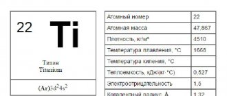
Among pure metals, iron and titanium are well processed by oxygen cutting. Nickel, copper, aluminum, magnesium, chromium and zinc cannot be cut using conventional oxygen methods.
The preheating flame serves to heat the surface layers of the metal to the ignition temperature. In oxy-fuel cutting, gaseous and liquid hydrocarbons are used as fuel. When flammable substances burn in a mixture with oxygen, a high-temperature flame is formed. Acetylene provides the highest flame temperature. Acetylene is an expensive gas because the production of the initial product for its production - calcium carbide - requires high energy consumption. As a result, acetylene is rarely used in oxy-fuel cutting today. For these purposes, substitute gases are used: natural gas, propane or propane-butane mixtures, etc.
The process of heating a metal with a gas flame occurs in two stages. At the first stage, the metal edge is heated to the ignition temperature in a stream of oxygen with a stationary heat source. The heating time to a given temperature depends on the power of the heat source, the thermophysical properties of the material and its mass. With increasing thickness of the metal being cut, it is necessary to increase the consumption of combustible gas. The transition to a flammable gas with a lower calorific value compared to acetylene requires an increase in its consumption. An increase in flammable gas consumption is also necessary if the metal surface is covered with various contaminants (scale, burnt marks) or the distance between the surface of the metal being cut and the cutter is increased for technological reasons.
At the second stage of the process, the preheating flame heats the underlying surface layers of the metal to the ignition temperature, which ensures continuity of the process. At the first stage of the process, as a rule, a flame with an excess oxygen content is used, which ensures accelerated heating of the edge. During the cutting process, the metal is heated with a flame of normal composition.
A mixture of flammable gas and heating oxygen comes out of special holes in the mouthpieces, located in a certain way in relation to the outlet of the cutting oxygen. For hand-held and machine cutters, a concentric arrangement of outlet holes is used in relation to the cutting nozzle. In hand-held torches, the flame emerges from a gap formed by the outer surface of the inner nozzle and the inner surface of the outer nozzle.
Gas welding
In gas welding, the diagram of which is shown in Fig. 3.15, blanks 1
and the filler material
2
in the form of a rod or wire is melted with a high-temperature flame
4
of a gas burner
3
.
A gas flame is produced by the combustion of flammable gas in an atmosphere of technically pure oxygen . The flame power is adjusted by changing the burner tips.
Rice. 3.15. Gas welding diagram
Heating of the workpiece is carried out more smoothly than with arc welding , therefore gas welding is used for welding: metal of small thickness (0.2–5 mm); low-melting non-ferrous metals and alloys; metals and alloys requiring gradual heating and cooling (tool steels, brass); for welding defects in cast iron and bronze castings. As metal thickness increases, productivity decreases and deformation increases.
Rice. 3.13. Electroslag welding diagram
Weldable workpieces 1
installed in a vertical position
.
Flux is poured
into the closed space between the water-cooled copper slides 4 7
using a special feed mechanism
6
.
At the beginning of the process , an arc is excited, the flux melts and electrically conductive slag is formed 5
.
The slag bypasses the arc, it goes out , the output circuit of the power source is closed through the slag . The current passing through the slag heats it up, this leads to melting of the edges of the base metal and the electrode. The melt flows down and forms a weld pool
8 , squeezing the slag upward and solidifies
.
Defects form in the initial and final sections of the seam : at the beginning of the seam - lack of penetration of the edges, at the end of the seam - shrinkage cavity and non-metallic inclusions. Therefore, welding begins and ends on special strips 2
and
3
, which are then removed by gas cutting.
Advantages of the method: welding of metal of any thickness is possible (starting from 16 mm). Workpieces up to 150 mm thick can be welded with one electrode that oscillates transversely in the plane of the joint . When the workpiece thickness is more than 150 mm, several wires are used. I have experience in welding metal up to 2 m thick.
The disadvantage of this method is the formation of large grains in the weld and heat-affected zone due to slow heating and cooling. It is necessary to carry out heat treatment: normalization or annealing to refine the grain.
Electroslag welding is widely used in heavy engineering for the manufacture of forged-welded and cast-welded structures : these are frames and parts of powerful presses and machine tools, crankshafts of marine diesel engines, rotors and shafts of hydraulic turbines, high-pressure boilers, etc.
3.2.8.1. Gases used in welding
(containing approximately 94% CH4), oil and gas, gasoline and kerosene vapors can be used as flammable gases in welding production : when burned in technically pure oxygen, it gives the highest flame temperature (3150 °C) and releases the greatest amount of heat (11470 kcal/m3). Acetylene is lighter than air and oxygen. When the air contains 2.8–80% C2H2, an explosive mixture is formed . Acetylene ignites at 420 °C, becomes explosive when compressed above 0.18 MPa , as well as upon prolonged contact with copper and silver.
Acetylene is obtained from calcium carbide by reacting the latter with water. The reaction proceeds with the release of a significant amount of heat:
CaC2 + 2H2O = C2H2 + Ca(OH)2
Acetylene for welding comes from the generator in which it is produced, or from metal cylinders. In the cylinders, acetylene is mixed with acetone under a pressure of 1.5−1.6 MPa. For safety, an acetylene cylinder is filled with charcoal, which creates a system of capillary vessels.
Technical oxygen (98.5–99.5%) is supplied to the welding stations through pipelines at a pressure of 0.5−1.6 MPa or from cylinders at a pressure of up to 15 MPa. To reduce the oxygen pressure at the outlet of the cylinder and maintain the pressure constant during operation, gas reducers are used : they reduce the pressure from 15 to 0.1 MPa. Acetylene reducers reduce pressure from 1.6 to 0.02 MPa.
From the cylinder reducers, oxygen and flammable gas are supplied separately to the welding torch, which is designed to properly mix oxygen with flammable gas, supply the flammable mixture to the welding site and create a concentrated flame of the required power.
Based on the principle of operation, burners are divided into injection (suction) low gas pressure and non-injector medium and high pressure. There are single- and multi-flame burners.
Rice. 3.16. Gas burner diagrams: a
– injection;
b
– non-injector
Oxygen to the injector (Fig. 3.16, a
) enters through the valve through a hose at a working pressure of 0.1–0.5 MPa.
Flowing at high speed from the injector into the mixing chamber, the oxygen stream creates a vacuum that ensures the suction of acetylene.
Acetylene under low pressure (0.001–0.05 MPa) flows through a hose and then through the burner body into the mixing chamber, where it is mixed with oxygen. The resulting combustible mixture enters the mouthpiece. Upon exiting it, the mixture burns, forming a welding flame. Non-injector burner (Fig. 3.16, b
) operates at acetylene pressures of more than 0.05 MPa and oxygen pressures of up to 0.5 MPa.
When igniting the burner, first open the oxygen valve a quarter turn, then open the acetylene valve and ignite the gas mixture coming out of the tip.
3.2.8.2. Welding acetylene-oxygen flame
The structure, temperature and influence of the welding flame on the molten metal depend on the ratio of oxygen and acetylene in the combustible mixture.
The combustion of acetylene can be represented by the following reaction, which occurs in two stages:
C2H2 + 2.5O2 = 2CO2 + H2Opar
In the first stage, one volume of acetylene and one volume of oxygen (C2H2 + O2 = 2CO + H2) are supplied to the burner.
In the second stage, due to oxygen in the surrounding air, the reaction occurs
2CO + H2 + 1.5O2 = 2CO2 + H2O
Depending on the ratio of oxygen and acetylene in the initial combustible mixture, three types of oxygen-acetylene flame are distinguished :
• neutral
, or
normal reducing flame at
a ratio of O2: C2H2 = 1: 1.2. Most metals and alloys are welded with this flame;
• carburizing flame
at a ratio of O2:C2H < 1
, i.e., with an excess of acetylene. In this case, the flame core lengthens compared to the core of a normal flame, and the flame loses its sharp outline .
This flame is used in welding cast iron and surfacing high-speed steels and hard alloys; • oxidizing flame at a ratio of O2 : C2H2 > 1.2, i.e., with an excess of oxygen. At the same time, the flame acquires a bluish tint, and the size of the flame core decreases. This flame is used when welding brass.
In Fig. Figure 3.17 shows a diagram of the structure of a normal welding flame formed during the combustion of acetylene . The flame consists of three zones: core 1
, reducing zone
2
and oxidizing zone
3
. The flame core has the shape of a truncated cone with a rounded end. This part of the flame consists of a mixture of oxygen and hot decomposition products of acetylene and oxygen (the brightest part of the flame).
Rice. 3.17. Scheme of the structure of a normal acetylene-oxygen flame and a graph of temperature distribution along its length
In the reduction zone, heat is released mainly due to the oxidation of hot carbon particles into carbon monoxide. The highest temperature in this zone (up to 3150°C) is created at a distance of 3−5 mm from the end of the flame core. This zone has a characteristic bluish glow.
The combustion products of acetylene, CO and H2, located in the reduction zone, heat and melt the metal. They can also reduce oxides, including iron oxides formed during welding.
In the oxidation zone, with an excess of oxygen in the air, CO burns out into CO2 and H2 into H2Ovapor. This part of the flame is yellowish in color with a red tint. The gaseous products of this zone have oxidizing properties, but they prevent contact of the molten metal with air.
Cutting oxygen jet
The jet of cutting oxygen serves as a tool; the quality of the cut surface and cutting performance largely depend on its properties. One of the main requirements for a cutting oxygen jet is that it must maintain its geometric dimensions throughout the entire thickness of the metal being cut.
When gas flows from the nozzle into the atmosphere, the jet at a certain distance from the nozzle retains its parameters (speed, stagnation temperature) equal to the values at the exit of the jet from the nozzle. Propagating further, the jet captures particles of the environment (air), as a result of which a turbulent boundary layer is formed around the zone with constant parameters, the thickness of which increases as the jet moves away from the nozzle. As a result, the jet of cutting oxygen expands as it moves away from the nozzle and at the same time its speed decreases, thereby reducing the purity of the oxygen.
Rolled steel with a thickness of 5 ... 8 mm is processed at a cutting oxygen pressure in front of the cutter of 392 ... 1,176 kPa. For cutting steel castings and forgings of large thickness (more than 300 mm), low oxygen pressure (up to 392 kPa) is used when cylindrical-type cutting oxygen nozzles are used in the mouthpieces.
An important parameter of the cutting jet is the speed of its flow from the nozzle. When using oxygen cutting, it is considered most favorable to obtain maximum oxygen flow rates at the outlet, and the static pressure in the jet at the nozzle exit should not differ from atmospheric pressure.
Excess pressure at the exit compared to atmospheric pressure leads to expansion of the gas jet at the exit of the nozzle. This reduces the kinetic energy of the jet and worsens its cutting properties.
Increasing the flow rate of cutting oxygen increases the degree of dynamic impact on the liquid metal film, which ensures an increase in the speed of oxygen cutting, all other things being equal (Fig. 9). Therefore, high pressure oxygen should be used for cutting. In addition to a certain volume of oxygen supplied to oxidize the metal, an additional amount of oxygen must be supplied to the cutting zone to blow liquid slag out of the cutting gap. The practice of oxygen cutting shows that the oxygen utilization rate is determined mainly by the requirements for the quality of the cut surface and the thickness of the metal. The oxygen utilization coefficient has the lowest values (0.2 ... 0.4) when cutting metal with a thickness of 5 ... 10 mm, and with an increase in thickness to 100 mm it increases approximately 2 times and then changes insignificantly.
Rice. 9. Dependence of cutting speed vр on oxygen flow rate w for steel thickness of 20 mm (1) and 100 mm (2)
The purity of the oxygen in the cutting jet has a significant influence on the oxygen cutting process. Since the oxygen jet is used not only to oxidize the metal, but also to blow oxides out of the cut, in the lower part of the cut the concentration of impurities in oxygen increases significantly. With an oxygen utilization factor of 0.5, the amount of inert impurities in the oxygen stream increases by 2 times. The penetration of oxygen particles through the layer of inert impurities is hindered, and the oxidation reaction slows down. When cutting with oxygen of reduced purity, a large amount of difficult-to-remove burr appears on the lower edges. In this case, to obtain the required quality of the cut surface, it is necessary to reduce the cutting speed. Modern installations for oxygen production provide high purity of oxygen - not lower than first grade (99.2%). Currently, the lower limit of oxygen purity used for oxyfuel cutting is limited to 98%.
Welding flame
PROPERTIES AND CONTROL OF WELDING FLAME
The appearance, temperature and influence of the welding flame on the molten metal depend on the composition of the combustible mixture, i.e. the ratio of oxygen and acetylene in it.
When acetylene burns in air without the addition of oxygen, a yellowish flame is formed, shaped like a long torch without a light core. Such a flame has a low temperature and smokes, releasing a lot of soot (unburned carbon), and is therefore unsuitable for welding.
If oxygen is added to the flame, it dramatically changes its color and shape, and its temperature increases significantly. By changing the ratio of oxygen and acetylene, it is possible to obtain three main types of welding flame (Fig. 84, a, b, c): normal, also called reducing; oxidizing (with excess oxygen) and carburizing (with excess acetylene).
For welding most metals, a normal (reduction) flame is used. Theoretically, it is formed when one volume of oxygen is supplied to the burner for one volume of acetylene. Acetylene then burns due to the oxygen in the mixture according to the reaction
Subsequent combustion occurs due to oxygen in the surrounding air according to the reaction
Carbon monoxide and hydrogen formed in the flame during phase I of combustion deoxidize the metal, reducing the oxides present in the weld pool. In this case, the weld metal is obtained without pores, gas bubbles and oxide inclusions.
In practice, slightly more oxygen is supplied to the mixture than is necessary to obtain a reduction flame according to the above combustion scheme. A normal reducing flame is obtained when an excess of oxygen in the mixture is up to 30% compared to theoretical, i.e., when the ratio of acetylene and oxygen is from 1: 1 to 1: 1.3.
The formation diagram of a normal reducing acetylene-oxygen flame is shown in Fig. 85, a. A normal flame has a core, a reduction zone and a torch. The core has a clearly defined shape, close to the shape of a cylinder with a rounded end, and a brightly glowing shell of hot carbon particles, the combustion of which occurs in the outer layer of the shell. The dimensions of the core depend on the flow rate of the combustible mixture and its flow rate. If you increase the oxygen pressure in the burner, the flow rate of the mixture will increase and the core will lengthen. As the mixture flow rate decreases, the core shortens. In Fig. 85, and below are the lengths and diameters (mm) of the nuclei of acetylene-oxygen flame obtained in mouthpieces of different numbers.
The reduction zone is dark in color, distinguishing it from the core and the rest of the flame. The length of this zone reaches 20 mm from the end of the core, depending on the number of the mouthpiece. It contains carbon monoxide and hydrogen. The reduction zone has the highest temperature at a point 2-6 mm from the end of the core. This part of the flame heats and melts the metal during the welding process.
The rest of the flame beyond the reduction zone is called the torch. The torch contains carbon dioxide, water vapor and nitrogen, which are formed during the combustion of carbon monoxide and hydrogen in the reduction zone due to the oxygen of the surrounding air, which includes nitrogen. The flame temperature is significantly lower than the temperature of the reduction zone.
If you increase the oxygen supply or reduce the acetylene supply to the burner, you get an oxidizing flame. It is formed when the mixture contains more than 1.3 volumes of oxygen per volume of acetylene. The oxidizing flame is characterized by a shortened, pointed core with less sharp outlines. The temperature of the oxidizing flame is higher than the temperature of the normal reducing flame, but such a flame can oxidize the metal being welded.
Reducing the oxygen supply or increasing the acetylene supply produces a carburizing flame, which is sometimes called an acetylene flame. It is formed when 0.95 or less volume of oxygen per volume of acetylene is supplied to the burner. In an acetylene flame, the size of the combustion zone increases, the core loses its sharp outline, becomes blurry, and a green rim appears at the end of the core, which indicates an excess of acetylene. The reduction zone is lighter, almost merges with the core and the flame takes on a yellowish color. With a large excess of acetylene, the flame smokes due to the lack of oxygen necessary for complete combustion of acetylene.
Excess acetylene in an acetylene flame decomposes into hydrogen and carbon and turns into molten metal. The temperature of such a flame is lower than the temperature of the reduction flame. By reducing the supply of acetylene to the burner (until the green rim at the end of the core completely disappears), the acetylene flame is converted into a normal one.
When adjusting the flame, pay attention to the correct setting of the oxygen pressure and the size of the flame core. With increasing oxygen pressure, the rate of flow of the mixture from the mouthpiece increases and the flame becomes “hard,” i.e., it inflates the metal of the weld pool and thereby makes welding difficult. If the flow rate of the mixture is too high, the flame may come off the mouthpiece. If the oxygen pressure is too low, the flame becomes shorter and the burner begins to clap as the end of the mouthpiece approaches the metal.
The welding flame must have sufficient thermal power, i.e., provide the amount of heat necessary to melt the welded and filler metal and cover heat loss to the environment. The thermal power of the flame is determined by the flow rate of acetylene (dm 3 / h) in the burner.
When welding, the thermal power of the flame is selected depending on the thickness, the metal being welded and its physical properties. A metal that is thick and conducts heat well requires a more powerful welding flame than a thin, less thermally conductive and more fusible metal. By changing the thermal power of the flame, it is possible to widely regulate the rate of heating and melting of the metal, which is one of the positive qualities of the gas welding process. The diagram and temperature distribution for methane-oxygen and propane-butane-oxygen flames are shown in Fig. 85, b.
METALLURGICAL PROCESSES IN GAS WELDING
Metallurgical processes during gas welding are characterized by: a small volume of the molten metal bath; high temperature and heat concentration at the welding site; high speed of metal melting and cooling; intensive mixing of the bath metal with a gas flow of flame and filler wire; chemical interaction of molten metal with flame gases.
When there is an excess of oxygen in the flame, oxidation reactions of iron, manganese, silicon and carbon occur according to the equations:
The resulting ferric oxide (FeO) can oxidize manganese, silicon and carbon by the reactions:
[Mn] 4- [FeO] = (MnO) + Fe [Si] + 2 [FeO] = (Si02) + 2Fe
Since the oxides MnO and Si02 pass into the slag, the amount of deoxidizing agents (manganese and silicon) in the weld metal decreases. This leads to the appearance of excess oxygen in the deposited metal and deterioration of its mechanical properties.
When carbon monoxide leaves the weld pool, the metal boils and spatters.
If the flame is of a reducing nature, reduction reactions opposite to those given above will occur in the weld pool, namely:
1. Reduction of iron with carbon monoxide:
2. Reduction of iron with hydrogen:
Hydrogen is able to dissolve well in liquid iron. When the weld pool cools quickly, it may remain in the weld in the form of small gas bubbles. However, gas welding provides slower cooling of the metal compared to arc welding. Therefore, when gas welding carbon steel, all the hydrogen has time to separate from the weld metal and the latter becomes dense.
Hydrogen poses a great danger for welding copper and brass, as it can cause “hydrogen disease” (cracking) of copper and porosity of the weld when welding brass.
3. The reduction of iron from its oxide FeO is carried out by manganese and silicon according to the above equations 2 and 3.
If there is excess carbon in the flame, it can pass into the metal and carbonize it through the reactions:
Free carbon is formed in the flame during the decomposition of acetylene according to the reaction C2H2 = 2C + H2.
During gas welding, structural changes occur in the weld metal. Due to slower (compared to arc welding) heating, the zone of influence in gas welding is larger than in arc welding.
When gas welding carbon steels of small thicknesses, the heat-affected zone of the base metal extends by 8-15 mm, and of medium thicknesses by 20-25 mm in either direction from the seam. The nature of the change in the structure of the metal in the heat-affected zone is determined by the composition of the metal (alloy) and its condition before welding. To improve the structure and properties of the weld metal and heat-affected zone, hot weld forging and general or local heat treatment are often used. Local heat treatment is also carried out by heating the weld metal and heat-affected zone with the flame of a welding torch.
Author:
Administration
_ _ _ _ _ _ _ _ _ _ _ _ _ _ _ _ _ _ _ _ _ _ _ _ _ _ _ _ _ _ _ _ _ _ _ _ _ _ _ _ _ _ _ _ _ _ _ _ _ _ _ _ _ _ _ _ _ _ _ _ _ _ _ _ _ _ _ _ _ _ _ _ _ _ _ _ _ _ _ _ _ _ _ _ _ _ _ _ _ _ _ _ _ _ _ _ _ _ _ _ _ _ _ _ _ _ _ _ _ _ _ _ _ _ _ _ _ _ _ _ _ _ _ _ _ _ _ _ _ _ _ _ _ _ _ _ _ _ _ _ _ _ _ _ _ _ _ _ _ _ _ _ _ _ _ _ _ _ _ _ _ _ _ _ _ _ _ _ _ _ _ _ _ _ _ _ _ _ _ _ _ _ _ _ _ _ _ _ _ _ _ _ _ _ _ _ _ _ _ _ _ _ _ _ _ _ _ _ _ _ _ _ _ _ _ _ _ _ _ _ _ _ _ _ _ _ _ _ _ _ _ _ _ _ _ _ _ _ _ _ _ _ _ _ _ _ _ _ _ _ _ _ _ _ _ _ _ _ _ _ _ _ _ _ _ _ _ _ _ _ _ _ _ _ _ _ _ _ _