The reliability, uninterrupted operation and ease of maintenance of a three-phase asynchronous electric motor have been tested by time, millions of users around the world and do not require proof. Moreover, it is the most widespread, accessible and cheapest today. However, not everyone has a 380 V current source. Therefore, let’s look at what it means to connect a three-phase electric motor to a 220 V network, what methods exist for this and what are their main features.
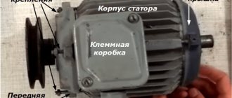
Three-phase electric motor Source ytimg.com
Winding connection options
An asynchronous three-phase electric motor has three windings - for each phase separately - going into the stator slots. However, for the generation of electromotive force and, as a result, rotation of the rotor, they must be connected to each other. It is important to know the connection option for a specific motor. Since this will help you choose the right scheme for connecting it to the 220V network.
Each of the three windings corresponds to its own phase and has both a beginning and an end. In this case, the inputs and outputs are designated by the corresponding letters and numbers:
Range of engines produced during the Soviet Union:
- The first phase is C1-C4.
- Second phase C2-C5.
- Third phase C3-C6.
Designations of modern engines:
- First phase U1-U2.
- Second phase V1-V2.
- Third phase W1-W2.
Connecting the winding of a three-phase motor Source autogear.ru
There are two main circuits for connecting the windings in the type of motor under consideration:
- Star.
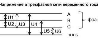
All winding outputs are connected to one point, and the inputs, respectively, to the phases. The schematic representation of this method looks like a star. With this method, a 220V phase is applied to each individual core, and a linear 380V is applied to two consecutive cores.
The main advantage of this scheme is the application of linear current to two wires simultaneously, which significantly reduces inrush currents and allows the rotor to perform a soft start. The downside is lower power due to weak currents in the winding.
- Triangle.
The input of the previous winding is connected to the output of the next one - and so on in a circle. As a result, the diagram resembles a triangle. At a linear voltage of 380V, the currents in the winding will reach a significantly higher value than in the above option. This will make it possible for the motor to exert a significantly greater amount of force. The disadvantage of the circuit is that stronger inrush currents can lead to network overload.
Triangle diagram Source ytimg.com
Good to know! To obtain the advantages of the first and avoid the disadvantages of the second circuit, the connection of the 380 V electric motor and its subsequent acceleration is carried out on the “star”, and then it is automatically switched to the “delta”.
Single-phase asynchronous electric motor
If we leave a short-circuited coil on the rotor and one coil on the stator, we will get an amazing design - an asynchronous single-phase motor.
At first glance, it seems that such an engine should not work. After all, there is no current in the rotor , and the magnetic field of the stator does not rotate. But if you push the rotor by hand in any direction, the engine will start! And it will rotate in the direction in which it was pushed at launch.
The operation of this motor can be explained by imagining the stationary alternating magnetic field of the stator as the sum of two fields rotating towards each other. While the rotor is stationary, these fields balance each other, so a single-phase asynchronous motor cannot start on its own. If the rotor is set in motion by an external force, it will rotate in parallel with one vector and towards the other.
A passing vector will pull the rotor along with it, a counter vector will slow it down.
It can be shown that due to the difference between the head and tail speeds, the influence of the tail vector will be stronger, and the engine will operate in asynchronous mode.
Definition of connection diagram
Before choosing one or another scheme for connecting a motor to 220 V, it is necessary to determine what the connection diagram for its winding is and at what rating it can generally be operated. To do this you need:
- Find and study the technical table on the engine. characteristics .
The information field contains all the important information - designation of the type of connection ∆ - triangle or star - Y , power, number of revolutions, voltage (220 or 380, or 220/380) and the possibility of connecting according to a specific circuit.
- Open the terminal box and verify in practice that the assembled circuit is correct.
The beginning and end of each winding is signed in accordance with the above alphanumeric nomenclature. The user remains to study the connection diagram using jumpers: according to what scheme the connection is made - star or triangle.
Note! If the nameplate (table with information) indicates the Y and only 380V, then when it is connected in a triangle, the winding will burn out. Only professional electricians can upgrade such a 220V motor. Therefore, there is no reason to modify it, especially since today there are many copies that can operate alternatively - both 220 and 380 volts.
Opening the terminal box Source pikabu.ru
See also: Catalog of companies that specialize in electrical work
Types of CD
It is customary to classify these devices according to the type of power supply; depending on this, two groups of CDs are distinguished:
- Direct current. Such machines are characterized by high starting torque, smooth speed control and a relatively simple design.
- Universal. They can operate from both constant and variable power sources. They are distinguished by their compact size, low cost and ease of management.
The first ones are divided into two subtypes; depending on the organization of the inductor, it can be on permanent magnets or special excitation coils. They serve to create the magnetic flux necessary to generate torque. CDs, where excitation coils are used, are distinguished by types of windings, they can be:
- independent;
- parallel;
- consistent;
- mixed.
Having dealt with the types, let's consider each of them.
Universal type CD
The figure below shows the appearance of an electric machine of this type and its main structural elements. This design is typical for almost all CDs.
Design of a universal commutator motor
Designations:
- A is a mechanical commutator, it is also called a collector, its functions were described above.
- B – brush holders, used to attach brushes (usually made of graphite), through which voltage is supplied to the armature windings.
- C – Stator core (made up of plates, the material for which is electrical steel).
- D – Stator windings, this unit belongs to the excitation system (inductor).
- E – Armature shaft.
Connection methods for 220V
To connect a three-phase asynchronous electric motor to a 220-volt network, there are several proven methods:
- With capacitor.
- Without capacitor.
- With reverse.
- Combined star-delta circuit.
Let's look at them in more detail.
Important! When connecting a 380-volt electric motor to a 220-volt network, you need to be prepared to reduce its power to 70% of the factory value. However, in everyday conditions this is quite acceptable and will not affect the performance in any way.
Connecting a 380 V motor to 220 V Source ytimg.com
With capacitor
The most popular and affordable way to initiate 380 volt motors from a 220 V network is a circuit using a capacitor. Its role is to create a phase shift in the windings relative to each other in order to form a rotating magnetic field. If there are three phases, this phenomenon occurs by itself - only one will not force the rotor to rotate. Therefore, the optimal method for connecting an electric motor with 4 wires on one phase is to use a starting winding, in addition to the main winding, in 220V electric motors.
For the 380 V modification, two connection options with a capacitor are possible:
- With working capacitor Cp .
- And parallel connected working Cp and starting capacitor Sp .
In the second case, the engine starts more smoothly and safely. Sp module turns on for a short period of time and turns off as the rotor reaches the required speed. The choice of starting option is largely determined by the degree of rotor load during starting. So, if the start occurs without force, only Cp , and if under load, without free rotation, the presence of Cn .
Connecting a motor with capacitors Source blogspot.com
Connecting a three-phase motor to a single-phase network
The beginnings and ends of the windings (various options) Schemes for connecting a three-phase motor to a single-phase network Asynchronous three-phase motors, namely, due to their widespread use, they often have to be used, consist of a stationary stator and a moving rotor. Winding conductors are laid in the stator slots with an angular distance of 120 electrical degrees, the beginnings and ends of which (C1, C2, C3, C4, C5 and C6) are brought out into the junction box. The windings can be connected according to a “star” (the ends of the windings are connected to each other, the supply voltage is supplied to their beginnings) or “triangle” (the ends of one winding are connected to the beginning of another).
Connecting a three-phase motor according to a triangle diagram
Three-phase motor junction box with jumper positions for delta connection
In the distribution box, the contacts are usually shifted - opposite C1 is not C4, but C6, opposite C2 - C4.
Position of contacts in the junction box of a three-phase motor
Connecting a three-phase motor according to a star circuit
Three-phase motor junction box with jumper positions for star connection
When a three-phase motor is connected to a three-phase network, a current begins to flow through its windings at different times in turn, creating a rotating magnetic field that interacts with the rotor, causing it to rotate. When the motor is turned on in a single-phase network, no torque is created that can move the rotor.
Among the different ways to connect three-phase electric motors to a single-phase network, the simplest is to connect the third contact through a phase-shifting capacitor.
Connecting a three-phase motor to a single-phase network
The rotation speed of a three-phase motor operating from a single-phase network remains almost the same as when it is connected to a three-phase network. Unfortunately, this cannot be said about power, the losses of which reach significant values. The exact values of power loss depend on the connection diagram, engine operating conditions, and the capacitance value of the phase-shifting capacitor. Approximately, a three-phase motor in a single-phase network loses about 30-50% of its power.
Not all three-phase electric motors are capable of working well in single-phase networks, but most of them cope with this task quite satisfactorily - except for the loss of power. Basically, for operation in single-phase networks, asynchronous motors with a squirrel-cage rotor (A, AO2, AOL, APN, etc.) are used.
Asynchronous three-phase motors are designed for two rated mains voltages - 220/127, 380/220, etc. The most common electric motors have an operating voltage of 380/220V windings (380V for star, 220V for delta). More voltage for the “star”, less for the “triangle”. In the passport and on the motor plate, among other parameters, the operating voltage of the windings, their connection diagram and the possibility of changing it are indicated.
Three-phase motor labels
Designation on plate A
indicates that the motor windings can be connected either as a “triangle” (at 220V) or as a “star” (at 380V). When connecting a three-phase motor to a single-phase network, it is advisable to use a delta circuit, since in this case the motor will lose less power than when connected to a star.
Table B
informs that the motor windings are connected in a star configuration, and the distribution box does not provide the ability to switch them to delta (there are only three terminals). In this case, you can either accept a large loss of power by connecting the motor in a star configuration, or, by penetrating the electric motor winding, try to bring out the missing ends in order to connect the windings in a delta configuration.
If the operating voltage of the engine is 220/127V, then the engine can only be connected to a single-phase 220V network using a star circuit. If you connect 220V in a delta circuit, the engine will burn out.
Beginnings and ends of windings (various options)
Perhaps the main difficulty in connecting a three-phase motor to a single-phase network is to understand the wires going into the junction box or, in the absence of one, simply leading out of the motor.
The simplest case is when in an existing 380/220V motor the windings are already connected in a delta circuit. In this case, you just need to connect the current supply wires and the working and starting capacitors to the motor terminals according to the connection diagram.
If the windings in the motor are connected by a “star”, and it is possible to change it to a “triangle”, then this case also cannot be classified as complex. You just need to change the connection diagram of the windings to a “triangle”, using jumpers for this.
Determination of the beginnings and ends of windings
. The situation is more complicated if 6 wires are brought out into the junction box without indicating their belonging to a specific winding and marking the beginnings and ends. In this case, it comes down to solving two problems (But before doing this, you need to try to find some documentation for the electric motor on the Internet. It may describe what wires of different colors belong to.):
- identifying pairs of wires belonging to one winding;
- finding the beginning and end of the windings.
The first task is solved by “ringing” all the wires with a tester (measuring resistance). If you don’t have a device, you can solve the problem using a flashlight light bulb and batteries, connecting the existing wires in a circuit in series with the light bulb. If the latter lights up, it means that the two ends being tested belong to the same winding. In this way, three pairs of wires (A, B and C in the figure below) belonging to three windings are determined.
Determination of pairs of wires belonging to one winding
The second task (determining the beginning and end of the windings) is somewhat more complicated and requires a battery and a pointer voltmeter. Digital is not suitable due to inertia. The procedure for determining the ends and beginnings of the windings is shown in diagrams 1 and 2.
Finding the beginning and end of the windings
To the ends of one winding (for example, A
) a battery is connected, and a pointer voltmeter is connected to the ends of the other (for example,
B
).
Now, if you break the contact of wires A
with the battery, the voltmeter needle will swing in one direction or another.
Then you need to connect a voltmeter to winding C
and do the same operation with breaking the battery contacts.
If necessary, changing the polarity of winding C
and
C2) you need to ensure that the voltmeter needle swings in the same direction, as in the case of winding
B. Winding A
is - with a battery connected to winding
C
or
B.
As a result of all manipulations, the following should happen: when the battery contacts break from any of the windings, an electric potential of the same polarity should appear on the other 2 (the device needle swings in one direction). Now all that remains is to mark the terminals of one bundle as the beginning (A1, B1, C1), and the terminals of the other as the ends (A2, B2, C2) and connect them according to the required circuit - “triangle” or “star” (if the motor voltage is 220/127V ).
Retrieving missing ends
. Perhaps the most difficult case is when the engine has a star connection of the windings, and there is no way to switch it to a delta (only three wires are brought into the distribution box - the beginning of the windings C1, C2, C3) (see figure below) . In this case, to connect the motor according to the “triangle” scheme, it is necessary to bring the missing ends of the windings C4, C5, C6 into the box.
Label of the electric motor being disassembled
Terminal block
To do this, gain access to the motor winding by removing the cover and possibly removing the rotor. The place of adhesion is found and released from insulation. The ends are separated and flexible stranded insulated wires are soldered to them. All connections are reliably insulated, the wires are secured with a strong thread to the winding and the ends are brought out to the terminal board of the electric motor. They determine whether the ends belong to the beginnings of the windings and connect them according to the “triangle” pattern, connecting the beginnings of some windings to the ends of others (C1 to C6, C2 to C4, C3 to C5). The job of bringing out missing ends requires some skill. The motor windings may contain not one, but several solders, which are not so easy to understand. Therefore, if you do not have the proper qualifications, you may have no choice but to connect a three-phase motor in a star configuration, accepting a significant loss of power.
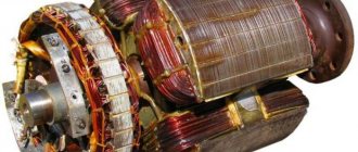
Motor stator
Soldered wires
Soldered wires
Wire output to the terminal box
Connecting wires to the terminal block
Schemes for connecting a three-phase motor to a single-phase network
Delta connection
. In the case of a household network, from the point of view of obtaining greater output power, the most appropriate is a single-phase connection of three-phase motors in a delta circuit. Moreover, their power can reach 70% of the nominal. Two contacts in the distribution box are connected directly to the wires of a single-phase network (220V), and the third is connected through a working capacitor Cp to any of the first two contacts or network wires.
Connecting a three-phase motor to a single-phase network using a triangle diagram
Connecting a three-phase motor to a single-phase network using a triangle diagram
Start-up support
. A three-phase motor without a load can also be started from a working capacitor (more details below), but if the electric motor has some kind of load, it either will not start or will pick up speed very slowly. Then, for a quick start, an additional starting capacitor Sp is required (calculation of the capacitor capacity is described below). The starting capacitors are turned on only while the engine is starting (2-3 seconds, until the speed reaches approximately 70% of the nominal), then the starting capacitor must be disconnected and discharged.
Connecting a three-phase electric motor to a single-phase network using a delta circuit with a starting capacitor Sp
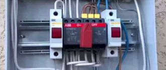
It is convenient to start a three-phase motor using a special switch, one pair of contacts of which closes when the button is pressed. When it is released, some contacts open, while others remain on - until the “stop” button is pressed.
Switch
Reverse
. The direction of rotation of the motor depends on which contact (“phase”) the third phase winding is connected to.
Three-phase motor reverse
The direction of rotation can be controlled by connecting the latter, through a capacitor, to a two-position toggle switch connected by its two contacts to the first and second windings. Depending on the position of the toggle switch, the engine will rotate in one direction or the other.
The figure below shows a circuit with a starting and running capacitor and a reverse button, which allows for convenient control of a three-phase motor.
Connection diagram for a three-phase motor to a single-phase network, with reverse and a button for connecting a starting capacitor
Star connection
. A similar scheme for connecting a three-phase motor to a network with a voltage of 220V is used for electric motors whose windings are designed for a voltage of 220/127V.
Connecting a three-phase motor to a single-phase network using a star circuit
Capacitors
.
The required capacity of working capacitors for operating a three-phase motor in a single-phase network depends on the connection diagram of the motor windings and other parameters. For a star connection, the capacitance is calculated using the formula: Cр = 2800•I/U
For a delta connection:
Cр = 4800•I/U
Where Cp is the capacitance of the working capacitor in microfarads, I is the current in A, U is the network voltage in V. The current is calculated by the formula:
I = P/(1.73•U•n•cosф)
Where P is the electric motor power kW; n - engine efficiency; cosф - power factor, 1.73 - coefficient characterizing the relationship between linear and phase currents. The efficiency and power factor are indicated in the data sheet and on the engine plate. Typically their value is in the range of 0.8-0.9.
In practice, the capacitance value of the working capacitor when connected in a triangle can be calculated using the simplified formula C = 70•Pn, where Pn is the rated power of the electric motor in kW. According to this formula, for every 100 W of electric motor power, about 7 μF of working capacitor capacity is required.
The correct selection of capacitor capacity is checked by the results of engine operation. If its value is greater than required under given operating conditions, the engine will overheat. If the capacitance is less than required, the motor output will be too low. It makes sense to select a capacitor for a three-phase motor, starting with a small capacitance and gradually increasing its value to the optimal one. If possible, it is better to select the capacitance by measuring the current in the wires connected to the network and to the working capacitor, for example, with a current clamp. The current value should be as close as possible. Measurements should be made in the mode in which the engine will operate.
When determining the starting capacity, we proceed, first of all, from the requirements for creating the necessary starting torque. Do not confuse the starting capacitance with the capacitance of the starting capacitor. In the above diagrams, the starting capacitance is equal to the sum of the capacitances of the working (Cp) and starting (Sp) capacitors.
If, due to operating conditions, the electric motor starts without load, then the starting capacitance is usually taken to be equal to the working capacitance, that is, a starting capacitor is not needed. In this case, the switching circuit is simplified and cheaper. To simplify this and, most importantly, reduce the cost of the circuit, it is possible to organize the possibility of disconnecting the load, for example, by making it possible to quickly and conveniently change the position of the engine to loosen the belt drive, or by making a pressure roller for the belt drive, for example, like the belt clutch of walk-behind tractors.
V-belt drive of the Salyut 5 walk-behind tractor
Starting under load requires the presence of an additional capacity (Cn) connected while the engine is starting. An increase in the switchable capacitance leads to an increase in the starting torque, and at a certain value, the torque reaches its maximum value. A further increase in capacity leads to the opposite result: the starting torque begins to decrease.
Based on the condition of starting the engine under a load close to the rated load, the starting capacitance should be 2-3 times greater than the working capacitance, that is, if the capacity of the working capacitor is 80 µF, then the capacitance of the starting capacitor should be 80-160 µF, which will give the starting capacitance (the sum capacity of the working and starting capacitors) 160-240 µF. But if the engine has a small load when starting, the capacity of the starting capacitor may be less or, as stated above, it may not exist at all.
Starting capacitors operate for a short time (only a few seconds during the entire switching period). This allows you to use the cheapest starting electrolytic capacitors, specifically designed for this purpose, when starting the engine (https://www.platan.ru/cgi-bin/qweryv.pl/0w10609.html).
Note that for a motor connected to a single-phase network through a capacitor, operating without load, the winding fed through the capacitor carries a current 20-30% higher than the rated one. Therefore, if the engine is used in an underloaded mode, the capacity of the working capacitor should be reduced. But then, if the engine was started without a starting capacitor, the latter may be required.
It is better to use not one large capacitor, but several smaller ones, partly due to the possibility of selecting the optimal capacitance by connecting additional ones or disconnecting unnecessary ones; the latter can be used as starting ones. The required number of microfarads is obtained by connecting several capacitors in parallel, based on the fact that the total capacitance in a parallel connection is calculated using the formula: Ctotal = C1 + C1 + ... + Cn.
Parallel connection of capacitors
Metallized paper or film capacitors are usually used as workers (MBGO, MBG4, K75-12, K78-17 MBGP, KGB, MBGCh, BGT, SVV-60). The permissible voltage must be at least 1.5 times the mains voltage.
Capacitors
When using the content of this site, you need to put active links to this site, visible to users and search robots.
Literature
Useful tips
Some useful tips on how to connect a 3-wire motor to avoid problems during operation:
- Before starting work, it is recommended to test the engine at idle, if it is functioning properly, then under load.
- If the case becomes very hot, even without load, it is necessary to reduce the capacity of the working capacitor.
- If after starting the motor just hums, but does not rotate the shaft, then you can set it to start manually - by turning the shaft. Next, you can increase the capacity of the starting capacitor.
- When stopping the engine under operating load, the capacity of the working capacitor should be increased.
Helpful information! It is possible to correctly calculate the capacitance of the capacitor only taking into account the power rating of the motor. If there is underload, overheating will occur and the capacity will need to be reduced.
Selection criteria and cost
In order to correctly choose the most suitable type of regulator, you need to have a good idea of what types of such devices there are:
- Various types of control. Can be a vector or scalar control system. The former are used more often, while the latter are considered more reliable.
- The power of the regulator must correspond to the maximum possible power of the motor.
- Based on voltage, it is convenient to choose a device that has the most universal properties.
- Frequency characteristics. The regulator that suits you should match the highest frequency that the motor uses.
- Other characteristics. Here we are talking about the length of the warranty period, dimensions and other characteristics.
Briefly about the main thing
You can connect a 380 to 220 volt electric motor in 4 main ways:
- With capacitor.
- Without capacitor.
- With reverse.
- Star-delta design.
Before starting connection work, it is necessary to determine and verify how the winding is connected in the terminal box, and also find out the necessary characteristics from the technical table. You can perform electrical work if you have experience, but it is better to entrust it to professionals with the appropriate permit.
Operating principle and startup scheme
Principle of operation:
- An electric current generates a pulsating magnetic field on the motor stator. This field can be considered as 2 different fields that rotate in different directions and have equal amplitudes and frequencies.
- When the rotor is stationary , these fields lead to the appearance of moments of equal magnitude, but differently directed.
- If the engine does not have special starting mechanisms , then at start the resulting torque will be zero, which means the engine will not rotate.
- If the rotor is rotated in one direction , then the corresponding torque begins to prevail, which means that the motor shaft will continue to rotate in the given direction.
Launch scheme:
- The launch is carried out by a magnetic field , which rotates the moving part of the motor. It is created by 2 windings: main and additional. The latter is smaller in size and is a launcher. It is connected to the main electrical network through capacitance or inductance. The connection is made only during start-up. In low power motors, the starting phase is short-circuited.
- The engine is started by holding the start button for a few seconds, as a result of which the rotor accelerates.
- When the start button is released , the electric motor switches from two-phase mode to single-phase mode, and its operation is supported by the corresponding component of the alternating magnetic field.
- The starting phase is designed for short-term operation – usually up to 3 s. A longer time under load can lead to overheating, insulation fire and mechanism failure. Therefore, it is important to release the start button in a timely manner.
- In order to increase reliability, a centrifugal switch and a thermal relay are built into the housing of single-phase motors.
- The function of the centrifugal switch is to cut off the starting phase when the rotor reaches its rated speed. This happens automatically - without user intervention.
- The thermal relay turns off both phases of the winding if they heat up above the permissible level.
How else can you connect an electric motor?
By connecting them to the circuit, the engine is launched, which should work correctly.
DC motors DPT The operating principle of such electric machines is based on Faraday's Law for magnetic induction.
Since during the starting process, especially under load, the current increases greatly, the capacitance of the starting capacitor should be three times greater than the operating capacitor. A magnetic field is created that interacts with the rotor winding and causes it to rotate. This is a contactor complemented by auxiliary mechanisms, for example, a thermal relay.
Wires from the windings are routed into it and secured to terminal blocks. Also note that connecting an electric motor with a power of 3 kW or more to conventional wiring is prohibited, as this can lead to the machines turning off or the plugs burning out. Therefore, it is worth considering the situation, for which you can simply reduce the capacity of the installed capacitor bank.
Of course, this is the simplest solution, but at the same time you will immediately receive a sharp reduction in the power of the electric motor. There are two options here: Nominal voltage 3xV - you're in luck and use the circuits above.
Using capacitors for DC voltage in AC networks is highly discouraged due to the fact that capacitors explode. In this case, the capacitance of the starting device will be in the μF range. Simply put, this current will only flow in the motor when it is fully loaded. Type of capacitors What capacitors are used when connecting an electric motor to a volt? As you can see, the voltage is distributed over two series-connected windings, where each is designed for such a voltage.
In this situation, the electric motors are connected correctly according to the star or delta circuit. The stator has special grooves in which the winding is placed, distributed in such a way that the angular distance is degrees. When it is necessary to turn off the power, K1 turns on. This is enough to start the electric motor; Worker, or nominal; Reloading.
It is necessary to look at the motor tag to see what voltage its windings are designed for; it is possible to connect the windings with a star and a triangle. In this situation, the electric motors are connected correctly according to the star or delta circuit. There are three wires sticking out of the electric motor. How to quickly and easily connect a three-phase motor to a single-phase DuMA8819 network
Types of stepper motors according to the type of connection of stator electromagnets:
According to the type of connection of electromagnets, stepper motors are divided into: unipolar and bipolar.
The figure shows a simplified, schematic representation of the windings. In fact, each winding consists of several windings of electromagnets connected in series or parallel
- A bipolar motor has 4 terminals. Pins A and A feed winding AA, pins B and B feed winding BB. To turn on the electromagnet, a potential difference (two different levels) must be applied to the winding terminals, which is why the motor is called bipolar. The direction of the magnetic field depends on the polarity of the potentials at the terminals.
- A unipolar motor has 5 leads. The central points of its windings are connected to each other and are the common (fifth) terminal, which is usually connected to GND. To turn on the electromagnet, it is enough to apply a positive potential to one of the winding terminals, which is why the motor is called unipolar. The direction of the magnetic field depends on which winding terminal the positive potential is applied to.
- A 6-pin motor has taps from the center points of the windings, but winding AA is not connected to winding BB. If you do not use the terminals of the central points of the windings, then the motor will be bipolar, and if these terminals are connected and connected to GND, then the motor will be unipolar.
- The 8-pin motor is the most flexible in terms of connecting electromagnets. This motor can not only be used as bipolar or unipolar, but you can also determine for yourself how to connect the electromagnets of the windings, in series or in parallel.