Marking of metal products and blanks: tools, methods, rules | Construction Bulletin
In the production of metal products, the source material - castings, sheet and profile products - does not correspond in size and shape to the designer's drawing. To cut off excess metal, drill, stamp, weld, or otherwise process a workpiece, key points of the drawing are applied to it. Applying to these points and lines, the processing is carried out.
Basic concept and types of markup
As a rule, unique parts and products produced in small and ultra-small series are marked. For large-scale and mass production, workpieces are not marked; instead, special equipment and control programs are used.
What is markup
The operation of applying the dimensions and shape of a product to workpieces is called marking. The purpose of the operation is to designate the places where the part should be processed and the boundaries of these actions: drilling points, bend lines, weld lines, markings, etc.
Marking is done with points, which are called cores, and lines, which are called risks.
Marks are scratched into the metal surface with a sharp tool or applied with a marker. Cores are filled with a special tool - a center punch.
According to the method of execution, there are such types of markup as:
- Manual. It is made by mechanics.
- Mechanized. Performed using mechanization and automation tools.
Based on the application surface, they are distinguished
- Superficial. It is applied to the surface of the workpiece in one plane and is not associated with the lines and marking points applied to other planes.
- Spatial. It is carried out in a unified three-dimensional coordinate system.
Notes on straightening and marking for thin sheet metal
The choice between surface and spatial markings is determined, first of all, by the complexity of the spatial configuration of the part.
Markup requirements
Plumbing markings must meet the following requirements:
- accurately convey the key dimensions of the drawing;
- be clearly visible;
- not to be abraded or lubricated during mechanical and heat treatment operations;
- do not degrade the appearance of the finished product.
Marking of parts must be carried out with high-quality inventory tools and devices that are subject to periodic verification.
Applying marks
The standard regulates the procedure for drawing marking lines:
- horizontal;
- vertical;
- inclined;
- curvilinear.
Applying curved elements after straight ones provides another opportunity to check their accuracy. The arcs must close the straight lines, the interface must be smooth.
Direct marks are carried out with a well-sharpened scriber, without tearing off, in one step. At the same time, the scriber is tilted away from the ruler or square so as not to introduce distortions.
Parallel lines are drawn using a square and moving it along the reference ruler to the required distance.
If the workpiece already has holes, then a special tool, a center finder, is used to attach marking lines to them.
In order to mark inclined lines, use a marking protractor with a hinged ruler fixed at its zero point.
For particularly precise markings in plumbing, calipers are used. They allow you to measure distances and scratch marks with an accuracy of hundredths of a millimeter.
Marking marking lines
In order to more accurately carry out the risk, cores are placed at its beginning and end. This allows you to visually control the position of the ruler while drawing.
On long-distance risks, auxiliary cores are also placed through
every 5-15 cm.
Circle lines are marked at four points - the ends of perpendicular diameters.
If already treated surfaces are marked, then punching is used only at the beginning and end of the marks.
After finishing, the marks are extended to the side surfaces and the cores are placed on them.
Marking techniques
The following techniques are used in plumbing:
- According to the template. Used in case of small-scale production. The template is made from rolled metal, the entire batch is marked (or even processed) through once marked slots and holes in this sheet. For parts with complex shapes, several templates can be made for different planes.
- Following the example. The dimensions are transferred from the part - the sample. It is used in the manufacture of a new part to replace a broken one.
- Local. Used in the production of complex multi-component products and structures. Blanks are placed on a plane or in space in the order in which they enter the final product and are marked together.
- Pencil (or marker). Used for workpieces made of aluminum alloys so that the scriber does not destroy the passivated protective layer.
- Accurate. It is done using the same methods, but special precision measuring and marking tools are used.
The selection of techniques is carried out in accordance with design and technological instructions.
Marriage during marking
First of all, when marking, defects that were made at previous stages of production emerge. Products from procurement sites or workshops, as well as materials purchased from other enterprises, reveal:
- violation of dimensions
- shape distortion
- warping.
Such castings or rentals are not subject to further marking operations, but are returned to the department or organization that caused the defect to correct it.
At the marking stage itself, defects can be caused by the following factors:
- Inaccurate drawing. The mechanic, without hesitation, displays incorrect dimensions on the part, and during further processing, defective products come out.
- Inaccuracy or malfunction of instruments. All marking tools are subject to mandatory periodic verification by the metrological service of the enterprise or an authorized metrological center.
- Incorrect use of tools or marking accessories. There are known cases when instead of calibrated measuring pads, ordinary pads were used to set the level. In this case, erroneous application of angles and slopes is also possible.
- Inaccurate placement of the workpiece on the marking table or plaza. They lead to distortions when setting aside dimensions, violation of parallelism and coaxiality.
- Wrong choice of reference planes. It is also possible that some of the dimensions were applied from the base planes, and some from the rough surfaces of the workpiece.
Separately among the reasons for defects are the marker's errors. These include:
- Incorrectly read drawing. It is possible to apply a radius instead of a diameter and vice versa, inaccurate application of the centers of holes relative to the center marks, etc. If any difficulties arise, the mechanic must seek clarification from the foreman or foreman.
- Carelessness and inattention when punching and drawing lines.
The human factor, unfortunately, is the most common cause of marking defects.
Negligence can be committed by both the mechanic himself and his supervisors, who did not check the tool on time or issued inappropriate marking devices.
Typically, marking operations are entrusted to the most experienced and responsible workers, counting on the fact that they will not mechanically transfer dimensions from the drawing to the workpiece, but will treat the matter thoughtfully and promptly notice and eliminate the reasons for possible defects on their own or by contacting their managers.
How to level walls using plaster and drywall. Why does the electrode stick when welding? A house with an area of 1 square meter. Our happy future?
Planar marking. Types of markings
Marking is the operation of applying marking lines to the workpiece being processed, defining the contours of the future part or place to be processed. The accuracy achieved with conventional marking methods is approximately 0.5 mm.
Planar marking, usually performed on the surface of flat parts, on strip and sheet material, consists of applying contour parallel and perpendicular lines (scores), circles, arcs, angles, axial lines, various geometric shapes according to given dimensions or contours of various holes according to specified dimensions to the workpiece. templates.
Spatial marking is most common in mechanical engineering; and in its techniques it differs from the planar one.
Devices for planar marking
To carry out markings, marking plates, pads, rotating devices, jacks, etc. are used.
The parts to be marked are installed on the marking plate and all fixtures and tools are placed. The marking plate is cast from fine-grained gray cast iron.
The size of the slab is chosen so that its width and length are 500 mm greater than the corresponding dimensions of the workpiece to be marked. The surface of the stove must always be dry and clean. After work, the slab is swept with a brush, thoroughly wiped with a rag, greased with oil to protect against corrosion and covered with a wooden shield.
Tools for planar marking
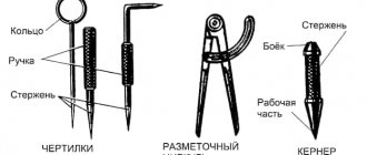
Scribler, caliper, center punch, ruler, square, hammer, etc.
Scribblers are used to draw lines (scores) on the surface to be marked using a ruler, square or template. Scribblers are made from tool steel U10 or U12, sharpened to a cone at an angle of 15-200.
A center punch is a metalworking tool used for making indentations (cores) on pre-marked lines.
Cores are made from tool carbon or alloy steel U7A, U8A, 7HF or 8HF, at an angle of 50-60 degrees.
Compasses are used for marking circles and arcs, dividing segments and circles, as well as for geometric constructions. Compasses are also used to transfer dimensions from measuring rulers to a part.
Calipers . Marking calipers are designed for precise marking of straight lines and centers, as well as for marking large diameters.
Tools for spatial (volumetric) markings.
The same as for planar markings + height gauge.
Reismus is the main tool for spatial marking and is used for drawing parallel, vertical and horizontal lines, as well as for checking the installation of parts on the slab.
Preparing for marking.
Before marking, you must do the following:
— clean the workpiece from dust, dirt, scale, traces of corrosion with a steel brush, etc.;
- carefully inspect the workpiece;
- if cavities, bubbles, cracks, etc. are detected, measure them accurately and, drawing up a marking plan, take measures to remove these defects during further processing (if possible);
— all dimensions of the workpiece must be carefully calculated so that after processing there are no defects left on the surface;
- study the drawing of the part being marked, find out its features and purpose;
— specify the dimensions;
— determine the base surfaces of the workpiece from which dimensions should be taken during the marking process;
— for planar marking, the bases can be the processed edges of the workpiece or the center lines, which are applied first;
— it is also convenient to take tides, bosses, and plates as bases.
Applying marking marks. Marking marks are applied in the following sequence: first, horizontal ones are made, then vertical ones, after that - inclined ones, and lastly - circles, arcs and roundings.
Direct marks are applied with a scriber, which should be tilted in the direction of its movement and away from the ruler. The scriber is constantly pressed against the ruler, which should fit tightly to the part. Risks are carried out only once. If the mark is applied poorly, paint over it, let the dye dry, and apply the mark again. Angles and slopes are marked using protractors, calipers, and inclinometers.
Marking marking lines. A core is a depression (hole) formed by the action of the tip of a center punch when it is struck with a hammer. The centers of the punches must be located exactly on the marking lines.
Marking hammers. For marking work, use hammer No. 1 (weighing 200 g).
Marking methods. Template marking is usually used in the production of large batches of parts of the same shape and size, but sometimes even small batches of complex products are marked using this method.
Marking with a pencil is made using a ruler on blanks made of aluminum and duralumin. It is not allowed to mark the latter using a scriber, since when marks are applied, the protective layer is destroyed and traces of corrosion appear.
Defects:
— discrepancy between the dimensions of the marked workpiece and the drawing data due to the inattention of the marker or the inaccuracy of the marking tool;
— inaccuracy of setting the gauge to the required size; the reason for this is the inattention or inexperience of the marker, the dirty surface of the slab or workpiece;
— careless installation of the workpiece on the slab as a result of alignment of the slab.
Safety.
Observe the following occupational safety rules:
— installation of workpieces (parts) on the stove and removal from the stove must be done only with gloves;
— workpieces (parts) and fixtures should be securely installed closer to the middle;
— before installing the workpieces (parts), check the slab for stability;
— check the reliability of the hammer on the handle;
- remove dust and scale from the marking plate only with a brush, and from large plates - with a broom.
Marking is the operation of applying marking lines to the workpiece being processed, defining the contours of the future part or place to be processed. The accuracy achieved with conventional marking methods is approximately 0.5 mm.
Planar marking, usually performed on the surface of flat parts, on strip and sheet material, consists of applying contour parallel and perpendicular lines (scores), circles, arcs, angles, axial lines, various geometric shapes according to given dimensions or contours of various holes according to specified dimensions to the workpiece. templates.
Spatial marking is most common in mechanical engineering; and in its techniques it differs from the planar one.
Devices for planar marking
To carry out markings, marking plates, pads, rotating devices, jacks, etc. are used.
The parts to be marked are installed on the marking plate and all fixtures and tools are placed. The marking plate is cast from fine-grained gray cast iron.
The size of the slab is chosen so that its width and length are 500 mm greater than the corresponding dimensions of the workpiece to be marked. The surface of the stove must always be dry and clean. After work, the slab is swept with a brush, thoroughly wiped with a rag, greased with oil to protect against corrosion and covered with a wooden shield.
Tools for planar marking
Scribler, caliper, center punch, ruler, square, hammer, etc.
Scribblers are used to draw lines (scores) on the surface to be marked using a ruler, square or template. Scribblers are made from tool steel U10 or U12, sharpened to a cone at an angle of 15-200.
A center punch is a metalworking tool used for making indentations (cores) on pre-marked lines.
Cores are made from tool carbon or alloy steel U7A, U8A, 7HF or 8HF, at an angle of 50-60 degrees.
Compasses are used for marking circles and arcs, dividing segments and circles, as well as for geometric constructions. Compasses are also used to transfer dimensions from measuring rulers to a part.
Calipers . Marking calipers are designed for precise marking of straight lines and centers, as well as for marking large diameters.
Tools for spatial (volumetric) markings.
The same as for planar markings + height gauge.
Reismus is the main tool for spatial marking and is used for drawing parallel, vertical and horizontal lines, as well as for checking the installation of parts on the slab.
Preparing for marking.
Before marking, you must do the following:
— clean the workpiece from dust, dirt, scale, traces of corrosion with a steel brush, etc.;
- carefully inspect the workpiece;
- if cavities, bubbles, cracks, etc. are detected, measure them accurately and, drawing up a marking plan, take measures to remove these defects during further processing (if possible);
— all dimensions of the workpiece must be carefully calculated so that after processing there are no defects left on the surface;
- study the drawing of the part being marked, find out its features and purpose;
— specify the dimensions;
— determine the base surfaces of the workpiece from which dimensions should be taken during the marking process;
— for planar marking, the bases can be the processed edges of the workpiece or the center lines, which are applied first;
— it is also convenient to take tides, bosses, and plates as bases.
Applying marking marks. Marking marks are applied in the following sequence: first, horizontal ones are made, then vertical ones, after that - inclined ones, and lastly - circles, arcs and roundings.
Direct marks are applied with a scriber, which should be tilted in the direction of its movement and away from the ruler. The scriber is constantly pressed against the ruler, which should fit tightly to the part. Risks are carried out only once. If the mark is applied poorly, paint over it, let the dye dry, and apply the mark again. Angles and slopes are marked using protractors, calipers, and inclinometers.
Marking marking lines. A core is a depression (hole) formed by the action of the tip of a center punch when it is struck with a hammer. The centers of the punches must be located exactly on the marking lines.
Marking hammers. For marking work, use hammer No. 1 (weighing 200 g).
Marking methods. Template marking is usually used in the production of large batches of parts of the same shape and size, but sometimes even small batches of complex products are marked using this method.
Marking with a pencil is made using a ruler on blanks made of aluminum and duralumin. It is not allowed to mark the latter using a scriber, since when marks are applied, the protective layer is destroyed and traces of corrosion appear.
Defects:
— discrepancy between the dimensions of the marked workpiece and the drawing data due to the inattention of the marker or the inaccuracy of the marking tool;
— inaccuracy of setting the gauge to the required size; the reason for this is the inattention or inexperience of the marker, the dirty surface of the slab or workpiece;
— careless installation of the workpiece on the slab as a result of alignment of the slab.
Safety.
Observe the following occupational safety rules:
— installation of workpieces (parts) on the stove and removal from the stove must be done only with gloves;
— workpieces (parts) and fixtures should be securely installed closer to the middle;
— before installing the workpieces (parts), check the slab for stability;
— check the reliability of the hammer on the handle;
- remove dust and scale from the marking plate only with a brush, and from large plates - with a broom.
What is metal marking?
Before you start processing a workpiece made of thin sheet metal, it should be marked , i.e. apply the contours of the future product to the workpiece.
Both slate and chalk lines are easily erased from the surface of metal, unlike wood. To prevent the marking lines from being erased, the metal surface can be pre-painted.
In this case, you can use a traditional marking tool - a pencil. But such a marking process will be lengthy and inconvenient.
There is the simplest and most widespread way - using a scriber.
Also, the following tools are used for marking:
Marking is one of the important and responsible operations. The quality of the future product depends on the accuracy of its implementation. If the workpiece is marked incorrectly, then in the future the cutting of the workpiece will not be according to size. This is especially important in the manufacture of volumetric products, where further work depends on the quality of correctly cut boundaries.
Before marking, the workpiece is straightened and cleaned of dust, dirt and traces of rust.
First, at a distance of approximately 5-8 mm from the edge of the workpiece, a base line is drawn along a ruler using a scriber. Further construction is carried out from the base line. The lines drawn during marking are called marks. Risks are main and auxiliary.
The main risks indicate the processing boundaries. From the auxiliary marks, the dimensions for drawing the main marks are set aside. It is not difficult to draw precise lines with a scriber.
When applying straight marks, the ruler or square must be pressed tightly against the workpiece so that there is no gap.
When making a mark, take the scriber like a pencil and, without interrupting the movement, draw a mark of the required length. The sharp end of the scriber should be pressed against the ruler, and the scriber should be tilted away from the ruler. And the angle of inclination should not be changed, otherwise the line will turn out to be crooked and not parallel to the ruler.
You cannot draw a line twice, because... It's hard to hit the same line a second time. As a result, the line may turn out to be double. If you are not satisfied with the quality of the applied mark, then you should clean it with sandpaper and carry out the operation again.
If it is necessary to mark several identical parts, then templates are used - sample plates with contours of the parts.
Before marking the template, you need to attach it to the workpiece and check whether the entire template fits on the sheet. To use material economically, they try to find such a position for the template on the sheet so that when subsequently cutting blanks from the sheet, there will be as little waste and trimmings as possible.
After which the template is pressed tightly to the plane of the workpiece by hand or a clamp and outlined with a scriber.
The centers of the holes are marked using a center punch. A core is placed in the marked center of the hole and a small hole (core) is made on the surface of the workpiece by lightly hitting the hammer with a hammer.
If it is necessary to mark a circle or rounding, then the leg of a marking compass, pre-set to the required radius of the circle, is installed in the resulting core, and the circle is outlined with the second leg.
- Before marking, it is necessary to check the serviceability of the marking tools.
- Perform marking only after editing the workpiece.
- Beware of sharp edges of sheet metal and wire.
- Do not put the scriber and marking compass in the pocket of your work coat.
- Pass the scribe only with the ring facing away from you.
Types and methods of processing various materials
Technologies for manual and machine processing of wood and wood materials. Technologies for manual and machine processing of metals and artificial materials
Page 3
Types and methods of processing various materials Areas of production. Professional career and education. Technologies of research and experimental activities. Housekeeping. Repair and construction work. Home Economics Topics.
Page 4
Since the beginning of February, work has resumed on creating a video blog on the “Bearded Trudovik” channel.
October 7 and 8 for grades 5-6 on the Olympic portal olymp74.ru October 7 and 8 for grades 7-8 on the Olympic portal olymp74.ru (round 1 - theory) Don't forget to take part!
I congratulate everyone on the beginning of the new school year and remind you to maintain discipline in the school workshop: Enter the workshop with the permission of the teacher. Place your bag with school supplies in the designated area. On the desktop, place only the school supplies necessary for the lesson Read more…
It is impossible to imagine a modern city without high-rise buildings. And our Lego city couldn’t do without them. Students in grades 5-7 during their technology lessons, divided into teams, tried to build the tallest tower. In addition to the height of the tower, its aesthetics and stability were taken into account Read more…
The theme for creative warm-up was “transport”. Some options are quite interesting. But there are also models that are distinguished by their simplicity and reliability. There were some unexpected decisions. One of the types of transport is not transport at all, but a coastal police post. But we are for Read more…
Pereosnastka.ru
Metal marking
TO
category:
Marking
Metal marking
Marking is the operation of applying marks (lines) to a workpiece (forging, casting, rolled product, etc.) for its subsequent processing. Risks can be contour, control and auxiliary.
Contour marks separate the allowance metal from the metal of the finished part. In order for the contour marks to be better highlighted and preserved during transportation and processing of the workpiece, they are punched, that is, small conical depressions (cores) are applied along the marks.
During subsequent processing, the allowance is removed so that half the width of the contour mark and half of each punched recess (core) remain on the part. Contour marks are also used for installation and alignment of workpieces on the machine.
Auxiliary marks serve to measure dimensions when marking and installing a workpiece on the machine.
Control marks are applied next to the contour marks at a distance of 5-10 mm. Being parallel (or concentric) to the contour marks, these marks make it possible at any time to check both the correctness of installation and the correctness of processing (if for some reason the contour mark has disappeared).
Thus, marking consists of drawing on the workpiece the lines necessary for processing the part. Before marking, those parts of the workpieces on which the marks will be applied are painted so that the marks and cores can be easily found.
For painting, chalk mixed with glue, diluted in water, is most often used.
The treated surfaces of steel and cast iron workpieces are sometimes coated with a solution of copper sulfate in water; this leads (as a result of the reaction of copper sulfate with iron) to the formation of a thin layer of copper on the surface of the workpiece, along which marking marks are applied.
Marking is divided into planar and volumetric. Planar marking is made on sheet material on one side (in one plane); When marking in volume, marks are applied to two (or more) surfaces of the workpiece.
In modern mechanical engineering, they try to avoid marking whenever possible, since it requires highly qualified labor, and the processing accuracy of it is low.
However, this is only possible in mass and large-scale production, where markings can be completely or largely eliminated through the use of special machines and devices that ensure correct alignment (installation) of the workpiece and guarantee that the dimensions of the parts are within the established tolerances.
In single and small-scale production, the cost of manufacturing devices does not pay off, so parts are processed according to markings. The lack of accuracy of parts processed according to markings forces one to resort to individual fitting during assembly. For marking, the workpieces are placed on marking plates.
The upper (working) plane of the slab, on which workpieces and marking tools are installed, and its side edges are precisely processed (planing).
Often, narrow and shallow mutually perpendicular grooves are cut along the upper plane of the slab so that squares with a side of 200 to 500 mm are formed.
These grooves in many cases facilitate the installation of workpieces and fixtures on the plate.
Slab sizes vary widely from 750 X 750 to 4000 X 6000 mm; larger slabs (for marking very large workpieces) are made up of several slabs and installed on the foundation.
Scale rulers, surface planers, squares, compasses, center punches, etc. are used as marking tools.
A scale bar is used to measure dimensions; it is fixed on the square so that its end (zero line) touches the working surface of the slab.
A thicknesser is used to apply marks to the workpiece parallel to the working plane of the marking plate. When working with a thicknesser, the base is moved along the slab, and with a needle set according to the scale ruler to the height dimension, marks are applied.
A hand needle or scriber is used to mark lines along a ruler, square, or template.
Rice. 1. Scale ruler attached to a square
Rice. 2. Marking thicknesser
Rice. 3. Hand needle (scriber)
Rice. 4. Malka
The square is used to apply vertical marks with a scriber and to check the vertical position of any plane of the workpiece, as well as to construct right angles.
The mark and the goniometer are used to apply groove marks and control the installation of the workpiece on the marking plate. Setting the ruler to the desired angle is done using a protractor or protractor. After installation, the ruler is secured by turning the knob.
A marking compass is used for marking circles and arcs, as well as for marking dimensions taken from a scale ruler. In some cases, a caliper is also used to mark circles and arcs.
A center finder square is used to apply diametric marks on the ends of shafts and, accordingly, find centers at the ends.
A center finder square consists of a square and a ruler attached to it, the working edge of which divides the corner of the square in half. To mark, a square is applied to the workpiece and a mark is applied along the ruler using a scriber.
To find the center of the workpiece, apply a second mark after turning the square through a certain angle.
Rice. 5. Marking compass
Rice. 6. Square finder
Rice. 7. Kerner
The punch is used for applying core marks on marks or for marking the centers of holes.
Advertising:
Bench cutting, cutting and straightening
Marking and marking of parts in the process of manufacturing metal structures
Before marking work begins, the metal is straightened, cleaned, and only after that is submitted for marking.
Marking is the application of processing areas on metal. This operation is performed by a marker using a special marking tool (Fig. 32). A tape measure is used to measure distances, and its tape should be metal. The scriber is used to draw straight lines on metal using a ruler. Typically, scribers are made with a diameter of 4-5 mm with a sharpened end. Compasses and vernier calipers are designed for drawing circles on metal. A flexible pattern is necessary for drawing circles of large diameters and curved lines. The bench punch is designed for punching conical dents on the cutting lines and marking the centers of the holes. The control center punch is used to draw a control circle around the centers of the holes. Thicknesser is used for applying longitudinal marks on corners, channels and I-beams.
The volume of marking work has been significantly reduced due to the widespread use of welding in the manufacture of technological metal structures and the use of various devices for non-marking processing of parts: stops for cutting, cardboard and plywood templates for piercing holes, all kinds of jigs for drilling.
When marking, draw a given part in full size on sheet or profile metal, mark the axes and centers of the holes, as well as bending and cutting lines. The basic data for marking is taken from the working drawing of the KMD, where all the necessary dimensions are indicated. If not all dimensions are shown on the working drawings, the marker independently carries out the necessary constructions.
When making several identical parts, the marker draws and makes one part, called a template, and then applies all the dimensions to the metal using it. When making parts called gussets, the contour lines of the part itself, cut lines and marks along which the holes are located are marked (Fig. 33). The locations of the centers of the holes on the marks are recorded with short lines perpendicular to the longitudinal marks. The intersection points of the marks are filled with a center punch.
Around the centers of the holes, the marker fills circles with a control punch with a diameter 1.5-2 mm larger than the diameter of the hole that will subsequently be drilled. After drilling holes in concentric circles, you can determine whether the drilling was done correctly.
During operation, the marker takes into account all technological allowances, since welded structures (especially long ones) are shortened due to shrinkage of the welds when cooling.
In the serial production of metal structures in factories, metal, wood, cardboard and combined templates are used (Fig. 34). They are made by the markers themselves.
Cardboard templates are easy to make and are widely used for marking outlines and punching holes through them without marking. In this case, the holes in the templates are made 1 mm larger than the diameter of the punch or drill. A punch is a rod used to make holes. The thickness of the cardboard for making templates is 1-2 mm. The cardboard used is dense and unbreakable.
Combined templates are made from wooden slats and cardboard. They are used for bent parts, as well as for marking edges in channels and I-beams, and sometimes in corners.
Universal templates are also used, designed for one of the rolled profiles, for example, for I-beam 20. Using this template, you can mark the miter cut of the I-beam wall and mark holes in the I-beam flanges. With this template you can mark holes simultaneously in three planes of a channel or I-beam.
A flexible template for basting (Fig. 35) is made from a wooden strip with square sockets, which include wooden blocks, hinged on one side with a flexible fiber ruler.
Templates for marking are made on marking tables (Fig. 36) with a plan size of 1800x8000 mm. A carefully verified straightened sheet 10-12 mm thick with a coordinate grid applied on it with a square size of 100x100 mm is placed on a wooden table. On the front edge of the table, as well as on the left end edge, there are adjusted corners with a printed scale, with divisions every 10 mm. Thanks to the grid applied to the table, greater accuracy is achieved in the manufacture of templates, the need to use a tape measure is eliminated, and precise execution of right angles is ensured.
Each manufactured template is marked in accordance with the order number for which it was made, as well as with the item numbers, drawing, profile (if the template is made for making holes in profile metal). The completed template is checked in the technical control department of the plant, after which it goes into production.
The process of applying the necessary data to metal for processing parts is called basting. The main difference between marking and marking is that when marking, parts are drawn in full size directly on the metal with the locations of cutouts, hole centers, bend lines, etc., and when marking, the contour lines of the assembly part and other lines and marks are transferred from the template to the metal from which the parts are made.
During the basting process, the contours of parts or the centers of holes are applied to a sheet of metal or a rolled element. Contour lines for the manufacture of gussets for trusses or columns are drawn with a scriber or chalk, along which the parts are subsequently cut.
Marking and basting are labor-intensive operations, as they require manual labor. Currently, semi-automatic lines are used to facilitate these operations and increase labor productivity.
Marking. Marking a workpiece or part
Marking is the operation of applying lines (so-called marking marks) to the workpiece being processed or the part being repaired, defining the contours of the part or the area to be processed.
Marking of parts is used mainly in small-scale production of parts and when carrying out metalwork repair work.
To carry out various marking work, a mechanic must have special measuring and marking tools (rulers, thickness gauges, scribers, punches, etc.).
To install, align and secure the marked parts, use a set of special devices (linings, prisms, squares, etc.).
Marking is done on marking plates, on which all fixtures and tools are placed.
Marking boards
Marking plates have a ribbed design, which gives them rigidity with a relatively low weight.
The working surfaces of marking plates must be precisely machined. To avoid deformation of the slabs during their operation, the castings are subjected to aging (exposure to air for a long time) between roughing and finishing processing.
On the upper surface of the marking plate (Fig. 1, a), in the absence of machine grooves, longitudinal and transverse grooves with a depth and width of 1-2 mm are cut so that the entire surface of the plate is divided into square sections.
Large marking plates are installed on special stands (pedestals) with drawers for storing tools. Small marking plates are placed on wooden stands and installed directly on workbenches.
The height from the floor to the working surface of a marking slab of small or medium sizes is 800–900 mm, and of large slabs – 700 mm.
The marking plate must have free space to walk around and to be able to work from either side.
Checking the flatness of the marking plates is carried out using an accurate ruler and feeler gauge. To do this, the ruler is placed with its working surface on the working surface of the marking plate. The gaps between these surfaces are controlled with a feeler gauge. The thickness of the probe, which passes into the gap between the ruler and the marking plate, should not exceed 0.03–0.05 mm.
The correctness of the working surfaces of scraped marking plates (Fig. 1, b), intended for precise marking and verification work, is checked for paint using a straight edge. The number of spots in a 25x25 mm square must be at least 12.
Rice. 1. Marking boards
Equipment
In order to install the part on the working plane of the marking plate, support pads, prisms, jacks, special devices, cubes and squares are used, which have precisely machined prismatic and vertical surfaces perpendicular to the surface of the plate. Shims are also used to protect the working surface of the marking plate from damage by the untreated (black) surfaces of the parts being marked.
Flat (Fig. 2, a) and prismatic (Fig. 3) pads are placed directly on the working surface of the marking plate.
Rice. 2. Pads for installing the part on the marking plate
Rice. 3. Prism (a) and square (b) for installing parts
Parts that have a flat base, a flat end, or three supports spaced at a maximum distance along the dimensions of the part must be installed for marking on three pads selected in height.
If it is necessary to orient the part in a horizontal plane, then select pads or a set of pads for the supports, in which the part will take a horizontal position. In this case, it is also convenient to use height-adjustable pads. In Fig.
2, b shows an adjustable lining, which is adjusted in height by rotating screw 1, which moves wedge 2 along wedge 3. On the side surface of the lower wedge there is a scale that allows you to more accurately set the height of the lining.
Cylindrical parts are placed on prismatic supports with triangular cutouts (Fig. 3, a). A set of auxiliary tools usually contains several of these pads with the same cutouts.
For ease of marking, the part can be fixed to a square (Fig. 3, b) installed on the marking plate. The shelves of the square have through holes through which the part can be attached to the square.
Marking
Marking is the application of points and lines to the materials to be processed or to the product being processed, indicating the axes and contours of the part according to the drawing, as well as the places to be processed.
The main purpose of marking is to indicate the boundaries to which the workpiece must be processed. The difference between the dimensions of the workpiece before and after processing is called processing allowance. However, in order to save time, simple workpieces are often processed without preliminary marking (for example, they are filed to the dimensions indicated in the drawing).
Sometimes two marks are applied: one to indicate the processing boundary, the other at some distance from it - for control.
There are planar and spatial markings. Using planar markings, flat parts or individual planes of parts are marked if they should not be linked to their other planes. Planar marking techniques are very similar to technical drawing techniques and are performed with tools similar to drafting ones.
Spatial marking consists in the fact that the markings of individual surfaces of a part, located in different planes and at different angles to each other, are linked to each other. For spatial marking, the part is installed on a special marking plate, and the correctness of its installation is carefully checked.
When marking, the following tools are used (Fig. 4.2): rulers, meter, scriber, center punch, steel square, protractor, marking compass, caliper, surface planer, etc.
Rice. 4.2. Tools used for marking: a - scriber; b - mechanic's square; c - marking compass; g - surface planer; d - caliper.
Part marking can be done according to a drawing or a template.
Marking according to a drawing requires certain skills from the worker: a clear understanding of the drawing or sketch, the correct choice of the base from which the dimensions of the part are laid down, accurately setting the dimensions using a scale ruler and transferring them to the part to be marked.
Templates are usually used when marking a large number of flat parts and can significantly simplify and speed up the marking process itself. Templates are made from sheet steel, aluminum alloys or plywood. To mark a part using this method, the template is placed on the sheet to be marked, pressed against it and traced along the edges using a scriber. In this case, it is necessary to hold the scriber at a constant angle to the sheet, without tilting it towards the template (or ruler), since this distorts the dimensions of the part.
Usually, when drawing marks, the scriber is held with a double slope: one at 15-20° from the vertical away from the ruler (or template), the other in the direction of the scriber's movement so that the angle between it and the workpiece (part) is 45-70°.
The mark should be carried out only once, and in order for it to be as thin as possible, the tip of the scribe should always be well sharpened.
To ensure that the lines drawn during marking are not erased during transportation and processing of the part, they are punched after 50-100 mm, and on curves - after 5-10 mm. The center punch is placed at the marked point first obliquely, and at the moment of impact it is brought to a vertical position (Fig. 4.3). The fingers of the hand holding the center punch should not touch the part being marked. The hammer strike is easy to apply.
Rice. 4.3. Punching techniques.
Nailing should be done after all marking is completed. It should be remembered that marking is one of the most critical operations ensuring the correct production of the part. Therefore, the worker, when marking, must be careful, especially when determining the dimensions from the drawing, applying them to the workpiece, and also when installing the part on the marking plate. Marking should only be done with a serviceable and accurate tool.