Metal marking
TO
category:
Marking
Metal marking
Next: Bench cutting, cutting and straightening
Marking is the operation of applying marks (lines) to a workpiece (forging, casting, rolled product, etc.) for its subsequent processing. Risks can be contour, control and auxiliary.
Contour marks separate the allowance metal from the metal of the finished part. In order for the contour marks to be better highlighted and preserved during transportation and processing of the workpiece, they are punched, that is, small conical depressions (cores) are applied along the marks.
During subsequent processing, the allowance is removed so that half the width of the contour mark and half of each punched recess (core) remain on the part. Contour marks are also used for installation and alignment of workpieces on the machine.
Auxiliary marks serve to measure dimensions when marking and installing a workpiece on the machine.
Control marks are applied next to the contour marks at a distance of 5-10 mm. Being parallel (or concentric) to the contour marks, these marks make it possible at any time to check both the correctness of installation and the correctness of processing (if for some reason the contour mark has disappeared).
Thus, marking consists of drawing on the workpiece the lines necessary for processing the part. Before marking, those parts of the workpieces on which the marks will be applied are painted so that the marks and cores can be easily found. For painting, chalk mixed with glue, diluted in water, is most often used. The treated surfaces of steel and cast iron workpieces are sometimes coated with a solution of copper sulfate in water; this leads (as a result of the reaction of copper sulfate with iron) to the formation of a thin layer of copper on the surface of the workpiece, along which marking marks are applied.
Marking is divided into planar and volumetric. Planar marking is made on sheet material on one side (in one plane); When marking in volume, marks are applied to two (or more) surfaces of the workpiece.
In modern mechanical engineering, they try to avoid marking whenever possible, since it requires highly qualified labor, and the processing accuracy of it is low. However, this is only possible in mass and large-scale production, where markings can be completely or largely eliminated through the use of special machines and devices that ensure correct alignment (installation) of the workpiece and guarantee that the dimensions of the parts are within the established tolerances. In single and small-scale production, the cost of manufacturing devices does not pay off, so parts are processed according to markings. The lack of accuracy of parts processed according to markings forces one to resort to individual fitting during assembly. For marking, the workpieces are placed on marking plates. The upper (working) plane of the slab, on which workpieces and marking tools are installed, and its side edges are precisely processed (planing).
Often, narrow and shallow mutually perpendicular grooves are cut along the upper plane of the slab so that squares with a side of 200 to 500 mm are formed. These grooves in many cases facilitate the installation of workpieces and fixtures on the plate. Slab sizes vary widely from 750 X 750 to 4000 X 6000 mm; larger slabs (for marking very large workpieces) are made up of several slabs and installed on the foundation.
Scale rulers, surface planers, squares, compasses, center punches, etc. are used as marking tools.
A scale bar is used to measure dimensions; it is fixed on the square so that its end (zero line) touches the working surface of the slab.
A thicknesser is used to apply marks to the workpiece parallel to the working plane of the marking plate. When working with a thicknesser, the base is moved along the slab, and with a needle set according to the scale ruler to the height dimension, marks are applied.
A hand needle or scriber is used to mark lines along a ruler, square, or template.
Rice. 1. Scale ruler attached to a square
Rice. 2. Marking thicknesser
Rice. 3. Hand needle (scriber)
Rice. 4. Malka
The square is used to apply vertical marks with a scriber and to check the vertical position of any plane of the workpiece, as well as to construct right angles.
The mark and the goniometer are used to apply groove marks and control the installation of the workpiece on the marking plate. Setting the ruler to the desired angle is done using a protractor or protractor. After installation, the ruler is secured by turning the knob.
A marking compass is used for marking circles and arcs, as well as for marking dimensions taken from a scale ruler. In some cases, a caliper is also used to mark circles and arcs.
A center finder square is used to apply diametric marks on the ends of shafts and, accordingly, find centers at the ends. A center finder square consists of a square and a ruler attached to it, the working edge of which divides the corner of the square in half. To mark, a square is applied to the workpiece and a mark is applied along the ruler using a scriber. To find the center of the workpiece, apply a second mark after turning the square through a certain angle.
Rice. 5. Marking compass
Rice. 6. Square finder
Rice. 7. Kerner
The punch is used for applying core marks on marks or for marking the centers of holes.
Marking
| Marking is an operation in which contour lines (marks and recesses) are applied to the part being manufactured (or repaired), defining the boundaries of processing. The marking is called planar when all its lines lie in the same plane, and spatial when the marking lines are drawn in different planes. To carry out marking, you must have a marking plate and a set of special tools and accessories, including: an angle plate (setting square), prisms, measuring squares, a gauge with accessories or an ordinary gauge, i.e. a tripod with a scriber, a caliper with double-sided jaws, caliper with one-sided jaws, measuring ruler, calipers and bore gauge, protractor, marking compass, center punch, screw jacks, scriber, flat, prismatic and wedge-shaped pads, hammer, clamps. For particularly precise marking work, measuring (plane-parallel) end tiles are also used. |
Tips for the master
Metal marking is the operation of applying lines (scores) to the workpiece, which, according to the drawing, determine the contours of the part and the places to be processed. Marking can be planar and spatial. Planar marking is used when the contours of the part lie in the same plane; When marking in space, lines are drawn in several planes or on several surfaces. For planar markings, lines are drawn with a scriber (Fig. 117, a), for spatial markings, with a scriber fixed in the thicknesser clamp (Fig. 117, b). Scribblers are made from steel grades U10 and U12, their working ends are hardened and sharpened. The center punch (Fig. 117, c) is designed for making recesses (cores) on pre-marked lines. Cores are made from steel grades U7, U8. The working end of the punch is hardened and sharpened at an angle of 60°. The striking part (the striker) of the tool for centering the blow has a spherical shape and is also hardened. For particularly precise punching, spring and electric punches are used.
Rice. 117. Tools for marking metal: a - scriber; b - scriber fixed in the thicknesser clamp; c - center punch; g - marking compass
The marking compass (Fig. 117, d) is used for drawing circles, dividing angles and applying linear dimensions to the workpiece. Parts are marked according to a drawing, template, sample. When marking according to a drawing, axial lines are first drawn, then horizontal and vertical lines, and lastly, inclined lines, circles and arcs. After this, the contours of the part are marked. Marking according to a template is used in the manufacture of a large number of parts of the same shape and size. Centers at the ends of cylindrical parts are found using center finders and compasses. The centrifuge is a square with a ruler attached to it, which is the bisector of a right angle. The square is placed on the end and a line is drawn with a scriber that will pass through the center of the circle, then the square is turned at an angle of about 90° and a second line is drawn. At the intersection of the lines is the center. A center punch is used for small diameter products. The center is punched by pressing the bell to the end of the product and hitting the head with a hammer. It is often advisable to pre-paint surfaces to be marked so that the marking lines are better visible on them. The following products are used for painting: for untreated surfaces of castings made of ferrous and non-ferrous metals - chalk diluted in water until milky, and 50 g of wood glue per 1 liter of water (the glue is diluted separately, then boiled with chalk); for treated surfaces of steel and cast iron - copper sulfate (2-3 teaspoons per glass of hot water) or rubbing the wetted surface with copper sulfate powder. Non-ferrous and rolled steel, as well as precious metals, are not painted, since the marking lines are clearly visible. In some cases, for a clearer drawing, the marking lines are painted with white watercolor paint. Marking begins with choosing a base, that is, a line or plane from which the dimensions will be plotted. If the workpiece has machined surfaces, they are taken as bases; For symmetrical parts, it is convenient to take the axes of symmetry and center lines as bases. To improve the quality of marking, additional marking of marking lines is carried out at the ends and at intersections with other marking lines. When marking spatially, it is very important to correctly maintain the relative position of the planes on which the marking is carried out. When marking, the scriber is led along the ruler, pressing it tightly against it. In order for the scribe to adjoin the ruler, it is tilted at an angle of 75-80° to the surface to be marked (Fig. 118); in addition, it must be inclined at the same angle in the direction of movement. During the marking process, the inclination of the scriber should not change; the line is drawn only once; If the line is drawn incorrectly, it should be painted over and drawn again.
Rice. 118. Marking metal with a scriber
When drawing circles with a compass, the force must be applied to the leg of the compass that is inserted into the center. If you apply force to the leg that outlines the circle, the compass can easily move and the circle will not turn out.
Tags: Metal, Processing, Marking
leave a comment
You need to be logged in to leave a comment.
Application
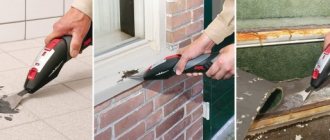
Using a core, you can make marks on any surface. It is advisable to use it when working with smooth materials. These are tiles, polished surfaces. Most often it is used when drilling metal. Therefore, core samples are often referred to as metalworking tools.
Masons also actively use it. Special mason cores have been created for this purpose. They are not much different from locksmiths. They are often powder coated in a bright color to make them easier to find if lost.
Tools for flat marking
Work must be performed on a flat and comfortable surface. Marking tables are used for this purpose:
- woody;
- iron.
Key conditions for the quality and design of tables:
Read also: What to do if my mother hits me
- Strength and durability. To ensure strength, the table legs are connected by horizontal bars. It is recommended to place large-scale marking plates on jacks.
- Sufficient surface area for work. Conventional tables have dimensions: length 2000–3000 mm; width 4000–5000 mm; height 700–1000 mm. The surface area of the table should be suitable for the dimensions of the sheets, tapes, and strips of material.
- Convenience. Tables are equipped with different devices:
- weights for fixing sheets of light material;
- prisms for installing pipes;
- clamps for securing metal sheets;
- rectangular and wedge-shaped gaskets for installing profiles and other parts.
The work site must be guaranteed with all the tools necessary for flat marking. The table provides a list of the necessary tools and certain tips for working with them.
| Tool | Function | Design requirements | Tips for use | ||
| Scriber | drawing marked lines on workpieces | · thin steel rod; · one end is sharpened at 45 degrees, the other is bent into a ring; · the sharp end is hardened | · to obtain thin marks, the tip must be hard and sharp; · during operation, the scriber is deviated from the ruler in the direction of its movement; it should be regularly pressed against the ruler with its tip | ||
| Outline | drawing contours parallel to the edges of the sheet | · material: copper or steel; presence of a graphite pencil in the working part | Reismus | · checking the location of workpieces; · carrying out parallel risks | · stand with scriber fixed at the required height; · fixation height is measured with a square |
| Kerner | · construction of centers of circles or holes; · drawing holes on the marking lines | · material - hard steel; · dimensions: diameter 8-13 mm, length 90-150 mm; · the end is sharpened at 60 degrees; · there are manual and automatic (set marks of the same size) | The automatic center punch does not require a hammer to operate | ||
| Locksmith's hammer | percussion tool for punching | use hammers weighing 50 - 200 g | the work is performed with light movements conveyed by bending the hand “from the shoulder” | ||
| Squares | · construction and control of angles; restoration of perpendiculars | preferred material - metal | · it is advisable to have squares with angles of 30, 45, 60 degrees; · a square with a shelf is used to check the correct placement of parts on the plate | ||
| Protractor with protractor | marking corners and checking mark alignment | preferred material - metal | The position can be fixed with a hinge screw | ||
| Compass | · construction of circles, arcs; Transfer of dimensions from ruler to workpieces | It is recommended to harden the legs of the compass | the tip of the compass is installed strictly in the punched hole | ||
| Marking plate | Serves as a working surface; · used for equipment storage | · located horizontally; · must be clean and dry | placed on cabinets, stands with drawers, tables | ||
| Templates, stencils | simplification and acceleration of marking of similar parts | durable steel templates | ensure a tight fit of the template to the workpiece | ||
| Vise | tool for securing small parts | ensuring smooth tightening efforts | For fine work, a small step is recommended; for coarse clamping, a wide step is recommended. |
Marking boards
Marking plates have a ribbed design, which gives them rigidity with a relatively low weight.
The working surfaces of marking plates must be precisely machined. To avoid deformation of the slabs during their operation, the castings are subjected to aging (exposure to air for a long time) between roughing and finishing processing.
On the upper surface of the marking plate (Fig. 1, a), in the absence of machine grooves, longitudinal and transverse grooves with a depth and width of 1-2 mm are cut so that the entire surface of the plate is divided into square sections.
What you need to know about the center punch
When choosing a core sample, you need to remember several important points about this type of instrument.
Firstly, it does not matter at all what cross-sectional shape the tool rod has.
It is much more important to pay attention to its other characteristics. Secondly, you should buy a device based on the diameter and type of drill with which it will be used
Secondly, you should buy a device based on the diameter and type of drill with which it will be used.
Thirdly, if you plan to use a center punch when working with soft metals, it is better to choose one with a smaller sharpening angle and vice versa.
Applying marks
The standard regulates the procedure for drawing marking lines:
- horizontal;
- vertical;
- inclined;
- curvilinear.
Applying curved elements after straight ones provides another opportunity to check their accuracy. The arcs must close the straight lines, the interface must be smooth.
Tools for marking
Direct marks are carried out with a well-sharpened scriber, without tearing off, in one step. At the same time, the scriber is tilted away from the ruler or square so as not to introduce distortions.
Parallel lines are drawn using a square and moving it along the reference ruler to the required distance.
If the workpiece already has holes, then a special tool, a center finder, is used to attach marking lines to them.
Center finder
In order to mark inclined lines, use a marking protractor with a hinged ruler fixed at its zero point.
Marking protractor
For particularly precise markings in plumbing, calipers are used. They allow you to measure distances and scratch marks with an accuracy of hundredths of a millimeter.
Marking of metal products and blanks: tools, methods, rules | Construction Bulletin
In the production of metal products, the source material - castings, sheet and profile products - does not correspond in size and shape to the designer's drawing. To cut off excess metal, drill, stamp, weld, or otherwise process a workpiece, key points of the drawing are applied to it. Applying to these points and lines, the processing is carried out.
Basic concept and types of markup
As a rule, unique parts and products produced in small and ultra-small series are marked. For large-scale and mass production, workpieces are not marked; instead, special equipment and control programs are used.
What is markup
The operation of applying the dimensions and shape of a product to workpieces is called marking. The purpose of the operation is to designate the places where the part should be processed and the boundaries of these actions: drilling points, bend lines, weld lines, markings, etc.
Marking is done with points, which are called cores, and lines, which are called risks.
Marks are scratched into the metal surface with a sharp tool or applied with a marker. Cores are filled with a special tool - a center punch.
According to the method of execution, there are such types of markup as:
- Manual. It is made by mechanics.
- Mechanized. Performed using mechanization and automation tools.
Based on the application surface, they are distinguished
- Superficial. It is applied to the surface of the workpiece in one plane and is not associated with the lines and marking points applied to other planes.
- Spatial. It is carried out in a unified three-dimensional coordinate system.
Notes on straightening and marking for thin sheet metal
The choice between surface and spatial markings is determined, first of all, by the complexity of the spatial configuration of the part.
Markup requirements
Plumbing markings must meet the following requirements:
- accurately convey the key dimensions of the drawing;
- be clearly visible;
- not to be abraded or lubricated during mechanical and heat treatment operations;
- do not degrade the appearance of the finished product.
Marking of parts must be carried out with high-quality inventory tools and devices that are subject to periodic verification.
Applying marks
The standard regulates the procedure for drawing marking lines:
- horizontal;
- vertical;
- inclined;
- curvilinear.
Applying curved elements after straight ones provides another opportunity to check their accuracy. The arcs must close the straight lines, the interface must be smooth.
Direct marks are carried out with a well-sharpened scriber, without tearing off, in one step. At the same time, the scriber is tilted away from the ruler or square so as not to introduce distortions.
Parallel lines are drawn using a square and moving it along the reference ruler to the required distance.
If the workpiece already has holes, then a special tool, a center finder, is used to attach marking lines to them.
In order to mark inclined lines, use a marking protractor with a hinged ruler fixed at its zero point.
For particularly precise markings in plumbing, calipers are used. They allow you to measure distances and scratch marks with an accuracy of hundredths of a millimeter.
Marking marking lines
In order to more accurately carry out the risk, cores are placed at its beginning and end. This allows you to visually control the position of the ruler while drawing.
On long-distance risks, auxiliary cores are also placed through
every 5-15 cm.
Circle lines are marked at four points - the ends of perpendicular diameters.
If already treated surfaces are marked, then punching is used only at the beginning and end of the marks.
After finishing, the marks are extended to the side surfaces and the cores are placed on them.
Marking techniques
The following techniques are used in plumbing:
- According to the template. Used in case of small-scale production. The template is made from rolled metal, the entire batch is marked (or even processed) through once marked slots and holes in this sheet. For parts with complex shapes, several templates can be made for different planes.
- Following the example. The dimensions are transferred from the part - the sample. It is used in the manufacture of a new part to replace a broken one.
- Local. Used in the production of complex multi-component products and structures. Blanks are placed on a plane or in space in the order in which they enter the final product and are marked together.
- Pencil (or marker). Used for workpieces made of aluminum alloys so that the scriber does not destroy the passivated protective layer.
- Accurate. It is done using the same methods, but special precision measuring and marking tools are used.
The selection of techniques is carried out in accordance with design and technological instructions.
Marriage during marking
First of all, when marking, defects that were made at previous stages of production emerge. Products from procurement sites or workshops, as well as materials purchased from other enterprises, reveal:
- violation of dimensions
- shape distortion
- warping.
Such castings or rentals are not subject to further marking operations, but are returned to the department or organization that caused the defect to correct it.
At the marking stage itself, defects can be caused by the following factors:
- Inaccurate drawing. The mechanic, without hesitation, displays incorrect dimensions on the part, and during further processing, defective products come out.
- Inaccuracy or malfunction of instruments. All marking tools are subject to mandatory periodic verification by the metrological service of the enterprise or an authorized metrological center.
- Incorrect use of tools or marking accessories. There are known cases when instead of calibrated measuring pads, ordinary pads were used to set the level. In this case, erroneous application of angles and slopes is also possible.
- Inaccurate placement of the workpiece on the marking table or plaza. They lead to distortions when setting aside dimensions, violation of parallelism and coaxiality.
- Wrong choice of reference planes. It is also possible that some of the dimensions were applied from the base planes, and some from the rough surfaces of the workpiece.
Separately among the reasons for defects are the marker's errors. These include:
- Incorrectly read drawing. It is possible to apply a radius instead of a diameter and vice versa, inaccurate application of the centers of holes relative to the center marks, etc. If any difficulties arise, the mechanic must seek clarification from the foreman or foreman.
- Carelessness and inattention when punching and drawing lines.
The human factor, unfortunately, is the most common cause of marking defects.
Negligence can be committed by both the mechanic himself and his supervisors, who did not check the tool on time or issued inappropriate marking devices.
Typically, marking operations are entrusted to the most experienced and responsible workers, counting on the fact that they will not mechanically transfer dimensions from the drawing to the workpiece, but will treat the matter thoughtfully and promptly notice and eliminate the reasons for possible defects on their own or by contacting their managers.
How to level walls using plaster and drywall. Why does the electrode stick when welding? A house with an area of 1 square meter. Our happy future?
What is a marking operation?
It should be immediately clear that marking does not necessarily mean fixing the distance from one point to another when constructing a particular structure. As production and construction standards become more complex, the manufacturability of marking processes also increases. During this action, a foreman at a construction site or an operator on a production line can determine the parameters of the workpiece, the characteristics of its location relative to other objects, etc. A modern marking tool allows you to record indicators such as length, width, height and angle. Some models such as squares are also focused on initially determining how well an object, its parameters or location meet the requirements. As for the marking process, it mainly involves manual handling of measuring and marking devices. The user, in turn, is required to be attentive, accurate and thorough in removing and recording data.
Marking. Marking a workpiece or part
Marking is the operation of applying lines (so-called marking marks) to the workpiece being processed or the part being repaired, defining the contours of the part or the area to be processed.
Marking of parts is used mainly in small-scale production of parts and when carrying out metalwork repair work.
To carry out various marking work, a mechanic must have special measuring and marking tools (rulers, thickness gauges, scribers, punches, etc.).
To install, align and secure the marked parts, use a set of special devices (linings, prisms, squares, etc.).
Marking is done on marking plates, on which all fixtures and tools are placed.
Marking boards
Marking plates have a ribbed design, which gives them rigidity with a relatively low weight.
The working surfaces of marking plates must be precisely machined. To avoid deformation of the slabs during their operation, the castings are subjected to aging (exposure to air for a long time) between roughing and finishing processing.
On the upper surface of the marking plate (Fig. 1, a), in the absence of machine grooves, longitudinal and transverse grooves with a depth and width of 1-2 mm are cut so that the entire surface of the plate is divided into square sections.
Large marking plates are installed on special stands (pedestals) with drawers for storing tools. Small marking plates are placed on wooden stands and installed directly on workbenches.
The height from the floor to the working surface of a marking slab of small or medium sizes is 800–900 mm, and of large slabs – 700 mm.
The marking plate must have free space to walk around and to be able to work from either side.
Checking the flatness of the marking plates is carried out using an accurate ruler and feeler gauge. To do this, the ruler is placed with its working surface on the working surface of the marking plate. The gaps between these surfaces are controlled with a feeler gauge. The thickness of the probe, which passes into the gap between the ruler and the marking plate, should not exceed 0.03–0.05 mm.
The correctness of the working surfaces of scraped marking plates (Fig. 1, b), intended for precise marking and verification work, is checked for paint using a straight edge. The number of spots in a 25x25 mm square must be at least 12.
Rice. 1. Marking boards
Equipment
In order to install the part on the working plane of the marking plate, support pads, prisms, jacks, special devices, cubes and squares are used, which have precisely machined prismatic and vertical surfaces perpendicular to the surface of the plate. Shims are also used to protect the working surface of the marking plate from damage by the untreated (black) surfaces of the parts being marked.
Flat (Fig. 2, a) and prismatic (Fig. 3) pads are placed directly on the working surface of the marking plate.
Rice. 2. Pads for installing the part on the marking plate
Rice. 3. Prism (a) and square (b) for installing parts
Parts that have a flat base, a flat end, or three supports spaced at a maximum distance along the dimensions of the part must be installed for marking on three pads selected in height.
If it is necessary to orient the part in a horizontal plane, then select pads or a set of pads for the supports, in which the part will take a horizontal position. In this case, it is also convenient to use height-adjustable pads. In Fig.
2, b shows an adjustable lining, which is adjusted in height by rotating screw 1, which moves wedge 2 along wedge 3. On the side surface of the lower wedge there is a scale that allows you to more accurately set the height of the lining.
Cylindrical parts are placed on prismatic supports with triangular cutouts (Fig. 3, a). A set of auxiliary tools usually contains several of these pads with the same cutouts.
For ease of marking, the part can be fixed to a square (Fig. 3, b) installed on the marking plate. The shelves of the square have through holes through which the part can be attached to the square.
THEORETICAL INFORMATION
METAL MARKING
Textbook Plumbing B.S. Pokrovsky, V.A. Horse pp. 51- 67
Purpose and types of markings
Metal marking is the operation of applying lines (scores) to the workpiece, which, according to the drawing, determine the contours of the part and the places to be processed.
Marking lines can be contour, control or auxiliary.
Contour marks determine the contour of the future part and show the boundaries of processing.
Control marks are carried out parallel to the contour lines “into the body” of the part. They serve to check the correct processing.
Auxiliary marks mark axes of symmetry, centers of radii of curvatures, etc.
Marking of workpieces creates conditions for removing metal allowance from workpieces to specified boundaries, obtaining a part of a certain shape, required dimensions and for maximum savings in materials.
Marking is divided into linear (one-dimensional), planar (two-dimensional) and spatial or volumetric (three-dimensional).
Linear marking is used when cutting shaped steel, preparing blanks for products made of wire, rod, strip steel, etc., that is, when the boundaries, for example, of cutting or bending, are indicated by only one dimension - length.
Planar marking is the application of various lines to the surfaces of flat workpieces on sheet and strip metal, as well as on the surfaces of cast and forged parts.
Planar marking is usually used when processing parts made of sheet metal. Planar marking also includes the marking of individual planes of parts of complex shapes, if the relative position of the marked planes is not taken into account.
When marking in space, marking lines are applied in several planes or on several surfaces.
Spatial marking is the most complex of all types of marking. Its peculiarity lies in the fact that not only individual surfaces of the workpiece are marked, located in different planes and at different angles to each other, but also the location of these surfaces is mutually linked to each other.
Various marking methods are used: according to a drawing, template, sample and in place. The choice of marking method is determined by the shape of the workpiece, the required accuracy and the number of products. When marking a part is repeated multiple times, a template is used. When using CNC machines, there is no need for marking.
When marking according to a drawing, axial lines are first drawn, then horizontal and vertical lines, and lastly, inclined lines, circles and arcs. After this, the contours of the part are marked.
In addition to the considered markings according to the drawing, markings according to the template are used.
The template is used when making parts or checking them after processing. Marking according to a template is carried out when producing large batches of identical parts. It is advisable because it allows you to avoid repeating labor-intensive and time-consuming markings according to the drawing if you do it once when making the template. All subsequent operations of marking blanks consist of copying the outlines of the template. In addition, templates can be used to control the part after processing the workpiece.
Templates are made from sheet material 1.5-3 mm thick.
Marking in place is carried out in cases where the parts are mating, and one of them is connected to the other in a certain position. In this case, one of the parts acts as a template.
The process of transferring the contour of a part, its bend lines, cutouts and other markings from the template to the metal is called basting.
Depending on the shape of the blanks and parts to be marked, marking can be planar and spatial (volumetric).
When marking spatially, it is very important to correctly maintain the relative position of the planes on which the marking is carried out.
When marking, allowances for subsequent processing and assembly are taken into account. If the parts are connected with an overlap, then the dimensions of the parts must be increased by the amount of this overlap. The allowance for processing edges after cutting them with scissors is 2 - 3 mm, and for gas cutting - 4 mm. Cylindrical and conical parts are marked taking into account the thickness of the metal. The marking should ensure cutting of metal with the least waste.
The accuracy of marking significantly affects the quality of processing. The degree of marking accuracy ranges from 0.25 – 0.5 mm.
Errors made during marking lead to defects.
Technical requirements
The technical requirements of marking include, first of all, the quality of its execution, on which the accuracy of the manufacture of parts largely depends.
The marking must meet the following basic requirements:
1) exactly correspond to the dimensions indicated in the drawing;
2) marking lines (marks) must be clearly visible and not erased during processing of the part;
3) do not spoil the appearance and quality of the part, i.e. the depth of the marks and core recesses must meet the technical requirements for the part.
Planar marking techniques
A prerequisite for the correct application of markings on flat surfaces is their high-quality preparation. Preparation procedure:
- Using steel brushes, remove dirt, scale, and traces of corrosion from the surface of the workpiece.
- Check the workpiece material for defects: cavities, cracks, blisters.
- If defects are identified, they should be measured and measures taken to remove them.
- If it is not possible to remove defects, then a marking plan should be drawn up so that they are removed from the surface during processing.
Before performing planar markings, it is recommended:
- Analyze the drawing of the part, its purpose, characteristics and dimensions.
- Develop a marking plan.
- Using reference books, determine processing allowances.
- Paint the surface.
The purpose of coloring is to ensure the clarity of the marks applied. When painting a small part, it is held at an angle in the left hand. Using a paint brush, apply paint thinly in cross movements. Large pieces are painted using a roller or spray.
Recommendations for staining are given in the table.
| Surface type | Coloring agents |
| any types of surfaces, except hot-rolled steel and non-ferrous metals | quick-drying water-based paints, alcohol varnishes |
| cast iron or steel workpieces | copper sulfate: · in pieces; solution (3 teaspoons per 200 g of water) |
| untreated black blanks | a solution of chalk in water (the consistency of thick milk) with the addition of drier or linseed oil |
The technique used for applying planar markings depends on its purpose, the material on which the lines are applied, and the shape of the parts being marked.
Marking work can be performed:
- according to the drawing - all elements of the part are transferred from the drawing to the material;
- according to a template - the contours of the part are outlined on the material along the contours of a pre-made pattern, template or stencil;
- according to a sample - used when there is no drawing and template, dimensions are taken from a sample of the part being replaced;
- in place - carried out during assembly or adjustment to the size of assembly units of dimensional parts.
If a drawing is used during work, the order of marking is as follows:
- Carefully study the drawing, find out the material of the part and the process of its manufacture.
- Establish methods and procedures for applying lines and cores to the material.
- The dimensions shown in the drawing should be marked using special marking tools and measuring instruments. It is not recommended to transfer dimensions from the drawing using compasses, even if the drawing is made on a scale of 1:1. This is due to the fact that the dimensions of the paper on which the drawing is applied may change as it dries.
- Set the base from which the marking will be carried out. The base can be:
- edges of the material to be marked;
- previously drawn lines, for example, axial, center.
- The order of drawing lines:
- in the horizontal direction;
- in the vertical direction;
- arcs, fillets, circles;
- slanted lines.
- Mark the lines.
- Check the presence of all lines from the drawing on the marked surface.
Techniques for high-quality marking:
- Marks on steel workpieces are made with a scriber. On sheets of aluminum-based alloys, all internal lines, to avoid damage to the coating, are drawn with a pencil, contour lines with a scriber. For cleanliness, the line is drawn only once. If the line is poorly drawn, then this area should be painted over, allowed to dry and the line drawn again.
- When working with a center punch, with your left hand, place it with its pointed end exactly in the required place, tilting it away from you and pressing it to the intended location. Afterwards, the punch should be quickly brought to a vertical position and lightly hit with a hammer. When applying the punch, the following nuances should be taken into account:
- the centers of the punches must be located clearly on the lines, so that after processing operations half of the hole remains on the workpieces;
- Be sure to mark the intersections of marks and roundings;
- on short marks, holes are made every 5-10 mm, and on long ones - 20-100 mm;
- the circle is marked at the intersection of the axes;
- on the treated surface, holes are placed at the ends of the marks;
- on cleanly processed surfaces, the lines are not marked; they are extended to the side edges, where the holes are placed.
- Perpendicular lines are drawn using a square. The workpiece is placed in the corner of the work table plate and secured with a weight. To mark the first line, the shelf of the square must be attached to the side surface of the slab. Then the square is moved to a perpendicular surface and a second line is drawn.
- When applying markings according to the template, you must use a properly sharpened scriber. It should be installed so that the generatrix of the cone moves smoothly along the contour lines of the template. The accuracy of the work is influenced by the conditions of contact of the template to the surface.
- When marking according to a sample, all dimensions are transferred from the used part to the workpiece. Before starting work, it is checked for sufficient allowances; the holes in the workpiece are closed with center plugs. The following is the sequence of actions:
- place the workpiece on the plate next to the part, taking into account the uniform distribution of allowances on the workpiece;
- gradually transfer all dimensions from the part to the workpiece;
- synchronously changing the positions of the workpiece and the part, transfer all dimensions with a thicknesser;
- using a square to check the compliance of the installation of the part and the workpiece along the lines drawn in the previous position;
- The marking should be completed by marking the marks.
Lesson summary: “marking blanks”
« MARKING BLANKETS
MADE OF THIN SHEET METAL AND WIRE »
6th grade-
01.02, 03.02, 28.01
Target:
introduce students to marking sheet metal blanks and
wires; instill skills in the rational use of materials;
promote the development of technical thinking.
Lesson type:
combined (mastering new knowledge, generalizing and systematizing what has been learned).
Teaching methods:
oral questioning, story, demonstration of visual aids,
practical work.
Lesson
progress
:
I. Organizational and preparatory part.
Greeting the teacher, checking attendance, checking students' readiness for the lesson, communicating the topic and goals of the lesson.
II .
Theoretical part.
1.
Repetition of the material covered.
Questions:
- What operation is called editing?
- Why is it necessary to straighten a workpiece made of thin sheet metal or wire before marking?
- What tools and devices are used when editing?
- How can you straighten thick wire?
- How to straighten thin and soft wire?
- How is thin sheet metal straightened?
- Why can only thin metal sheets be straightened with a wooden smoothing block?
- How do you control the quality of straightening sheet metal and wire?
2.
Presentation of new material.
The teacher accompanies his explanation by showing marking techniques.
Teacher's story plan:
- Marking the wire workpiece.
- Marking a workpiece made of thin sheet metal.
1.
Marking the wire workpiece.
In order to manufacture any product, you need to accurately establish the processing boundaries, apply the contours of the future product in the form of lines and points to the surface of the workpiece in compliance with the drawing dimensions. This plumbing operation is called marking.
Marking the wire (determining places of bending or cutting) is done using a ruler and pencil. If, for example, you need to bend the wire at a distance of 50 mm from its edge, then apply a ruler to the piece of wire so that the zero mark of the ruler coincides with the beginning of the piece of wire. Then a 50 mm mark is found on the ruler and a line is made opposite it on the wire. This will be the fold point.
When marking the places where the wire is bent for the manufacture of any product from it, it is taken into account that for each bend of the wire at a right angle, a piece of wire equal to slightly more than half its thickness is additionally consumed.
For example, if a piece of aluminum wire is 200 mm long and 3 mm thick
bend in the middle at a right angle, and then measure the wire to the bend and
after it and add up these dimensions, it turns out that the length of the piece of wire is like
decreased. It will be about 198 mm, that is, 2 mm shorter than before
flexion.
When making a round ring from wire, it is important to know how to determine
the length of the wire to make a ring of the given size. Size
wire ring is usually determined by the size of its diameter. Magnitude
diameter is 3.14 times less than the circumference. Therefore, to determine
length of wire to make a round wire ring, size needed
multiply the diameter of this ring by 3.14.
2.
Marking a workpiece made of thin sheet metal.
Marking of a workpiece made of thin sheet metal is carried out in order to determine
places for cutting or bending sheet metal and workpiece processing boundaries
in the manufacture of products.
Marking points -
cores -
are small depressions. Lines,
those applied during marking are called risks
. Risks are main and auxiliary. The main risks indicate the processing boundaries. From the auxiliary marks, the dimensions for making the main marks are set aside.
Marks and cores are applied to the workpiece using special marking tools: scribers, marking compasses, center punches, as well as measuring rulers, bench squares and marking hammers.
Scriber
is a sharpened steel rod and is used for
applying marks. Scribblers come in wire, turned, and bent
the end.
Marking compass
used for drawing lines of circles and arcs on the metal surface. Unlike a conventional compass, both legs
marking tools have pointed ends.
Using a center punch
When marking, small depressions, or cores, are obtained. These recesses are necessary to mark the centers of circles and arcs, as well as to more clearly indicate the marking marks, which may be erased during work.
When marking, metal measuring rulers are used to measure
workpiece dimensions and marking marks.
Squares
also serve for making marking marks.
The square allows you to make lines strictly at right angles. The control of already completed corners of the workpiece is also checked with a square.
Marking hammer
hit the punch striker when punching the centers of holes and marking marks.
Before marking, it is necessary to clean the workpiece from dust and dirt. The workpiece must be marked so that as little metal as possible goes to waste.
There are two types of marking: according to a template and according to a drawing (sketch).
Sample
- this is a device in the form of a plate with the outlines of a part that
is being manufactured. The template is applied to the sheet of metal from which the product is made.
It is rational to mark using a template in cases where you need to mark a large number of parts. Position the template so that it all fits on the sheet. To use material economically, they try to find such a position for the template on the sheet so that when subsequently cutting the workpiece from the sheet, there will be as little waste and trimmings as possible. The template is then pressed tightly onto the sheet. To do this, you can use a clamp, a fairly heavy object, or simply press it with your hand. Without moving the template, trace its contours with a scriber, pressing its tip tightly against the edge of the template. Then, using a punch and a marking hammer, small indentations (cores) are made along the marking marks. To punch the marks, the tip of the punch is placed exactly on the mark with a slight inclination away from you. Before striking the striker, the punch is moved to a vertical position.
Hammers for punching are used small ones, weighing 100-150 g. The distance between the cores can be 5-10 mm or more. This depends on the length of the mark: the longer the length, the greater the indicated distance can be.
Marking according to the drawing consists of transferring the points and lines of the drawing from paper to a sheet of metal. In order to carry it out, you need to know how parts and products made of thin sheet metal are graphically depicted.
If the part does not have bends in the sheet from which it is made, such as an eyelet, then the image is given in only one view - from the front. The thickness of the part is indicated by an inscription like “Thickness. 0.5" or using an extension line with a shelf, where an inscription like "S 0.5" is given.
Often a product made of thin sheet metal is made by bending its individual parts. This is, for example, a box for fasteners.
In this case, the workpiece is marked according to the development drawing of this product, showing the shape and dimensions of the part before the bending operation is performed.
The bend points are shown by a dash-dot line with two dots. The construction of a drawing of a development of a rectangular product should begin with an image of the base of the rectangle. After this, draw the other sides adjacent to the base along the fold lines. The development of a cylindrical product is a rectangle, one side of which is equal to the circumference of its base, and the other to the height of the product. When starting to mark, the sheet of metal is carefully inspected, checking for rust, irregularities and distortions. If necessary, it is cleaned and straightened. Determine the possibility of manufacturing parts of the required dimensions from the sheet. To do this, compare the largest (overall) dimensions of the part with the dimensions of the sheet. It is necessary that the dimensions of the sheet be slightly larger than the dimensions of the part. To make the marking lines more clearly visible, the metal surface is often coated with chalk paint or other solutions. Then the bases for marking are determined - lines or surfaces from which dimensions are set aside for applying other marking marks. In other words, the actual marking begins from the marking bases. Marking is usually done from the straightest edge of the sheet or from an auxiliary mark drawn in the middle of the workpiece.
When applying straight marks, the ruler or square is pressed tightly against the workpiece with the fingers of the left hand so that there is no gap. The scriber is taken with the right hand, like a pencil, and, without interrupting the movement, draws a line of the required length. When making marks, the scriber is pressed tightly against the ruler or square, deflecting it at a small angle.
The magnitude of this slope cannot be changed during the risk, otherwise the risk will turn out to be a curve. If the part has holes and radius curves, then first mark and mark the centers of these holes or curved arcs. Then, using a compass solution equal to the radius of the circle or rounding, curved contour marks are drawn. To do this, the tip of one (fixed) leg of the compass is placed in the punched center and, lightly pressing both legs of the compass to the surface of the workpiece, an arc of a given length is drawn with the other (movable) leg. In this case, the compass is slightly tilted in the direction of movement.
In factories, parts marking is carried out by marking mechanics. The templates are made by the most highly qualified mechanics - toolmakers.
Practical part.
Practical work
“Marking blanks made of thin sheet metal and
wire.”
1.
Organization of the workplace.
Students complete the task each at their own workplace. To complete the work you will need: a workbench, a vice, a steel plate, a plumber's hammer, a mallet, a wooden block, pliers, a board with nails driven in, a metal rod, planks, sheet metal blanks and wire.
2.
Introductory briefing. Task:
using the developed technological maps, make markings
product blanks made of thin sheet metal and wire;
Safety regulations.
It is necessary to comply with general labor safety rules, work only
proper tool.
The scriber and marking compass should only be kept on the workbench, not placed in
robe pockets.
After using the scribers, you should put them on their sharply sharpened ends.
safety plugs.
In order not to injure your hands, you need to hand the scriber to a friend with the handle facing away from you, and
put it on the workplace - with the handle facing you.
3.
Current briefing.
Students completing assignments independently. Current observations of the teacher, monitoring compliance with safety regulations, answering questions that arise during the work process, checking the correctness of assignments.
Possible mistakes:
discrepancy between the dimensions of the marked workpiece and the dimensions in the drawing or sample of the manufactured part;
Causes:
inaccuracy of the measuring instrument, non-compliance with marking techniques or inattentiveness of the worker;
inaccurate marking;
drawing marks several times in the same place.
4.
Final briefing.
Evaluation of student work results, selection of the best works; analysis of admitted
errors and analysis of the reasons that caused them; explanation of application possibilities
acquired knowledge, skills and abilities in socially useful work.
The final part.
1. Setting for the next lesson.
The next lesson will continue to introduce the technology of processing wire and thin sheet metal.
2. Homework
Read paragraph 23-24 of the textbook. Cleaning workplaces.
Marking techniques
The following techniques are used in plumbing:
- According to the template. Used in case of small-scale production. The template is made from rolled metal, the entire batch is marked (or even processed) through once marked slots and holes in this sheet. For parts with complex shapes, several templates can be made for different planes.
- Following the example. The dimensions are transferred from the part - the sample. It is used in the manufacture of a new part to replace a broken one.
- Local. Used in the production of complex multi-component products and structures. Blanks are placed on a plane or in space in the order in which they enter the final product and are marked together.
- Pencil (or marker). Used for workpieces made of aluminum alloys so that the scriber does not destroy the passivated protective layer.
- Accurate. It is done using the same methods, but special precision measuring and marking tools are used.
Techniques for marking metal parts
The selection of techniques is carried out in accordance with design and technological instructions.
Classification of marking tools
The entire series of marking tools can be divided into 3 categories:
- Measuring
- To maintain geometry
- To create lines
The categories of marking tools listed above are used in pairs. Typically, geometry measurement and control tools are combined. A striking example of a combined tool is a ruler. Such tools include a protractor.
Additionally, marking tools can be classified according to the material of the workpiece that is being marked. In this case, the tool can be divided into several categories:
- For marking metal
- For marking wood and other soft materials
Of course, there are tools for marking floors, walls, ceilings and other surfaces. But in these cases, standard markup tools will be ineffective. To create markings on large surfaces, laser levels and graphic plotters are usually used.
Now let’s learn more about the types of marking tools.
Tool for measuring and maintaining geometry
If increased demands are placed on marking accuracy, then the master cannot do without an accurate measuring tool. Such tools include:
- Ruler
- Roulette
- Calibrated bracket
- All kinds of templates
- Corner
- Center finder
The measuring tool makes it possible to accurately measure: the distance between points, the length of lines, center-to-center spaces, angles, etc.
- A ruler is a basic tool for measuring straight linear dimensions. The average ruler is about 30 (cm) long. But there are also longer models, up to 100 (cm).
Advanced rulers use both metric and inch scales. Metal rulers are usually used to mark workpieces. Although this tool can be plastic or even wooden.
of a folding meter has become widespread . This ruler consists of 10 segments of 10 (cm). The segments are connected to each other using hinges. This makes it possible to compactly store a fairly long meter meter.
- Tape measure - unlike a ruler, which has a very limited length, this tool is capable of measuring much larger linear dimensions.
The average household tape measure has a scale length of 3 (m). There are also longer tape measures, up to 10 (m) and even more.
The good thing about tape measure is that the marking scale is wound into a “roll”. Hence the name, “roulette”. Such a measuring instrument is easy to store, easy to move from place to place and convenient to transport over long distances.
an automatic tape winding mechanism in the device . But in long tape measures, the tape is usually wound manually, using a handle.
- Bracket - this measuring tool has a very narrow scope of application. Calibrated staples are used mainly in the mass production of certain parts.
Using a bracket, you can easily and quickly determine the distance between points. What other types of marking tools exist.
- A template is the same stencil with which you can transfer any graphic elements to the surface of workpieces, from single dots and lines to complex drawings, as well as numbers and letters.
Most often, templates are used in the serial production of parts.