Basic mechanisms of crank presses
TO
category:
Blacksmithing
Basic mechanisms of crank presses
Next: Screw Friction Presses
Crank presses are varied in design, but their main mechanisms and components—clutches, brakes, fuses, ejectors, etc.—have much in common.
Clutches If the flywheel and the entire transmission system were rigidly fixed to their shafts and did not allow the kinematic chain to break, then the crank machine would operate continuously as long as the electric motor was turned on. These were the first mechanical presses. The disadvantages of such a drive system are obvious. First of all, servicing the machine would be extremely difficult: a continuously moving slider would make it difficult to feed workpieces and remove finished products. Only fully automated devices could service such a machine. Stopping a press with a large flywheel would take considerable time, is inconvenient and dangerous.
These considerations dictate the need for a device that would connect the working shaft with the rest of the drive system only during the working stroke, and the rest of the time the flywheel could rotate freely on its shaft. Such a device is a clutch.
Modern crank presses use rigid clutches and friction clutches. A rigid clutch is characterized by the fact that the driving and driven parts of the coupling are connected by a rigid element. Rigid clutches ensure that the slider stops in only one specific position (usually the uppermost position). Friction clutches ensure engagement due to the friction that occurs between the pressing disks of the clutch, and allow you to stop the slider in any position, which is much more convenient for installing dies, adjusting them and setting them up. With a rigid clutch, this requires turning the flywheel manually.
Clutches must be reliable and completely eliminate the possibility of spontaneous activation, as well as ensure shock-free activation and disengagement of mechanisms on the move. For ease of maintenance, the coupling is located on the press so that access to it is simple and easy.
Of the rigid couplings in crank presses, only couplings with rotary keys are currently used.
Engagement couplings with rotary keys. When using couplings with rotary keys, a longitudinal semicircular groove is made at the end of the shaft (on which the flywheel rotates freely). The flywheel bushing also has one or more of these grooves. The lower part of the cylindrical key fits into the shaft groove. Its upper part is removed flush with the shaft, i.e., as if it serves as a continuation of its circumference. With this position of the key, the flywheel rotates freely relative to the shaft. A spring is constantly acting on the key, trying to rotate it in the shaft groove by 90°. This is prevented by a special latch; when the pedal is pressed, the latch moves away and the key rotates under the action of a spring. It slides into one of the grooves in the flywheel bushing and provides clutch.
When the power pedal is lowered, the latch returns to its original position, smoothly turns the key and turns off the press.
The design of the coupling with a rotary key is shown in Fig. 1. The crankshaft is connected to the gear through the engagement sleeve using rotary keys. The keys are installed in cylindrical sockets of the shaft. In the middle part, flats are made on the keys in such a way that their surface is a continuation of the shaft surface. Thanks to this, as long as the keys are not turned, the gear can freely rotate relative to the shaft.
Rice. 1. Clutch with a turning key: 1 - crankshaft, 2 - front ring, 3 - rear ring, 4 - spring, 5 - locking key, 6 - working key, 7 - gear wheel, 8 - engagement sleeve, 9 - working shank keys, 10 - pins, 11, 12 - synchronizing cams
The rear and front ends of the keys are cylindrical in shape and are located in the holes formed by the shaft sockets and the grooves of the rear and front rings, which are locked relative to the shaft. The switching sleeve is pressed into the gear and wedged relative to it with a key (the key is visible in section B-B). The inclusion sleeve has four cylindrical grooves, the diameter of which is equal to the diameter of the rotary keys. The length of the inclusion sleeve is 2-4 mm less than the length of the flats.
Under the action of springs attached to the pins and ends of the synchronizing cams, the rotary keys tend to rotate and take their working position, entering the grooves of the switching sleeve 8. However, this is prevented by the shank, which rests against a spring-loaded stop on the frame (not shown in the figure) and the keys.
If you remove this stop, then at the moment when, when the gear wheel with the engagement sleeve rotates relative to the shaft, the axes of the slots of the engagement sleeve coincide with the axes of the keys, they will rotate and connect the shaft and the wheel. The keys rotate at the same angle (usually 40-50°) thanks to synchronizing cams. But the key does not transmit torque, but only prevents the shaft from overtaking the wheel, which can happen in low-speed machines with large weight sliders. The key is a working one, it transmits torque and control is carried out through it.
The clutch disengages after the shaft has completed one (or several depending on the selected mode) full revolution. The clutch engages when the shank hits the stop. In this case, the inertia forces of the shaft overcome the force of the springs, the keys turn to the non-working position and the wheel is again able to rotate freely relative to the shaft, which is stopped by the brake in a given position.
Rotary keys must be made very carefully in order to accurately fit the shaft and bushing 8. If the accuracy is insufficient, the keys and shaft do not work correctly and quickly fail. Due to their larger clutch surfaces, keyed clutches operate smoother than rigid clutches. However, with such couplings, braking the shaft and slider is somewhat difficult. The brake can only work effectively after the key has come out of the groove, so the groove is made oversized.
Couplings with a rotary key are used on presses of small and medium forces.
Friction clutches are used in powerful crank presses. The desire to increase machine productivity leads to an increase in the number of strokes per minute. With increasing operating speeds, the operating conditions of the activation mechanism become more complicated, since it must ensure rapid movement of massive press parts without excessive shock. Sharp impacts negatively affect the operation of the machine, lead to rapid wear of contacting parts, and sometimes cause breakdowns. The smoothest (softest) engagement is provided by friction clutches.
Friction clutches connect drive elements due to frictional forces that arise between contacting parts - usually disks. In the first moments of switching on, some slipping of the clutch occurs, softening the shocks. However, slippage causes wear of the coupling and some energy loss due to heating of the rubbing parts. The disadvantage of friction clutches is that the force required to engage them is much greater than that of other types of clutches. Nevertheless, friction clutches are finding more and more widespread use, since these disadvantages are fully compensated by their main advantage - smooth operation.
Rice. 2. Clutch-flywheel of a horizontal forging press with a force of 12.5 MN (1250 tf): 1 - flywheel, 2 - drive disks. 3 - spring. 4 - studs. 5 - cover, 6 - piston. 7 — gear hub, 8 — drive disks, 9 — ring gear
Typically, couplings use several discs in contact with each other. The discs may be lubricated or immersed in an oil bath. In a dry clutch, friction discs with ferrodo linings are often installed between steel or cast iron discs. The specific pressure in this case does not exceed 200–350 kPa (2–3.5 kgf/cm2).
The friction of the discs causes the clutch to heat up. To improve heat transfer, parts in contact with rubbing surfaces are made massive. For the same purpose, the coupling casing is made with a large cooling surface, often providing special fins to improve heat transfer. Sometimes couplings are cooled by blowing air.
The amount of torque transmitted by the clutch depends on the force with which the discs are compressed. Usually this force must be quite large, so the discs are compressed by air pressure supplied to special pneumatic cylinders. If the air line accidentally breaks or the compressor electric motor stops, the pressure in the cylinders drops, the clutches turn off and the press stops.
By adjusting the air pressure, you can make the pneumatic friction clutch also serve as an overload protector. If the permissible force is exceeded, its disks will begin to slip and the engagement clutch will act as a friction safety clutch.
The friction disc clutch shown in Fig. 2, located directly in the flywheel. Its driving part consists of a flywheel, three driving disks, a cover and a piston. A gear ring is rigidly attached to the flywheel, the protrusions of which fit into the depressions on the outer surface of the drive disks, so the disks cannot rotate relative to the flywheel and at the same time have the ability to move somewhat in the axial direction. The leading part of the coupling is mounted on two double-row tapered roller bearings and can rotate freely on them.
The driven part consists of a gear hub and two driven discs. The teeth of the hub fit into the recesses of the driven discs, so the discs can only rotate with the hub, while at the same time
time the ability to move in the axial direction. On both sides of the driven disks, sheets of pressed cardboard impregnated with latex are reinforced with copper rivets with countersunk heads. This material has a high coefficient of friction.
The hub is rigidly connected to the drive shaft by two keys and can only rotate with it.
While the clutch is not engaged, springs 3 through pins 4 pull the middle and right drive disks to the extreme right position. In this case, a gap is formed between the driven and driving disks, and the flywheel rotates idle. To engage the clutch, compressed air is supplied to the space between cover 5 and piston 6. The piston, under air pressure, moves to the left, overcoming the resistance of springs 3 and compresses the drive and driven discs with great force. Significant friction forces arise between them and the rotation of the flywheel is transmitted to the hub and shaft.
To disengage the clutch, it is enough to release the pressure in the cylinder - the springs will immediately move the drive disks to the right.
A gap will form between the driven and driving disks, and the flywheel will again rotate idle.
In Fig. Figure 3 shows a single-disk clutch, in which the friction elements are made not in the form of solid linings, but in the form of inserts. The clutch is built into the flywheel, on which the support plate and splined cylinder are mounted. These slots guide the pressure plate connected to the diaphragm seal. The diaphragm cover is attached to the flywheel with studs.
The flywheel rotates freely relative to the shaft until the driven disk with friction inserts is clamped between the support disk and the pressure disk. This occurs when compressed air is supplied into the space between the diaphragm and the cover. The friction forces arising between disks 3 and 4 and the inserts transmit torque from the flywheel to the machine shaft. When air is released, the springs retract the disc and the clutch disengages.
The performance of such clutches is determined mainly by the design and quality of the friction inserts. The most widely used inserts are from getinax FK-16L and FK-24A. Recently, inserts made of more elastic material 8-45-62 have begun to be used.
The shape of the inserts is shown in Fig. 4. The most commonly used inserts are those shown in Fig. 4, a, however, inserts in Fig. 4, b are more technologically advanced.
Brakes. If you do not use special devices, then after the clutch is turned off, the working shaft will rotate for some time by inertia. A crank mechanism stopped in an arbitrary position can spontaneously move under the influence of weight; Both are inconvenient and dangerous for operating personnel, which is why all crank machines are equipped with braking devices.
Rice. 3. Single-disc friction clutch with inserts: 1 - flywheel. 2 - studs, 3 - support disk, 4 - pressure disk, 5 - diaphragm, 6 - driven disk, 7 - inserts, 8 - cover, 9 - cylinder. 10 springs
Rice. 4. Shapes of friction inserts: a - oval, b - cylindrical with a flat, c - segmented
Their purpose is to stop and hold the slider in its uppermost position after the engagement clutch is turned off. Braking is carried out due to the friction forces that arise between the brake drum and the band or shoe.
There are two types of brakes: continuous and intermittent. In continuous band brakes, the band and drum are in constant contact. The braking force is adjusted by tightening the spring; By changing it, you can ensure that the slider stops in the desired position.
Continuous action brakes are very simple in design and reliable, but they also have serious disadvantages. Due to the fact that they are constantly turned on, drive energy is constantly consumed to overcome friction forces, amounting to up to 30% of the total energy consumed by the machine. In addition, such brakes heat up very much and wear out quickly, so they are used only on small machines (force up to 1000 kN), for which simplicity of design and small dimensions are of paramount importance.
Intermittent brakes are activated only at the right moment. Their operation is synchronized with the operation of the engagement clutches in such a way that the brake is turned on after the clutch is turned off, and turned off a few moments before the clutch is turned on. Intermittent brakes are more practical and provide less energy consumption, since they are activated only after the end of the working stroke. Less heat is released in them and it has time to dissipate into the surrounding space, which protects the press from problems resulting from overheating of the shaft, bearings, etc.
Rice. 5. Periodic band brake: 1 - spring, 2 - brake band, 3 - roller, 4 - drum, 5 - shaft, 6 - cam, 7 - lever, 8 - adjusting nut
The intermittent brake is activated and deactivated by cams or pneumatic cylinders. The intermittent brake shown in Fig. 5, controlled by cam. It consists of a drum secured to the shaft with a key and a brake band with a ferrodo lining. A lever through a spring can tension the band, pressing it against the brake drum. By rotating the adjusting rack, you can change the spring tension, and therefore the force with which the belt is pressed against the drum. At the same time, the braking force will also change.
When the cam protrusion hits the roller, the lever rotates to the left, compresses the spring and tightens the brake band. At the same time, it is pressed against the drum and the brake is activated. When the lower part of the cam gets under the roller, the lever turns to the right, releases the spring and the brake is released. By turning the cam on the shaft, you can set the time for turning the brake on and off.
The brake shown in Fig. 6, is turned off not by a cam, but by a pneumatic cylinder, the piston of which is connected to a rod. While there is no pressure under the piston, the tension spring pulls the rod down, tensioning the tape and pressing it against the drum. The brake is on. When air is supplied under the piston, the air pressure overcomes the spring force. The piston rises up along with the rod, the belt moves away from the drum, and the brake is turned off. If there is an accidental drop in pressure in the network, the brake is activated, ensuring safe work on the press.
In Fig. Figure 7 shows the design of a very reliable disc brake. It is installed on the drive shaft. The brake housing is bolted to the frame. The pressure plate is bolted to the piston. To improve heat transfer, disk 8 is made hollow and equipped with internal ribs. The brake disc with getinax inserts is secured to the shaft with a taper key. The pressing force of the discs is created by brake springs and is adjusted using a disc that is bolted to the roof 6. The pneumatic cylinder is sealed by a membrane installed in the cover.
The cantilever arrangement of the brake makes it easy to adjust it, as well as replace the inserts as they wear out.
Circuit breakers. To protect the transmission mechanisms of crank presses from sudden overloads, which can be caused by low temperature of the workpiece, deviation of its dimensions from those specified by the technology and other reasons, safety devices are installed. They can limit the maximum force transmitted to the slider or the maximum torque in the drive elements. Safety devices must be very sensitive to overloads: they must open the machine drive at a strictly specified force or torque.
Rice. 6. Brake of a horizontal forging press with a force of 8 MN (800 tf): 1 - drum, 2 - belt, 3 - nut, 4 - rod. 5 - spring, 6 - cylinder, 7 - piston
The fuse is installed on the drive shaft or on the slide. In the first version, the press is protected from overloads caused by torque, and in the second, from overloads occurring on the slide.
Fuses can be single-acting (destroyed when the press is overloaded) and reusable (automatically restored after tripping).
The design of rupture fuses contains a rigid part that fails when overloaded. For further operation of the machine, this part must be replaced with a new one. Most often, fuses are made in the form of a breakable rod.
During normal operation of the press, the voltage in the fuse is close to its tensile strength, but does not exceed it. If the specified condition is met, a small overload (about 30%) is sufficient for the voltage in the fuse material to exceed the strength limit and it to collapse, while the loads in the working links of the machine will not exceed the permissible ones.
Rice. 7. Single disc brake with inserts: 1 - drive shaft, 2 - housing, 3 - insert, 4 - spring, 5 - bolts, 6 - cover, 7 brake disc, 8 - pressure disc, 9 piston, 10 - membrane, 11 — adjusting disk, 12 — bolts, 13 — bed
Rice. 9. Fuse with a breakable plate
During each stroke, the load on the safety rod increases sharply from zero to almost the limiting value, so they are made from materials with a high fatigue strength, close to the shear strength. However, the bearing capacity of the rod gradually decreases (the metal gets tired) and after about 5,000–15,000 strokes it drops by 30–40%. This must be kept in mind when operating crank presses.
During operation, when the crank machine is used at its maximum power, maintenance personnel, to prevent frequent replacement of a broken rod, sometimes increase its diameter and, consequently, strength. However, this is prohibited, as this may result in significant overloads of the machine, which can lead to serious accidents.
Fuses in the form of shear bars limit the maximum torque transmitted by the drive. To limit the force acting on the slide, fuses with a breaking plate are used. In this case, the working force is transmitted to the tool through the plate, which is destroyed when overloaded. The plates are usually made of steel 45, hardened to a hardness of HB 250-280. When replacing a broken plate with a new one, the heel is kept from falling out by a retainer.
Rice. 8. Fuse with a breaking rod: 1, 4 - gears, 2 - coupling half, 3 - rod
During prolonged operation, due to metal fatigue, the ultimate force will decrease slightly. If this is undesirable, replace the plate with a new one with the same dimensions. In no case should you increase the diameters d and D and the thickness h of the cut layer, as this can lead to overload and accident of the machine.
Destructible fuses also include hydropneumatic ones, which have a breaking plate in their system. This safety feature for multi-crank presses limits the load on each connecting rod.
Under the heel of each connecting rod in the slider there is a hydraulic cylinder, the thrust bearing serves as its piston. All cylinders are connected to the high pressure pump and to each other. The pressure from the pump is also transmitted to the plunger of the pneumatic cylinder. The pump is driven by an electric motor and provides pressure up to 20 MPa. The electric motor is turned on only during the working stroke of the slide. The total force of all thrust cylinders at this pressure is exactly equal to the nominal force of the press. A check valve is installed in the pump pipeline, which allows oil to flow in only one direction - from the pump to the cylinder.
The pneumatic cylinder has a piston connected to a plunger that is subject to pressure from a pump. The left cavity of the cylinder has atmospheric pressure. The cavity to the right of the piston is under a certain pressure of air entering the cylinder through a pipeline. The force from air pressure slightly exceeds the force from oil pressure on the plunger, so the piston under normal conditions occupies the extreme left position, pressing against the protrusion on the bottom of the pneumatic cylinder.
If the force on the slider (or at least on one of the connecting rods) reaches an unacceptable value, the oil pressure in the cylinders.
Rice. 10. Diagram of a hydropneumatic fuse for a multi-crank press: 1 - hydraulic cylinder, 2 - thrust bearing, 3 - connecting rod, 4 - electric motor, 5 - housing, 6 - pump. 7 check valve, c - plunger, 9 - pneumatic cylinder, 10 - piston, II - rod, 12 - contact, 13 - plate, 14 - safety casing
Pipelines are increasing. The check valve does not allow oil to flow to the pump. Due to the increase in pressure, the force acting on the plunger will exceed the force acting on the piston, and the piston will move to the extreme right position. In this case, the central rod of the piston will break through the cast iron plate, and compressed air from the right cavity of the cylinder will escape into the atmosphere (the safety casing has holes for air passage). At the same time, the rod will close an electrical contact, which gives the command to turn off the press clutch and turn on the brake.
High-pressure oil enters the left cylinder cavity through the hole in plunger 8, and the pressure in all thrust bearing hydraulic cylinders will decrease.
Before the fuse operates, the most loaded thrust bearing has time to make only a small move. It is so small (0.2 mm) that there is practically no misalignment of the slider.
In order to prepare the fuse for operation again, it is necessary to install a new plate, drain the oil from the left cavity of the cylinder and apply pressure to its right cavity. Despite some complexity, such fuses work quite reliably.
Recoverable fuses are divided into three types: friction, slipping when the machine is overloaded; hydraulic, in which, when overloaded, the liquid escapes through the valves; spring-lever ones, in which the links, when the press is overloaded, change their position, restoring it again during the second stroke.
The simplest safety friction clutch is shown in Fig. 11. It is located in the flywheel, which is not rigidly fixed to the shaft, but can rotate relative to it. The friction clutch disc is mounted on a key and is pressed to the flywheel with bolts through a ring. To increase the coefficient of friction, ferrodo pads are attached to the clutch disk on both sides.
In some cases, friction clutches use friction between parts that are in contact not along planes, but along a conical surface.
Rice. 11. Safety clutch: 1 - flywheel, 2 - shaft, 3 - clutch, 4 - lining, 5 - ring, 6 - bolt
The design of the hydropneumatic resettable fuse is shown in Fig. 12. An adjusting nut is screwed onto the connecting rod screw, resting its lower end on the cylinder piston. The cylinder is attached to the slider base plate. Oil is supplied to the cylinder by a pump from the reservoir. The hydraulic system has a shut-off valve whose plunger prevents oil from flowing from the cylinder into the reservoir. The shut-off valve is held in the closed position by air pressure acting on the piston. The air pressure in the receiver can be adjusted, thereby changing the value of the maximum force on the connecting rod.
When the actual force exceeds this value, the air pressure on the piston will no longer be able to hold the plunger in the uppermost position. The plunger will move down and begin to force oil from the cylinder into the reservoir. At the same time, the pin connected to the piston will close the limit switch and turn on the sound signal. After opening the shut-off valve, the screw together with the nut can travel a distance equal to the height of the hydraulic cushion, with the slider stationary. This prevents the press from breaking.
The pressure in the cylinder during the downward stroke of the piston and when the press stops is maintained at the level to which the receiver is configured. But when the slide moves upward after overload, the pressure in the hydraulic cushion will drop. As a result, the pressure switch will turn off the press drive and turn on the pump, which will pump oil from the reservoir into the cylinder until the pressure in the cylinder reaches a predetermined value. After this, the pressure switch will turn off the pump and give permission to turn on the press.
Rice. 12. Hydropneumatic fuse: 1 - screw, 2 - nut, 3 - piston, 4 - cylinder, 5 - slider, 6 - piston, 7 - plunger, 8 - limit switch, 9 - reservoir, 10 - pressure switch, 11 - pump , 12 — receiver
Rice. 13. Ejectors: a - for the upper stamp: 1 - shtnft, 2 - stop, 3 - movable cross member. b - for the lower stamp: 1 - pin. 2 - slider, 3 - upper die, 4 - forging, 5 - lower die, 6 - body, 7 - spring
Thus, after reloading, no parts need to be replaced and the press is automatically ready to continue working. This is a great advantage of hydropneumatic fuses over hydraulic fuses with a breaking plate.
Ejectors. Ejectors of various designs are used to remove finished products from dies. The ejector for the upper half of the die (upper die) is shown in Fig. 13, a. A movable cross member is inserted into the through slot of the slider. Its upward movement is limited by adjustable stops. A movable pin passes through the slide and the upper half of the die. If, after the end of the working stroke, the product remains in the upper half of the die, then when the slide moves upward, it will be pushed out by the pin. This will happen because the crossbar, having reached the stop, will stop, the pin will also stop, and the slider will continue to move upward. As a result, the pin will come out of the recess in the upper half of the die and push the forging out.
The ejector for the lower half of the stamp is shown in Fig. 13.6. While the dies are closed, the pins are pushed down and compress the springs. As the slider and the top half of the die (upper die) move upward, the springs tend to expand and push the pins upward. Resting against the forging, the pins push it out of the lower half of the die.
In some ejector designs, the pins are driven by pneumatic cylinders that are constantly under pressure.
Pillows. Currently, in order to expand technological capabilities, almost all presses with a force of over 1-1.6 MN are equipped with pillows that serve to push products out of the lower part of the die, press the flange of the drawn part and carry out other operations that do not require much effort.
The most widely used are simple air bags. The pillow shown in Fig. 14, a, is installed under the table on open-type presses with low force. Air is supplied to the cushion cylinder through the piston rod. The force created by the cushion is determined by the air pressure and the area of the piston. If the dimensions of the table do not allow placing a pillow with a piston of the required diameter, use pillows from several sections installed in series. In this case, the force acting on the pillow slider is the sum of the forces acting on the three pistons.
Rice. 14. Pneumatic cushions: a - single-piston, b - three-piston; 1 - slider, 2 - piston
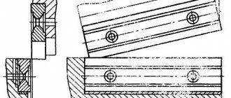
Rice. 15. Wedge mechanisms for regulating the size of the die space: a - using a table wedge, b - using a wedge above the upper hinge: 1 - wedge, 2 - wedge pad, 3, 4 - levers, 5 - liner, 6 - cheek, 7 - axis
To adjust the height of the cushion, a worm gear with an electric drive is used, located at the lower end of the rod.
To adjust the size of the die space, wedge mechanisms are usually used. In crank hot-stamping presses, the table wedges move for this purpose; in stamping crank-knee presses, the wedge cushion is shifted above the upper hinge.
Information about the manufacturer of the single crank press K2019
The K2019 press was produced by the Kursk Forging and Pressing Equipment Plant , founded in 1943.
Currently, the K2019 press is produced by:
- Dolina, PJSC Kuvandyk plant KPO, Kuvandyk, Orenburg region.
- PressMash, LLC Machine Tool Association, Moscow
Machine tools produced by the Kursk Forging and Press Equipment Plant
- K2019
open single-crank press for sheet stamping 80 kN - KD2114
single-crank open press for sheet metal stamping 25 kN - KD2118
single-crank open press for sheet metal stamping 63 kN - KD2318
single-crank open press for sheet metal stamping 63 kN
DIY electro-hydraulic press - Do it yourself
Equipment such as an electro-hydraulic press, due to its versatility and high efficiency, is actively used both in large manufacturing enterprises and in small workshops, as well as at car service stations. Using a hydraulic press equipped with an electric drive, you can solve many technical problems, which include:
- pressing, pressing out of gears, bearings and shafts;
- stamping, straightening and bending of metal products;
- pressing of products made from wood shavings, plastic and metal.
The electro-hydraulic press R-342M is intended for performing work on pressing, straightening and pressing in repair shops
A serial electro-hydraulic press will be quite expensive, but you don’t have to buy it, but make it yourself.
Installation of the hydraulic cylinder on the bed
The process of installing a hydraulic cylinder on the frame of a homemade hydraulic press is carried out in a certain sequence.
1. Adjustment of hydraulic cylinder, flange and plate
The body of the hydraulic cylinder, so that it can be placed in the inner part of the flange, is turned on a lathe.
The flange, which can be made from a car hub, is also processed on a lathe.
In order to make a hole in a metal plate that will be used as a base for installing a hydraulic cylinder, it is necessary to weld a round boss to it. With the help of the latter, such a plate will be fixed in the lathe chuck.
20 mm thick plate with a welded boss in the center
After the hole in the slab is bored out, it is welded to the beams of the base frame.
The flange, in which the mounting hole has already been prepared, is put on the hydraulic cylinder and welded in a circle.
Flange welded to hydraulic cylinder
It is very important that the flange and hydraulic cylinder are connected as smoothly as possible; for this, the adjacent surface of the flange must be machined on a lathe. 2. Installation of upper beams and hydraulic cylinder
The plate, which is already connected to the beams, is installed on the frame and connected to it by welding.
Through the holes on the mounting part of the flange, holes are drilled in the plate, which are necessary for placing the mounting bolts.
The installation of the upper beam is carried out strictly perpendicular to the supports
The hydraulic cylinder should not be attached to only one point, so it is necessary to make another flange, put it on the top of the cylinder and weld it to the beams.
Installing the Top Flange
T-beams installed in the upper part of the frame are connected to each other by welding.
3. Installation of the frame and oil station
In order for the hydraulic press you have made to fully function, you need to install an oil station on it and connect it with a hydraulic cylinder using hoses.
Installation of a frame and a two-flow hydraulic station delivering a pressure of 700 bar
Thus, it is not difficult to make a hydraulic press with an electric drive with your own hands. At the same time, you will have at your disposal equipment that can solve many technical problems.
Making a hydraulic press with your own hands
The hydraulic press has become widespread. This device is used in many auto repair shops for pressing and unpressing bearings, various gears and shafts. In a home workshop, a manual hydraulic press, made by hand, is very often used, since installations made in industrial conditions have a high cost.
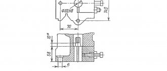
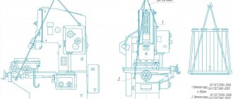
K2019 Dimensions of the crank press die plate
Dimensions of the crank press die plate K2019
Diagram of permissible forces of a single-crank press by 2019
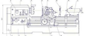
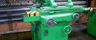
K2019 image of single crank press
Photo of single crank press k2019
Photo of single crank press k2019
Photo of single crank press k2019
Location of the main components of the K2019 single-crank press
Location of the main components of a single-crank press by 2019
- Bed K2019-11-001
- Drive K2019-21-001
- Eccentric shaft K2019-23-001
- Command apparatus - K2019-24-001
- Installation of clutch-brake K2019-26-001
- Slider K2019-31-001
- Air duct KE2118.01-41-001
- Drive guard K2019-71-001
- Command apparatus fencing - KE2114.01-72-001
- Work area fencing -
- Electrical equipment K2019-91-001
- Push-button control station KE2114.01-92-00
- Flywheel -
- Pneumatic blower
Design
Features of performing technological operations at high (up to 1000...1200
0
C) temperatures determined the following composition of components of such equipment:
- AC asynchronous electric motor (for CGPS with particularly high forces exceeding 31.5 MN, synchronous motors and even DC drives are used as a drive).
- Powerful V-belt drive.
- A receiving shaft rotating in plain bearings, on which a flywheel is mounted on one side, and on the other, an open reduction gear that transmits torque to the eccentric shaft.
- An eccentric shaft, on one end of which a band brake is mounted, and on the other, a friction multi-plate clutch.
- The activation system (clutch, brake), with which the flywheel braking unit is also structurally connected.
- Crank mechanism with additional upper slider guides. The movable half of the stamp is attached to the lower end of the slide.
- A wedge mechanism for adjusting the closed height of the press, which is installed on the press table.
- A rigid frame assembled from individual elements and fastened together with tie rods. They are hot tightened to create the required level of compressive stress.
- The press table to which the stationary part of the die is attached.
- Lubrication and control systems for hot stamping presses. The latter necessarily includes elements of control and diagnostic equipment.
KSHP
KGS can operate either autonomously or as part of specialized stamping lines.
The operating features of the CGShP, in comparison with conventional crank equipment, are considered to be:
- High speed to ensure minimum workpiece cooling/waste time;
- High drive power, which is associated with the need to ensure increased energy consumption during a fairly short technological cycle of hot stamping;
- The presence of upper and lower ejectors (in the slider and table, respectively), the use of which prevents hot workpieces from sticking in the die;
- Non-adjustable connecting rod, which makes it more rigid and durable;
- Increased number of clutch discs.
On modern CGSH designs, instead of the traditional crank-and-rod mechanism, a crank-wedge mechanism is installed, which is advantageously distinguished by increased stamping accuracy and less wear of contact surfaces.
Location of controls for single crank press K2019
Location of controls for single crank press K2019
- Pedal
- Input switch
- Operating mode switch
- Counter
- Light signaling
- Local lighting switch
- Button "Stop continuous strokes"
- "General stop" button
- Button "Start electric motor"
- Buttons "Slider stroke" (Two-handed activation)
Design and principle of operation
The hot stamping press is designed for processing workpieces at temperatures up to 1200°C. At the same time, there are some features in the design of the equipment:
- For medium and low rated power, asynchronous electric motors are installed. At high power, the manufacturer uses synchronous units that develop a force of up to 31.5 MN.
- The rotational motion is transmitted through wedge-shaped belts.
- The main shaft that receives the movement is installed in bearing supports. On one side there is a flywheel, and on the other end there is a speed conversion mechanism for the eccentric shaft.
- On the eccentric shaft, on one side, band brakes are installed, and on the other, a clutch for engagement, which contains several friction discs.
- A brake and clutch control system is mounted on the press.
- The machine is equipped with guides for the slider.
- The open height is adjusted by a wedge that is installed on the table.
- The bed consists of several elements that are connected by heated pins.
- The fixed part of the press is mounted on the work table.
- The lubrication and monitoring system for equipment operation is installed by the manufacturer.
Principle of operation:
- The electric motor transmits movement to the flywheel and intermediate shaft.
- The clutch is activated when the set number of revolutions per minute is reached, air is supplied to it under pressure and the eccentric shaft is connected to the connecting rod.
- The brake located at the end of the main shaft is automatically released.
- The slider begins forward movement with return.
- The moving part of the die, thanks to the slider, performs the hot pressing operation.
- When the slider moves upward, the finished product is automatically ejected.
Devices for securing the workpiece and automating the process can be additionally added to the design.
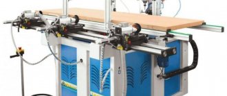
Industrial equipment (Photo: Instagram / kubanzheldormash)
This is interesting: Chemical metallization: technology, implementation at home
Kinematic diagram of single-crank press K2019
Kinematic diagram of the K2019 single-crank press
List of kinematic diagram elements
- Electric motor
- Drive pulley
- Drive flywheel
- Clutch-brake
- Eccentric shaft
- screw
- Eccentric bushing
- connecting rod
- Adjustment screw
- Crawler
- Ejector stop
- Ejector bar
- Air supply head
- Bearing
- Bearing
- Bearing
DIY hydraulic press with electric drive: components and assembly
Equipment such as an electro-hydraulic press, due to its versatility and high efficiency, is actively used both in large manufacturing enterprises and in small workshops, as well as at car service stations. Using a hydraulic press equipped with an electric drive, you can solve many technical problems, which include:
- pressing, pressing out of gears, bearings and shafts;
- stamping, straightening and bending of metal products;
- pressing of products made from wood shavings, plastic and metal.
The electro-hydraulic press R-342M is intended for performing work on pressing, straightening and pressing in repair shops
A serial electro-hydraulic press will be quite expensive, but you don’t have to buy it, but make it yourself.
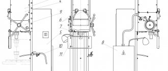
Description of the press K2019
bed
Press bed fig. 10 is cast iron, box-shaped, absorbs all the forces generated during stamping, and is mounted on two posts 8 and 10 using four pins.
In the upper part of the frame 2, in the cups 11 and 12, there are rolling bearings 13, which serve as support for the eccentric shaft.
On top, on the bevel of the frame 2, there is a plate for the sub-motor plate on which the electric motor is installed.
In front, on specially treated areas of the frame, prismatic adjustable guides 17 for the slide are attached.
The guides are adjusted with screws using threaded connections 14, 15 and 16.
The front part of the frame is closed by door 3.
A stamping plate 6 is fixed on the working plane of the table.
For work without failure, holes are provided on the table and plate.
An inclined slide 7 is attached to the lower part of the frame to remove stamped parts or waste.
Drive unit
Drive (see kinematic diagram in Fig. 9).
The slider stroke is adjusted by rotating the eccentric sleeve 2, which is connected to shaft 1 through a gear and is disengaged by rotating the nut 3.
After setting the required stroke value of the slider, the eccentric sleeve is brought into engagement with the eccentric shaft by rotating nut 3, which is locked with screw 6.
The required amount of slider stroke is set on scale 4 using pointer 5.
Installing the clutch-brake (Fig. 12)
The clutch-brake installation consists of a flywheel 1-3 and a clutch-brake 5-14, mounted on the eccentric shaft 4 of the press, an air supply head 15-18, mounted on the clutch-brake and a bracket 21, connected by pins 20 to the clutch-brake and mounted on press bed.
The flywheel 1 is supported by radial ball bearings 2, mounted on a sleeve 3, which in turn is mounted on an eccentric shaft 4.
The rigidly interlocked multi-disc friction clutch-brake with pneumatic activation consists of the following parts:
- driving - driving disks 5 of the clutch with friction linings;
- driven - hub 6 with a fixedly attached piston 7, cylinder 8 moving along the axis, intermediate disks 9, support nuts 10 installed along the threads of hub 6 and piston 7, pressure disk 11 mounted rigidly on cylinder 8;
- brake - brake disc 12 with friction linings.
As friction linings 5 and 12 wear, the gap “a” increases, which causes increased knocking when the clutch is engaged and air consumption increases. To adjust this gap, use split nuts 10, which are secured against unscrewing with nuts 13.
The unified air supply head consists of a housing 15, a fitting 16, rubber seals 17 located between them and radial ball bearings 18.
The clutch brake works as follows:
Compressed air through the air supply head 15-18, piston 7, hub 6 enters the pneumatic chamber “B” and moves the cylinder 8 along the axis of the eccentric shaft towards the clutch, which clamps the drive disks 5 of the clutch, which are constantly connected to the flywheel through fingers 19, ensuring the transmission of torque moment through the hub b onto the eccentric shaft 4.
At the moment of braking of the eccentric shaft 4, compressed air from the pneumatic chamber is released into the atmosphere through the air supply head 15-18, while the cylinder 8, under the influence of the springs 14, returns towards the brake and clamps the brake disc 18, sitting on the fingers 20, fixed in the bracket 21, which is rigidly associated with the bed.
Slider (Fig. 13)
The slider is the working part of the press to which the upper part of the die is attached.
The press slide 13 is box-shaped with prismatic double-sided guides. The slider is attached to the eccentric shaft by means of an adjusting screw 5 and a detachable connecting rod 4 in the housing and cover of which there are bronze sleeve bearings 2 and 3, covering the eccentric sleeve.
The total gap between the guides of the slider and the frame should be in the range of 0.04-0.08 mm. The gap in the ball joint should be no more than 0.015 mm. The gap between the bronze bushings of the connecting rod and the eccentric bushing is no more than 0.1 mm.
The ball head of the adjusting screw 5, the lower support 10 and the floating liner 8 are placed in the slider 12. After adjusting the gap in the ball joint, the nut 8, screwed into the slider 12, is locked with a screw 17.
The ball joint is supported by a shear safety washer 13, designed to withstand destruction when the press is overloaded. When cutting off the safety washer, use screw 17 to unlock nut 18, unscrew it 1.5-2 turns, lift the connecting rod with the adjusting screw, turning the press flywheel in the “Manual crank” mode, replace safety washer 13 by removing the cover on the window in the front of the slider , tighten nut 18 and lock it with screw 17.
The size of the die space is adjusted by rotating the adjusting screw by its hexagon; the set size of the die space is fixed by locking bushings 20, which are tightened by a screw with a lock nut 19.
The lower limit of die space adjustment is limited by clamp 23.
The amount of adjustment is determined by ruler 6.
At the bottom of the slide there is a hole for the shank of the upper die plate.
The shank is fastened with clamp 17 using two studs with nuts. Locking screw 15 serves for additional fixation of the stamp shank, as well as for repelling the clamp when removing the stamp.
In the groove of the slider there is an ejector rocker, spring-loaded with two clamps.
Command apparatus. (Fig. 14)
The command device is designed to switch current in the electrical control circuits of the press and control the operation of the pneumatic blower.
The command device is installed on the left end of the eccentric shaft. Aluminum disks 1, 2, 3 are fixed to the sleeve 4. Contactless switches 8, 9 and 10 type BVK 201-24 are installed on bracket 7, fixed to the frame.
- BVK (SQ1), switched by disk 2, controls the solenoid valve of the U7122A pneumatic distributor;
- BVK (SQ2), switched by disk 1, controls another electromagnetic valve of the dual three-line pneumatic distributor (stopping the TDC slide);
- BVK (SQ3) blocks the downward movement of the slider when turned on two-handed (when the slider does not reach BDC, releasing the two-handed turn-on buttons causes the slider to stop).
Description of the press
The operation of the press is described in words like this: The engine with the flywheel rotates constantly. When the pedal (or button) is pressed, a pneumatic clutch is activated, through which the rotation of the flywheel is transmitted through the crank to the press block. This block, with a punch or cutter installed on it, squeezes out the metal or cuts out the required parts.
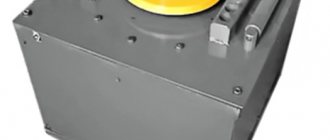
Flywheel:
Press flywheel. The hose in which the air operates the coupling is visible
Have you seen the operation of a steam locomotive, where the longitudinal movement back and forth is converted into rotational movement of the wheel? Now, the same thing happens in this press, only in reverse - the rotational movement is transformed into an up and down movement.
The position of the flywheel to stop it (that is, to turn off the clutch electromagnet) is determined using a non-contact sensor BVK201:
Non-contact sensor for determining the angular position of the press flywheel
Here is a picture explaining the operation of this sensor:
Position sensor operation
The starting position is shown. The sensor is active, i.e. its contacts are closed. When the activator rotates at the end of the cycle, it falls into the slot and is deactivated. Next, inertia is important, thanks to which the activator rotates a little more so that the sensor becomes active again. This inertia is adjusted by pressing the clutch.
I needed to implement this algorithm in a real circuit.
On my blog there are also descriptions of the operating principles and electrical circuits of other presses - hydraulic and pneumatic presses. I recommend.
Nameplate:
Nameplate press KD 2122K force 16 tons
Compressed air with a pressure of at least 6 kgf/cm2 is constantly supplied to the press to operate the clutch.
There are instructions and diagrams on the Internet for this and similar presses, the circuit is very complex, with transistors, with many functions and settings. As a rule, the scheme quickly breaks down, and craftsmen (like me) convert it to a simplified version. What is the article about?
The work of the press can be seen in the video at the end of the article.
Electrical equipment. General information
Electrical diagram of the single-crank press K2019
The electrical equipment used on the press has the following composition and characteristics:
- main drive electric motor - asynchronous three-phase alternating current with a supply voltage of 380 V;
- electro-pneumatic valves УV1, УV2 in the pneumatic distributor У7122А for 24 V DC;
- control cabinet.
The description of the operation of electrical equipment is indicated in the passport for the control cabinet.
Locks
The electrical circuits of the press and control cabinet provide the following interlocks:
- Zero blocking;
- blocking of pneumatic valves;
- blocking the doors of the frame;
- flywheel guard window blocking;
- air pressure switch;
- two-hand control;
- braking angle;
- control valves.
Supplying voltage to the press circuit does not cause spontaneous switching on of electrical devices. This is achieved by inserting the closing contact of the KM magnetic starter into the circuit of its own coil.
Locking pneumatic valves
When one of the pneumatic valves of the U7122A pneumatic distributor is blocked, the microswitch SQ11 or SQ12 is activated and turns off the electric motor and the press clutch.
Lock screen protector
When operating with a pedal, turning on the press clutch is possible only when the screen is closed (the limit switch is pressed in the “Single stroke” mode).
When working with buttons SB3 and SB4 in the “Continuous strokes” mode, the clutch can only be engaged when the screen is closed (the limit switch is pressed in the “Continuous strokes” mode).
Bed door lock
When the frame door is opened, the limit switch SQ15 is released and the electric motor and press clutch are switched off by the normally open contact.
Flywheel guard window lock
When the flywheel guard window is opened, the limit switch is released and the electric motor and press clutch are switched off using a normally open contact.
Air pressure switch blocking
When the air pressure in the system drops, the SP relay is activated and, with its normally open contact, turns off the drive motor and the press clutch, and the red warning light on the control cabinet lights up
Blocking control channels and command device failure
Each valve of the dual pneumatic distributor is controlled from an independent control element of the command apparatus via an independent circuit. If one of the control channels or command apparatus fails, one of the pneumatic valves of the U7122A pneumatic distributor does not operate. Microswitch SQ11 or SQ12 is activated and turns off the electric motor and the press clutch.
Electrical control circuit for the PVG-8-2-0 press - Physics
Equipment such as an electro-hydraulic press, due to its versatility and high efficiency, is actively used both in large manufacturing enterprises and in small workshops, as well as at car service stations. Using a hydraulic press equipped with an electric drive, you can solve many technical problems, which include:
- pressing, pressing out of gears, bearings and shafts;
- stamping, straightening and bending of metal products;
- pressing of products made from wood shavings, plastic and metal.
The electro-hydraulic press R-342M is intended for performing work on pressing, straightening and pressing in repair shops
A serial electro-hydraulic press will be quite expensive, but you don’t have to buy it, but make it yourself.
Principle of operation
Hydraulic presses equipped with an electric drive are capable of developing enormous forces, which is explained by the design features of such equipment. The principle by which the electro-hydraulic press works is as follows.
- An electrically powered motor drives a hydraulic pump.
- The hydraulic pump, in turn, maintains the pressure of the working fluid in the first chamber of the press.
- The piston of the first chamber transmits pressure to the second cylinder of the electro-hydraulic press, where it increases significantly.
- The pressure created in the second chamber of the hydraulic cylinder is transmitted directly to the working body of the electrohydraulic press.
Diagram of a frame-type hydraulic press (click to enlarge)
Thus, the amount of working pressure that will be imparted to the working body of an electro-hydraulic press depends on how different the areas of the pistons in its two cylinders are.
The operation of the press, the main working body of which is a hydraulic pump, is based on Pascal's law, which states that the force acting on any area is transmitted throughout the entire volume, and it has equal value in all directions.
Crank press diagram
Let's consider the crank press diagram shown in Figure 17, which provides four operating modes.
Electric motor M,
activated by contactor K, rotates constantly and, through a mechanical transmission, drives the driving part of the friction clutch, which is controlled by an electromagnet EM, acting on the pneumatic system switches.
The engine operates from a network with a voltage of 380 V, the coils of the contactor K and the electromagnet are powered from the secondary winding of the transformer Tr with a voltage of 127 V, the control circuit and local lighting lamp LO - 36 V, signal lamps 1LS, 2LS - 6 V.
By creating a galvanic isolation between the network and control circuits, the transformer eliminates the appearance of parasitic circuits in emergency modes, leading to spontaneous switching on of the press.
Using the PR switch, the operating diagram of which is shown in Figure 18, four operating modes are provided:
1) automatic operation on continuous strokes;
2) single moves with two-handed control;
3) single strokes controlled by an electric contact pedal;
4) adjustment or jog mode.
As can be seen from the diagram in Figure 18, in the adjustment mode, contact PR1 is closed and the EM electromagnet and, accordingly, the friction clutch are turned on when the KnPm button is pressed and the RE relay is turned on.
During automatic operation, when PR2 and PRZ are closed, the clutch is also engaged by pressing KnPm with the VZR contact closed, when the protective grill enclosing the working area is lowered.
In the single stroke mode, when PR2 and PR4 are closed, after switching on the contactor K, through PR4 and the opening contacts of the electric contact pedal VPE and the two-handed control buttons 1Kn and 2Kn, the coil of the blocking relay RB is energized, which, when turned on through the contacts KA2, powers itself.
Figure 17 — Diagram of a crank press
| Mode pins | Automatic operation | Single moves when controlled from | Setup mode | |
| buttons | pedals | |||
| PR1 | — | — | — | X |
| PR2 | X | X | X | — |
| PR3 | X | — | — | — |
| PR4 | — | X | X | — |
| PR5 | — | X | — | — |
| PR6 | — | — | X | — |
Figure 18 — Operation diagram of the PR switch
With two-handed control (PR5 is closed), pressing the 1Kn and 2Kn buttons through PR5 and the closed contact P5 energizes the RE relay coil, which turns on the electromagnet of the EM pneumatic switch. The friction clutch engages and the crank shaft begins to rotate.
At the bottom dead center, contact KA1 closes and, through the PRZ relay RE, powers itself up. The buttons can be released, because The slide rises and is safe for your hands. Near the top dead center, contacts KA1 and KA2 open and the slider stops.
If the buttons are kept pressed all the time, the NC contacts 1KN and 2KN will be open. Near the top dead center, the KA2 contacts open and the RE relay disappears, turning off the RE with its opening contacts and the slider stops.
To get a new press stroke, you need to release the buttons and then press them again. This prevents the slider from moving again (doubling strokes).
When controlled from an electric contact pedal, opening contacts PR5 and closing PR6 introduces RE coils and VPE pedal contacts into the circuit instead of 1Kn and 2Kn. The press is turned on and the slider moves downwards when the grid is lowered and the B3P contacts are closed. Otherwise, the operation of the circuit is similar to that in two-handed control mode.
Control questions:
1 Option
1. What are the requirements for the electric drive and electrical equipment of crank presses?
2. Describe the operation of the crank press circuit in single stroke mode when controlled by an electric contact pedal.
Option 2
1. What control devices are used in presses?
2. Give a general description of the crank press circuit?
Option 3
1. Under what conditions are electric drives with asynchronous motors used?
2. Describe the operation of the crank press circuit in continuous stroke mode.
4 Option
1. Under what conditions are electric drives with synchronous motors used?
2. Describe the operation of the crank press circuit in single stroke mode with two-handed control.
5 Option
1. What are the features of using SD to drive presses?
2. What operating modes of the press are provided by the control circuit?
6 Option
1. What measures ensure safe servicing of presses?
2. What do lamps 1LS and 2LS signal?
7 Option
1. What is the purpose and operating principle of a cam control device?
2. In what mode is it possible to turn on the friction clutch without turning on the electric motor?
8 Option
1. What do the load diagrams of the torque of AD and SD look like when they are used in press drives?
2. What is the purpose of the KA2 contacts in the crank press circuit?
Types and scope of application
Both home-made and mass-produced hydraulic presses are classified according to several parameters:
- sizes;
- maximum force produced;
- design features of the equipment (in particular, the height of the rod).
The most powerful are hydraulic presses related to floor-type equipment.
A hydraulic floor-type press, distinguished by significant dimensions, is capable of creating pressure at one point, the value of which can reach tens of megapascals.
The scope of use of equipment of this type, which can be equipped with additional devices, is quite wide. Floor hydraulic presses are necessary to solve such technical problems as:
- installation and removal of bushings, shafts, bearings;
- pipe bending;
- pressing of products made from various materials, including metal.
Some models of floor-type electro-hydraulic presses provide the ability to change the height of the work table.
Electro-hydraulic press 2135-1M, force 40 tons
Tabletop hydraulic presses, along with their small size, are characterized by less power. The pressure created by such equipment, installed on a desktop or workbench, rarely reaches 20 tons. The compactness of tabletop electro-hydraulic presses allows them to be used in small automobile and home workshops.
An important parameter of electrohydraulic presses, in addition to the force they are capable of creating, is the height of their rod. This parameter, in particular, determines what size parts the equipment can work with. If for tabletop presses this parameter can reach 100 mm, then for floor-standing models it reaches half a meter.
Due to their versatility, electrohydraulic presses are used in many fields of activity. Such areas of activity, in particular, are mechanical engineering, woodworking and food industries. However, most often such equipment can be found at vehicle repair stations.
Using it, you can successfully solve not only all of the above technical problems, but also straighten dents and other damage to the car body.
Unlike pneumatic equipment, the use of which requires a rather complex pneumatic system, a hydraulic press with an electric drive can simply be connected to an electrical power supply, and it will function normally.
Why is a press needed in a home workshop?
At home, a low-power hydraulic press can be an indispensable assistant during car repairs and other types of work. To press out a silent block or bearing and press a new one in its place, you do not need to turn to a car service for help and pay a lot of money.
Using a press, you can make straightening with your own hands, bend a metal blank, firmly glue two parts together under pressure, compress cans, plastic bottles, cardboard or paper, squeeze out moisture or oil. Purchasing a factory-made press will cost a considerable amount.
But you can make this tool yourself , spending only on the required materials. Moreover, it is possible to make a device that is adapted and adapted to specific needs, taking into account the necessary tasks.
Since a homemade hydraulic press will in any case need a certain place, if you don’t have a workshop, you can install it in the garage.
How to make your own hydraulic press with electric drive
Serial hydraulic presses with electric drive are quite expensive, so it makes sense to think about how to make an electro-hydraulic press with your own hands. To do this you will need the following tools and equipment:
- welding machine;
- lathe;
- drilling machine;
- Bulgarian;
- electric drill.
This press will be able to produce a maximum pressure of 35 tons
The supporting structure of the electro-hydraulic press, which is subjected to the main mechanical loads, is the frame, the strength of which should be given special attention. A T-beam made of metal of such thickness that it can withstand the loads created by a hydraulic press without bending is well suited for these purposes.
Press frame made of I-beam
Structurally, the frame of a homemade electro-hydraulic press is a U-shaped frame, welded from T-beams and installed on a base, for the manufacture of which thinner channels and angles can be used. In the middle part of such a frame (along its height), a working platform is welded into it, for the manufacture of which thick-walled channels are used.
Technical characteristics of the K2019 press
Technical characteristics of the single crank press K2019
Technical characteristics of the single crank press K2019