Information about the manufacturer of the 7M430 slotting machine
The developer and manufacturer of the 7M430 slotting machine is the Gomel Machine Tool Plant named after. S. M. Kirov StankoGomel , founded in 1885.
Machine tools produced by the Gomel Machine Tool Plant named after. S. M. Kirova, StankoGomel
- 7D36
- cross-planing machine with hydraulic drive, 450 x 710 - 7D37
- cross-planing machine with hydraulic drive, 560 x 1000 - 7D430
- slotting machine with hydraulic drive, Ø 630 - 7D450
- slotting machine with hydraulic drive, Ø 800 - 7M36, 7M37
- cross-planing machine with hydraulic drive, 450 x 710, 560 x 1000 - 7M430
- slotting machine with hydraulic drive, Ø 630 - 737
— cross-planing machine with hydraulic drive, 450 x 900 - 7307d, 7310d
- cross-planing machine with hydraulic drive, 450 x 710, 560 x 1000 - 7403, 7405
— slotting machine with hydraulic drive, Ø 630, Ø 800 - 7430
— slotting machine with hydraulic drive, Ø 650 - GD200
- small-sized slotting machine with a mechanical drive, Ø 500 - GD320
- slotting machine with hydraulic drive, Ø 770 - GD500
- slotting machine with hydraulic drive, Ø 940 - IR-500
- horizontal multi-purpose milling machine, 500 x 500 - FSS350MR
- vertical cantilever milling machine, 315 x 1250 - FSS450MR
- vertical cantilever milling machine, 400 x 1600
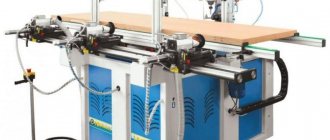
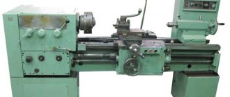
7M430 slotting machine with hydraulic drive. Purpose and scope
The hydroficated slotting machine model 7M430 is designed for the production of keyways, splines and grooves on shaped and flat surfaces, for slotting flat and shaped surfaces, cutouts, grooves in cylindrical and conical holes and slotting with undercuts up to 10°.
The machine is designed for processing external surfaces of products with a height of up to 320 mm and processing of internal surfaces of products with a height of up to 250 mm. The machine is suitable for use in individual and small-scale production, as well as in repair shops.
The presence of three types of table feeds (longitudinal, transverse and circular) makes it possible to process several surfaces on this machine from one installation. The presence of mechanical table feeds, an automatic stop mechanism, and remote control allows multi-machine service.
The machine is designed for processing by chiselling flat and shaped surfaces, grooves and grooves in a variety of parts, as well as various types of dies installed directly on the table or in fixtures. The ability to rotate the frame with the cutter allows you to process inclined planes without changing the position of the part.
Principle of operation and device selection
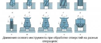
The main movement that the mechanism makes is reciprocal and forward. The device operates in vertical planes, but moves in a straight line, just like planing machines.
The most important element of the device is the slotting cutter, which is fixed in the slide. The table, with the workpiece fixed on its surface, carries out the feed.
IMPORTANT TO KNOW: Use of mini milling machines for metal
The reciprocal and translational actions of the machine occur periodically, while the slotting cutter can move in both linear and circular movements.
Both homemade and professional machines have two chiselling modes: simple and complex. A simple type of chiselling is done point-blank, and the cutter runs over some space and creates a series of holes of the same size and shape.
The second mode of operation of the device includes impact passing at an angle with inclined surfaces - a homemade machine may not be able to cope with this and a hydraulic one will be needed.
This device is needed to process hard-to-reach surfaces of parts. These include surfaces located inside the part used in different types of production, or partially hidden.
Most often, the machine is used to work with blind grooves and grooves of various shapes.
A homemade device is suitable for private workshops or small-scale production, but in large-scale industry they use complicated processing methods and therefore use a special device for working with CNC metal.
In private production, a workshop or a service center, the machine is most often used to work with metals (non-ferrous and ferrous), cast iron and other metal alloys.
The most used and popular type of machine is the “GD” model. You can find series 200, 500, etc. - they all belong to this type of device and meet its characteristics.
Video:
A more advanced model of the slotting machine: “S315TGI”, it is characterized by greater functionality compared to the previous one or home-made device models.
This machine can work with shaped, flat, conical and cylindrical surfaces. It also allows you to make splines, make recesses, grooves, grooves and holes.
The model supports several channel profiles, which are built individually based on the type of device setup you choose.
If you want to make a homemade machine, then you will need a diagram and instructions, but without the appropriate knowledge and skills, it will not be easy to assemble it yourself, so the easiest way is to purchase a ready-made machine.
When purchasing, you need to take into account several factors so that the device serves you for a long time and does not require repairs soon. First of all, you need to know the permitted height of parts for the device.
IMPORTANT TO KNOW: Design of a machine for bending reinforcement
This figure may vary and depends on what type of surface (internal or external) needs to be processed.
You also need to look at the declared power of the machine, the size of the cutter and the possibilities of its adjustment, find out whether the device has a transverse and longitudinal stroke, and what the permissible angle of inclination is.
Video:
The quality of operation of the device is also affected by the speed at which the working tool moves. To make the machine stable, buy products with a massive stand - then it will be easier to work with.
You need to be careful when choosing the size of the table itself, because... The ease of working with the device also depends on it.
In addition to the main parts, you need to find out if there is any additional equipment that is included in the device set.
The weight and size of the table are important not only as a factor in the convenience of working with the machine, but also for its placement in a workshop or other selected room - the device must be freely accessible, so do not choose too large models for small rooms.
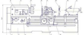
Brief description of the design of the 7M430 machine
The table moves both manually and mechanically. The circular feed of the table makes it possible to process round parts and gears on the machine.
The machine has hydraulic movement of the cutter and hydraulic feed of the table for each of its double strokes. The kinematic diagram of the machine ensures rapid movement of the table in the longitudinal, transverse and circular directions from a separate electric motor. The table can also be moved manually in the indicated directions. The machine table has a dividing mechanism that allows you to accurately divide the workpiece into the required number of parts.
The speed of movement of the cutter along the entire stroke length is constant. The machine has step-throttle regulation of the speed of the cutter and the movement of the table. Changing the direction of movement of the cutter occurs by switching the control spool using two stops located on the control panel cover. The same stops regulate the length and location of the cutter stroke.
There are two handles on the right side of the machine. One of them serves to switch the speeds of movement of the cutter, there are 4 such speeds in the machine. The other handle smoothly regulates the speed within each step.
The machine has a mechanism that allows you to process the product for a set processing length and automatically turns off the machine at the end of processing; The cutter stops in the upper position. The design of the machine ensures automatic retraction of the cutter from the product during reverse stroke. The machine has a remote control carried out from a pendant push-button station. From the push-button station, the main engine is started and stopped, as well as the cutter is started, stopped and adjusted. The machine has an idle speed limiter - when the cutter stops, the main engine stops. The machine is equipped with a tool cooling system. The lubrication of the cutter guides is forced from a separate reservoir using a plunger pump and manually from a manual lubricator.
Lubrication of the table - from 2 manual lubricators.
Setting up, adjustment and operating mode of the 7M430 slotting machine
Selecting cutting mode
To select a processing mode for a particular metal on a machine, it is recommended to use reference books on cutting modes.
Installation and adjustment of the cutter stroke
The size of the cutter stroke is adjusted using stops. For a given machining length, the stops must be installed so that the difference on the scale between one stop and the other determines the total machining length, taking into account the overruns of the cutter for each length.
The spread of the stops ensures processing of parts over the entire height.
The cutter is brought to the workpiece using the “Start the cutter” button, operating in jog mode, while the “Work - adjustment” cycle switch must be in the “Adjustment” position.
Table Feed Setting
Setting the selected table feed is carried out by turning the handwheel until the required number corresponding to the desired feed is set against the indicator line.
Machine adjustment
During the operation of the machine, the need arises to regulate individual components and elements in order to restore their normal operation.
Below are the units and methods of adjustment that require adjustment:
- Adjusting the wedge of the cutter
- Adjusting the wedges of the longitudinal and transverse table slides
- Adjustment of the tilting of the cutting head is carried out by the nut of the brake device, as well as by nuts that directly establish an adjustable gap between the folding board and the cutter;
- After some time, it may be necessary to adjust the rolling bearings, which requires slightly tightening the round nuts or flanges that create tension in these bearings;
- The safety ball clutch is adjusted using a nut and a locknut.
- Adjustment of hydraulic drive mechanisms was discussed in the section “Hydraulic drive of the machine”
- The feed box brake, which serves to prevent the shaft from rotating in the opposite direction, is adjusted with three nuts.
Roughness of the processed surface is not less than V 6
Machine accuracy class N
Technical characteristics of the hydraulically driven slotting machine 7m430
Manufacturer Gomel Machine Tool Plant, StankoGomel.
Basic parameters of the machine in accordance with GOST 1141-74.
- The stroke of the cutter is 120..320 , mm
- Distance from the table plane to the cutter guides, mm - 500 mm
- The distance from the table plane to the bottom edge of the cutter head is 10..580 mm
- Table diameter - Ø 630 mm
- Distance from the cutter to the frame (reach) - 590 mm
- The largest longitudinal table movements are 650 mm
- The largest transverse table movements are 500 mm
- The largest movements of the table are circular - 360°
- The largest dimensions of the cutter holder are 30 x 20 mm
- Electric motor power - 7 kW
- Full machine weight - 5.2 t
Installation procedure for the 7A420 slotting machine
Unboxing
When unpacking the 7A420 machine, first remove the top shield of the packing box, and then the side shields. Care must be taken not to damage the machine with the packing tool.
Transportation
To transport the unpacked machine, 2 steel rods are used. To protect protruding parts and the paint of the machine from damage by the rope, it is necessary to install wooden or felt pads under the rope.
Installation procedure for the 7A420 slotting machine
- Before installation, the 7A420 slotting machine must be thoroughly cleaned of the anti-corrosion coatings applied to the open and covered machine surfaces and coated with a thin layer of I-20A oil.
- First clean the grease with a wooden spatula, and then remove the remaining grease from the outer surfaces with wipes soaked in an organic solvent.
- The machine is installed on a concrete foundation, the depth of which is taken depending on the soil, but not less than 500mm.
- It is prohibited to install a slotting machine on the interfloor floors of buildings.
- The accuracy of the 7A420 machine depends on its correct installation on the foundation. The machine is installed on the foundation and aligned in the longitudinal and transverse directions using a level.
- When aligning the machine, it is necessary to place 4 wedges with an inclination angle of 50 under the base, by moving which the required accuracy of installation of the machine on the foundation is achieved.
- The deviation of the table plane from the horizontal position should not exceed 0.04 mm per 1000 mm of length in both directions. The finally adjusted machine is filled with cement mortar and after the mortar has hardened, the foundation bolts are tightened.
Preparing the 7A420 slotting machine for initial start-up and initial start-up
- Ground the 7A420 dovetailing machine by connecting to the general workshop grounding system.
- Connect the machine to the electrical network, checking the consistency of the network voltage and the electrical equipment of the machine.
- After familiarizing yourself with the purpose of the control handles, you should check by hand the operation of all machine mechanisms. Follow the instructions given in the sections “Electrical equipment” and “Lubrication system” related to starting the machine.
- Test the electric motor without turning on the working parts of the machine after connecting it to the electrical network, paying special attention to the operation of the lubrication system.
- After making sure that all mechanisms are working properly, you can begin setting up the machine for work.
ATTENTION! IF THERE IS NO OIL IN THE OIL INDICATORS, WORK ON THE MACHINE IS STRICTLY PROHIBITED!
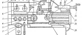
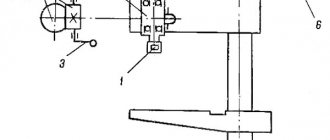
7M430 Arrangement of the components of the slotting machine
Location of the components of the 7m430 slotting machine
Location of the components of the 7m430 slotting machine
Specification of components of the 7M430 slotting machine
- 01. Bed _M30-01.001
- 02. Dolbyak with cylinder _M30-02.001
- 03. Feed box _M30-03.001
- 04. Table _M30-04.001
- 05. Cooling _M30-05.001
- 06. Electrical equipment _M30 06.001
- 07. Control _M30-07.001
- 08. Pipeline _M30-08.001
- 09. Accessories _M30-09.001
7M430 Location of slotting machine controls
Location of controls for slotting machine 7m430
List of controls for the 7M430 slotting machine
- Feed rate setting handwheel
- Mechanism for adjusting table movement to a given processing amount
- Handwheel for manual longitudinal movement of the table
- Mechanical longitudinal feed switch handle
- Reverse handle
- Mechanical circular feed activation handle
- Mechanical cross feed switch handle
- Switch "Lighting"
- "Start" button for quickly moving the table
- Button “Start” of the cutter (duplicated with handle 18)
- Main engine start button
- Cycle switch “Work - Setup”
- Nuts for fixing the rotation of the cutter slide
- Square for turning the cutter sled at an angle
- Hanging "Stop" button of the main engine
- Stops for setting the stroke length of the cutter
- Handle for manual movement of the cutter stroke
- Handle for starting and stopping the cutter
- Handle for steplessly changing the speed of the cutter between stages
- Handle for step change of cutter speed
- Signal light for connecting the machine to the network
- Batch switch for electric pump
- Batch network switch
- Cross slide clamp handle
- Longitudinal slide clamp handle
- Square for manual longitudinal movement of the table
- Square for manual lateral movement of the table
- Dividing mechanism handle
- Round table fixing nuts
7M430 Kinematic diagram of a slotting machine
Kinematic diagram of the 7m430 slotting machine
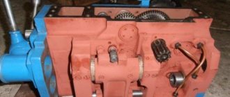
7M430 Description of slotting machine components
The machine bed consists of 2 parts: lower and upper, fastened together with screws, studs and pins. Both parts of the bed are box-shaped and have stiffening ribs, which ensures sufficient rigidity of the machine. At the bottom of the upper frame there is a reservoir for hydraulic drive oil with a capacity of 250 liters. There, a flange is attached to the left wall, in which a coupling is placed that connects the hydraulic pumps to the flange electric motor (the hydraulic pumps are placed inside the chamber and are screwed to the flange). The middle chamber of the lower frame is the reservoir of the cooling system. A plate with a hydraulic panel is attached to the right wall of the upper frame. There is a window in the left side wall for mounting a hydraulic drive. In the rear wall of the upper frame there is a niche in which the electrical cabinet is placed. The electrical cabinet doors have sponge rubber seals and a locking device that ensures the cabinet's tightness.
Dolbyak with a cylinder . The cutter is a cast iron hollow casting with rectangular guides; inside the cutter has stiffening ribs. A cutting head with tool holders is mounted in the lower part of the cutter. This unit contains a mechanism for mechanical retraction of the cutter during the reverse stroke of the cutter.
The folding board of the cutting head is connected through a bracket, a needle bearing, an eccentric and a gear shaft to a gear rack, which is placed in the groove of the cutter.
The toothed rack, moving together with the cutter, rotates the brake gear located in the slide of the cutter.
The throwing of the folding board occurs due to the rotation of the eccentric, motionless sitting on the gear roller.
The brake device is adjusted by a spring using a nut.
The hydraulic cylinder is a steel pipe mounted on a cutter slide.
The length of the cylinder is chosen in such a way as to serve the entire distance from the table plane to the guide slide with the cutter.
A piston with a rod moves inside the cylinder, the end of which is connected to the cutter. The cylinder is attached to the cutter slide motionlessly, and the piston with the rod and the cutter receive reciprocating motion. By supplying oil to the upper cavity of the cylinder, i.e., to the rodless cavity, we obtain the working stroke of the cutter, and by supplying oil to the lower cavity of the cylinder, i.e., to the rod cavity, we obtain the idle stroke of the cutter. Forced and manual lubrication systems for the cutter guides are installed in the cutter slide.
The feed box is designed to carry out transverse, longitudinal and circular working feeds of the table for each double stroke of the cutter and to quickly move the table in these directions.
Working feeds of the table are carried out as follows: When the cutter is switched to the working stroke, oil from the pump through the feed spool enters the feed box cylinder (see hydraulic and kinematic diagrams of the machine) and moves the piston to the right. The rack connected to the rod rotates a gear wheel z = 24, from which the shaft, connected through a safety clutch to the table assembly, rotates through a ratchet mechanism. Rapid movement of the table in all three directions is carried out by a separate 1.7 kW electric motor. The feed rate is adjusted by changing the piston stroke using a flywheel, a pair of gears, a nut and a screw. On the outside of the nut there is a cut rack, which engages with a gear sitting on the shaft of the G77-11 hydraulic feed throttle. Thus, at the same time, when adjusting the feed amount by changing the stroke of the feed piston, the amount of oil coming out of the rod cavity of the feed cylinder is throttled accordingly (see hydraulic diagram), which ensures feed stability at any speed. The set feed value is counted using a dial mounted on the handwheel. A brake is installed on the output shaft of the box, which counteracts the rotation of the shaft in the opposite direction.
A special mechanism for adjusting the table to a given length of processing the product with an automatic stop at the end of processing is built into the top cover of the feed box. The mechanism consists of a dial with divisions, a pointer, a pointer drive and an electric microswitch. The arrow is connected to the table assembly by a rigid kinematic chain. As it rotates, it presses a microswitch that stops the main motor of the machine. When setting the table stroke length, the arrow is secured in the specified position by tightening the nut.
The machine table mainly consists of a longitudinal slide running on the bed, a cross slide running on the longitudinal slide, a rotary table mounted on the cross slide and a gearbox.
Inside the rotary table of the slide there are channels through which the emulsion flows into the lower frame.
A gearbox is mounted at the right end of the longitudinal slide, transmitting movement from the feed box (unit 03) to the splined shaft of the circular feed worm and the screws of the longitudinal and transverse feed of the table. There are two squares on the gearbox cover, which terminate the transverse movement screw and the longitudinal feed shaft.
A dividing mechanism is mounted in the gearbox, allowing the workpiece to be divided into the required number of parts; The mechanism is connected to the rotary table through a spline shaft and a worm pair.
The rotary table is centered on the cross slide using a cone; it has three T-slots that allow workpieces to be secured. There is a centering hole with a diameter of 32 mm in the center of the turntable.
The rotary table is on a transverse slide, the transverse is on the longitudinal, and the longitudinal slide is fixed on the frame using clamps.
Between the transverse and longitudinal slides, as well as between the longitudinal slide and the bed, there are wedges to regulate the gaps that arise during operation of the machine.
The slide guides are rectangular.
All rotating shafts and worm are mounted in roller and ball bearings.
The design of the table ensures separate activation of each of the feeds: longitudinal, transverse and circular (it is possible to switch on two feeds simultaneously).
Cooling system . The cooling system is driven by an electric pump with a capacity of 22 liters per minute.
The electric pump is attached to the tank, which, in turn, is attached to the lower frame. The tank, together with the middle chamber of the lower frame, forms a reservoir for coolant. Tank capacity 55 liters. The table turntable (unit 04) has an annular chute at the edges, into which coolant is drained from the workpieces.
This chute is connected through a system of holes and channels to the middle chamber of the lower frame (reservoir). The tank has a hole at the bottom for draining the coolant, which is closed with a plug.
The cutter control unit provides:
- setting the location and stroke size of the cutter;
- manual reversal of the cutter when necessary;
- manual stop and cutter stop;
- setting the speed of the cutter.
1. Setting the position and stroke of the cutter is carried out using the power of two stops located on the right wall of the machine.
The stops move the hydraulic panel control spool through a special lever, thereby reversing the cutter.
The angle between the stops determines the stroke of the cutter. The relative position of the stops determines the position of the cutter stroke within the specified chiselling value.
The angle between the stops and their relative location are set along the limb.
The stops are driven from the cutter through a pinion-rack transmission and two pairs of bevel gears.
2. The reverse lever with rollers, which are acted upon by stops, has a handle for manual control.
3. The sector connected to the gear of the “start”-“stop” valve of the hydraulic panel sits on the roller.
At the end of this roller there is a hub with a handle, through which you can manually start and stop the cutter.
4. In addition to the handle for starting and stopping the cutter, two more hydraulic panel handles are located on the right wall of the machine. One of them serves to switch the speeds (steps) of movement of the cutter; there are four such steps in the machine; the other is for smooth speed control within each step.
The lubrication of the parts of this unit is forced from the hydraulic drive system of the machine.
The pipeline connects the working cylinder, feed box cylinder, hydraulic panel, pumps and auxiliary equipment.
The hydraulic panel is attached through an intermediate plate to the cast frame of the control unit. Together with the frame and the intermediate plate, the hydraulic panel is attached to the right wall of the frame, which has a window for removing the hydraulic panel. Installation of the hydraulic panel with an intermediate plate and frame is carried out through a window in the left wall of the frame. The pipeline is installed and dismantled through the same window. The pipeline consists of steel pipes and end connections. One of the pipes has a hole for connecting a pressure gauge. To measure the pressure in the system, the pressure gauge is activated by a special spool. A filter for oil purification is built parallel to the drain pipe. The oil is filled through the neck, which contains its own filter; draining - through two special tubes or using a pump available to the consumer. To create a counterweight against the fall of the cutter, a pressure spool with a check valve is used. To regulate the oil supply to the feed box, use a special coupling valve and a hydraulic feed throttle, which is located directly inside the feed box housing - (node 03).
For a description of the hydraulic panel, pumps and other hydraulic equipment, see the “Hydraulic drive of the machine” section.
Operating procedure on the 7A420 slotting machine
- To select processing modes for products made from various materials, it is recommended to use reference books on cutting modes.
- The stroke length of the cutter is set by changing the eccentricity of the rocker pin relative to the axis of the rocker gear by rotating the square of the shaft.
- The countdown is carried out along the limb.
- The number of double strokes of the cutter is set by the gearbox handle in accordance with the speed table.
- The projection of the cutter at the required distance from the table axis is set by rotating the shaft of the cutter adjustment square using a crank handle, while the cutter clamp nut must be loosened.
- After installing the cutter, tighten the nut.
- The feed amount is set according to the feed box dial.
- The cutter is installed and secured in the tool holder.
- The workpiece is mounted directly on the rotary table of the machine or in a special device mounted on the rotary table. Technological devices for installing and clamping the part must be durable.
- There is a centering hole to position the part relative to the center of the turntable
7M430 Hydraulic diagram of a slotting machine
Hydraulic diagram of the 7m430 slotting machine
Description of the hydraulic circuit of the 7m730 slotting machine
Working movements:
- The main movement is the reciprocating movement of the slider with the slotting cutter in the vertical direction;
- Feed movement - movement of a round table with a workpiece, longitudinal, transverse or circular, performed periodically - in one double stroke of the slide.
The main movement is carried out by a hydraulic drive (Fig. XVII. 8). The drive provides the slider with four speed stages, corresponding to four possible positions of the switching spool 1, set by handle 4 (see Fig. XVII.7), and also provides the ability to smoothly change the speed of the slider within each stage by means of handle 5 acting on throttle 2 (Fig. XVII.8) with regulator 3. Oil from two vane pumps with a capacity of Q = 50 l/min and Q = 70 l/min enters the grooves of the switching spool 1. When operating at the first stage, the speed of movement of the slider is 5-7 ,9 and 11 m/min for the working and reverse strokes, respectively, the spool takes a position at which the oil from the pump Q = 70 l/min is drained into the tank, and the oil from the pump Q = 50 l/min enters the system. The second stage of the slider speed is characterized by its value equal to 7.9-11 m/min during working and 22 m/min during the reverse stroke of the slider, and the use of oil from the pump Q = 70 l/min for operation in the system. At the third and fourth speed stages, determined by the corresponding positions of spool 1, oil enters the system from both pumps. But the absence of oil drainage during the working stroke of the slide distinguishes the fourth stage from the third, second and first. The working and return speed of the slider is: at the third stage 11 - 19.3 and 36 m/min; at the fourth stage 19.3-36 and 35 m/min. The oil circulation in the system at all four speeds of the slider is similar, despite the noted feature of the fourth stage, which does not change the general circuit diagram.
The oil that has passed the switching spool 1 enters through channel 4 through valve 5 of the G31-16 hydraulic panel and grooves 6, 7 through pipe 8 into the working cavity 9 of the hydraulic cylinder mounted on the slider slide. From the rod cavity 10 of the slider cylinder, oil is forced into the tank through pipe 11, through pressure valve 12, through pipe 25, grooves 14, 15, 16, 17 of the hydraulic panel, channel 18 of the intermediate plate, grooves 19 and 20 of stop valve 21, grooves 22 and 23 control panel G32-16 and pipe 24. The slider makes a working stroke. The speed of the working stroke of the slider within the stage is changed by throttle 2 with regulator 3, which for this purpose releases part of the oil supplied by the pump. At the end of the working stroke, the stop, fixed to the frame and connected to the slider by a transmission consisting of bevel wheels and a round rack, moves the control spool 25 to the right through a system of levers. While moving, the spool separates the grooves 16 and 17, slowing down the slider, and at the end of the stroke it “cuts off” the groove 26 from the groove 27 and connects it with the pressure supplied to the groove 28. From the cavity limited by the right end of the reverse spool 29, the oil is drained through the throttle 30 and grooves 31 and 32, and spool 29 moves from left to right. In the right position of the spool, bore 14 communicates with bore 6, and bore 7 is connected to bore 33. In this case, oil flows through bores 6, 14, pipe 13, bores of the pressure spool and pipe 11 into the rod cavity 10 of the slider cylinder and drains from the working cavity 9 along pipe 8, grooves 7, 33, 34, 35 and through filter 36 and valve 37. The slider moves in reverse, which stops when the control spool stop 25 moves to the left.
The feed movement is communicated to the table with the workpiece from a hydraulic drive. At the moment of reversing the movement of the slider from reverse to the working one, oil flows through grooves 38, 31 and pipe 39 (see Fig. XVII.8) into the cavity 40 of the reversible feed spool 41 and moves it to the extreme right position, in which oil from the pump through damper 42, channel 43, grooves 44, 45, channel 46 will enter the working cavity 47 of the feedbox hydraulic cylinder. In this case, the oil is forced out of the rod cavity 48 and is drained into the tank through pipe 49, grooves 50, 51 and pipe 52. The piston moves in one double stroke of the slider. In this case, rack 1, connected to the piston rod (Fig. XVII.9), rotates a gear wheel z = 24, from which shaft I rotates through a ratchet mechanism. From it, through a reversing mechanism consisting of three bevel wheels z = 26 with a cam clutch, and cylindrical wheels z = 39 on shafts II and III, rotation is transmitted to screws 2 and 3 of the longitudinal and transverse feed of the table and a worm pair (z = 1, z = 105), which performs its circular feed.
Thus, the table receives longitudinal, transverse and circular feeds in one double stroke of the slider. The feed rate is within the following limits: longitudinal and transverse - 0.2-2.4 mm/in. stroke, circular - 0.1-1.3°/door. move. Fast (adjustment) movements in the same directions are transmitted to the table by electric motor M1. The required chiselling length is provided by a special mechanism with a kinematic chain z = 44.44, z = 1, z = 50 (see Fig. XVII.9).
During the reverse stroke of the slide, the cutter is moved away from the surface of the part by a special mechanism.
Lubrication system of the 7A420 machine
Schematic diagram of the lubrication system of the 7A420 machine
Lubrication of the machine is provided by a circulation lubrication system for the gearbox, cutter, drive, rocker mechanism, and feed box components. This system consists of a reservoir 1, an oil indicator 2, a filter 3, a plunger pump 5, an oil distributor 7, and a pump 8.
The plunger pump is mounted on a bracket inside the upper frame and is driven by the shaft of an eccentric coupling, which receives rotation from the V-belt transmission of the main drive. Oil from the reservoir located in the upper part of the frame is sucked by the pump through the filter and supplied under pressure to the oil distributor 7. From it, the oil flows to the rocker axis, electromagnetic clutch, rocker gear, rocker stone and pump 8.
The mechanically driven pump supplies oil to the cutter guides and to the shackle axis. For a short-term increased supply of oil to the cutter guides before starting work, the lubrication system has a mechanism for accelerated supply of lubricant when pressing button 9, which opens an additional flow of oil from the plunger pump to the cutter guides, bypassing the pump (lubricator).
Collecting oil leaks from the guides of the cutter and the frame is carried out by two oil collectors installed on the frame, from which the oil is drained through pipes into the tank.
Instructions for installation and operation of the lubrication system:
Before starting you must:
- Fill tank 1 with 18 liters of oil. In this case, the oil indicator should be half full.
- Fill reservoir 16 with 0.3 liters of oil.
- lubricate with a syringe all the points indicated in the diagram
- lubricate the guides of the frame and table slide, pouring from an oil can, as well as the bevels of the frame, wedge, and cutter from above
- lubricate the mechanism of the round table - to do this, you need to set the table to division 2700, unscrew the filler plug 17 and fill in 0.15 liters of oil. In this case, only part of the mechanism is lubricated. To lubricate the rest of the part, you need to set the table to division 2500 and fill in 0.1 l. oils
Lubrication chart for slotting machine 7A420
List of elements of the lubrication system of the 7A420 slotting machine
| № | Designation | Name | Col. | Note |
| 1 | 7A42010.102 | Upper frame – reservoir | 1 | 18l |
| 2 | 1-13 MN76-63 | Oil indicator | 1 | |
| 3 | 10-8-2 OST2 SCh1-2-80 | Receiving mesh filter | 1 | |
| 5 | 31.U.4.1 GOST22918-78 | Plunger pump | 1 | 2.5cm2/ move |
| 7 | 7A420.20.312 | Oil distributor housing | 1 | |
| 8 | 106.PU41 GOST22953-78 | Multi-flow piston lubrication pump | 1 | |
| 9 | 7A420.60.010 | Fast oil feed button | 1 | |
| 10 | 7A420.30.021 7A420.30.022 | Sump Sump | 1 1 | |
| 11 | 7A420.30.012 | Frame oil sump | 1 | |
| 12 | 7A420.30.016 | Maslovanna | 1 | 0.03l |
| 13 | 7402.20.361 | Grease spray pipe | 1 | |
| 14 | 7402.20.301 | Reservoir housing for oil collection | 1 | |
| 15 | 7402.50.087 | Oil filling hole | 1 | |
| 16 | 7A420.50.012 | Reservoir cover | 1 | 0.3l |
| 17 | 7A420.60.013 | Round table | 1 | 0.25l |
| 18 | 3.2.2Ts6 GOST19853-74 | Grease fittings | 19 | |
| 19 | 7A420.10.065 | Oil drain plug | 1 | |
| 20-31 | Lubrication points | |||
| 32 | 8-2-1 GOST21993-76 | Valve | 1 |
List of lubrication points:
| Pos. in Fig. 22 | Lubrication frequency | Lubricated point | Where is it included? |
| 20(1)-20(2) | Continuous | Electromagnetic couplings | Drive unit |
| 21(1)-21(2) | Same | Rocker axle, rocker gear, stone | Rocker mechanism |
| 22 | Same | Gears, bearings | Gearbox |
| 23(1)-23(2) | Same | Guides | Dolbyak |
| 25 | Same | Dolbya earring axis, nut | Dolbyak |
| 26(1)-26(7) | Periodic fill oil once per shift | Gears, shaft, bearings, eccentric | Gearbox |
| 27-28 | Same | Gears, worm gear | Table |
| 33,40,41 | Same | Toolholder guides, screw support | Dolbyak |
| 34-39,42-49 | Same | Gears, shafts, supports, flywheels, screws, nuts | Table |
| 50 | Same | Shaft support | Gearbox |
List of possible malfunctions of the lubrication system:
| Possible faults | Probable Cause | Remedy |
| Oil does not reach the lubrication points of the gearbox and rocker panels | The plunger pump is faulty | Replace the pump |
| The filter is clogged | Rinse the filter | |
| Pipeline seal is broken | Replace tubes, end connections | |
| Low oil level | Add oil to level | |
| There is no oil supply to the guides | Pump faulty | Replace the pump |
| Pipeline seal is broken | Replace tubes |
ATTENTION! IF THERE IS NO FORCED OIL SUPPLY, WORKING ON THE 7A420 SLOTTING MACHINE IS STRICTLY PROHIBITED!
The oil in reservoir 1 must be changed at least once a month, in reservoir 16 - once a month. Lubricate the bed guides, upper and lower slides through grease nipples once per shift.
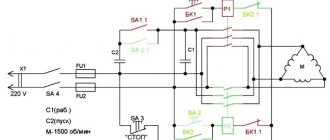
Electrical equipment of the 7M430 slotting machine
The machine is equipped with three electric motors.
- Main drive motor (flange)
- Electric motor for rapid table movement (flange)
- Cooling system electric pump
An electrical cabinet is placed in the niche at the rear of the upper frame. The cabinet doors have a locking device and a sponge rubber seal, which ensures the cabinet's tightness.
The equipment in the cabinet is attached to a steel sheet panel with a getinaks gasket.
The panel is mounted using rigid wire.
The pendant push-button station is mounted on a rubber sleeve to a bracket that can be rotated relative to the stand on which it is mounted; this makes it possible to install the push-button station in any position convenient for the worker.
The local lighting bracket is attached to the left side of the frame to a special plate.
Connections between electrical equipment are made using gas pipes.
Initial start-up of the 7A420 slotting machine
- When initially starting up the 7A420 machine, it is necessary, first of all, to check the reliability of grounding and the quality of installation of electrical equipment by external inspection.
- Using an input machine, the machine is connected to the workshop network.
- Check the operation of the cabinet's blocking and signaling devices.
- Using the buttons, check the precise operation of the magnetic starters.
ATTENTION! When connecting the main motion electric motor, the direction of rotation of the rotor must correspond to the direction of the arrow marked on the casing.
Description of the circuit diagram
The electrical circuit of the machine provides:
- Starting and stopping the main drive electric motor.
- Starting and stopping the electric pump.
- Starting and stopping the electric motor for rapid table movements.
- Remote control of the cutter from a push-button station (start and stop).
- The operation of the table movement counting mechanism.
- Limitation of idling speed of the main electric motor.
- Local lighting of the machine.
1. Starting the engine of the main drive 1M is carried out in the following sequence: by turning the packet switch BB1, a voltage of 380V is supplied from the three-phase alternating current network to the electric motors and control circuit. After pressing the 1KU (start) button, the current flows through the circuit L16-2-3-4-5-6-L26.
The current, having passed through the coil of the magnetic starter 1K, turns on the main contacts 1K at points L12-L13, L22-1S2, L32-Lzz and starts the electric motor of the main drive 1M. At the same time, the magnetic starter bypasses the 1KU button at points 3-4.
To turn off the main electric motor 1M, you must press the 2KU (stop) button, which opens its N.C. contacts at points 2-3 and de-energizes the coil circuit of the 1K magnetic starter.
2. Turning on and off the electric pump 2M is done by turning the packet switch BB2.
3. Starting and stopping the electric motor of accelerated movements “ZM” is carried out by the “ZKU” (start) button, operating in jog mode.
4. Remote control of the cutter from a push-button station can be carried out in two modes - setup and working.
- Work mode. The PC cycle switch at points 9-10 is open. To start the cutter, you need to press the 4KU button, which, with its NO contacts at points 7-8, will close the circuit of the electromagnet EM-2, which, through a gear drive, will turn the hydraulic panel control valve to the “start” position. The dolly will begin to move. To stop the cutter, you need to press the “2KU” button, which with its NO contacts will close the circuit of the electromagnet EM-1 at points L16-10. The latter, through a gear transmission, will turn the hydraulic panel valve to the “stop” position. The goon will stop.
- Setup mode. The PC cycle switch is closed at points 9-10. The cutter is controlled by only one button 4KU, which turns on EM-2 with its NO contacts, and with N. 3. contacts along the L16-7-9-10-L26 circuit turns on the EM1 electromagnet. The cutter can be started only after the main engine has started, when the N.O. contacts L16-7.
5. The final microswitch of the table movement counting mechanism “1KB” is built into the control circuit of the main electric motor “1M”. When receiving a command from the reference mechanism, the limit switch “1KB” opens the circuit L16 2-3-4-5-6-L26 at points L16-2 and de-energizes the coil circuit of the magnetic starter 1K.
6. The idling speed of the main electric motor is limited by the “2KU” button, which has (N. 3.) contacts in the main engine control circuit at points 2-3 and N.O. contacts in the cutter stop circuit at points L16-10. Thus, when the cutter stops, the main engine will also stop.
7. The local lighting lamp is powered by a reduced voltage of 36 V AC from the secondary winding of a 380/36/6 V transformer. In the light bulb circuit “L1” there is a fuse “ZPR” and a switch “VO”. The signal light L is connected to pin 6v through the damping resistance PS.
The signal light L2 lights up when voltage is applied from the network by turning the package switch BB1.
Technical characteristics of the 7M430 slotting machine
| Parameter name | 7403 | 7405 | 7M430 | 7D430 |
| Basic machine parameters | ||||
| Machine accuracy class | N | N | N | N |
| Stroke of the cutter, mm | 120..320 | 120..500 | 120..320 | 120..320 |
| Table diameter, mm | 630 | 800 | 630 | 630 |
| Distance from the table plane to the cutter guides, mm | 500 | 710 | 500 | 500 |
| Distance from the cutter to the frame (reach), mm | 615 | 710 | 590 | 615 |
| Maximum height of the workpiece when processing the outer surface, mm | 500 | 650 | 320 | 500 |
| Maximum height of the workpiece when processing the internal surface, mm | 250 | 325 | 250 | 250 |
| Slotting head of the machine (slotter) | ||||
| Maximum movement of the cutter within the working area, mm | 500 | 700 | 570 | 500 |
| Maximum angle of rotation of the cutter in the direction of longitudinal feed, degrees | 10° | 10° | 10° | 10° |
| Largest cutter section, mm | 32 x 20 | 40 x 25 | 40 x 25 | 32 x 20 |
| Cutter speed under load, m/min | 3..38 | 3..38 | 3..38 | |
| Machine work table | ||||
| Maximum longitudinal movements of the table (along the frame guides), mm | 650 | 800 | 650 | 650 |
| Maximum transverse table movements (along the slide guides), mm | 510 | 650 | 500 | 510 |
| The largest movements of the table are circular, degrees | 360° | 360° | 360° | 360° |
| The cost of dividing the dial for longitudinal and transverse movement of the table, mm | 0,1 | 0,1 | 0,2 | 0,1 |
| Movement of the table per revolution of the dial during longitudinal and transverse movement of the table, mm | 0,7 | 1,4 | ||
| The cost of dividing the dial when moving the table in a circular motion, degrees | 1° | 1° | 1° | 1° |
| Movement of the table per revolution of the dial during circular movement of the table, deg | 0,86° | 0,86° | ||
| Feed limits for one double stroke, longitudinal, mm | 0,1..2,5 | 0,1..2,5 | 0,2..2,4 | 0,1..2,5 |
| Feed limits for one double stroke, transverse, mm | 0,1..2,5 | 0,1..2,5 | 0,2..2,4 | 0,1..2,5 |
| Feed limits for one double stroke, circular, deg | 0,1..1,4° | 0,1..1,4° | 0,1..1,4° | 0,1..1,4° |
| Speed of rapid table movement longitudinal, mm/min | 2,8 | 2,8 | 2,5 | 2,8 |
| Speed of rapid table movement transverse, mm/min | 2,8 | 2,8 | 2,5 | 2,8 |
| Speed of rapid movement of the table circular, rpm | 4,5 | 4,5 | 4,07 | 4,5 |
| Electrical equipment. Drive unit | ||||
| Number of electric motors on the machine | 3 | 3 | 3 | 3 |
| Hydraulic drive electric motor (main movement), kW (rpm) | 11 (970) | 11 (970) | 7 | 10 |
| Electric motor for rapid table movement, kW | 2,2 | 3,0 | 1,7 | 2,2 |
| Coolant electric pump electric motor, kW | 0,12 | 0,12 | 0,12 | 0,12 |
| Total power of all electric motors, kW | 13,32 | 14,12 | ||
| Dimensions and weight of the machine | ||||
| Machine dimensions (length width height), mm | 2850 x 2160 x 3010 | 3440 x 2760 x 3465 | 2650 x 1810 x 2890 | 3030 x 2175 x 3010 |
| Machine weight, kg | 5660 | 8160 | 5200 | 5700 |
- Hydroficated slotting machine 7M430. Manual for the machine, 1961
- Petrukha P.G. Cutting of structural materials, cutting tools and machines, 1974, p. 438
- Yakovtsev A.D. Working on planing and slotting machines, 1966
- Kopylov R.B. Working on planing and slotting machines, 1975
Bibliography:
Related Links. Additional Information
- Hydraulic drive of the 7M430 slotting machine. Typical faults
- Repair of hydraulic systems of metal-cutting machines
- Designations of hydraulic circuits of metal-cutting machines
- Classification of metal-cutting machines
- Selecting the right metalworking machine
- Testing and checking metal-cutting machines for accuracy
- Directory of factories producing metal-cutting machines
- Manufacturers of metal-cutting machines
- Directory of slotting machines
- Articles on the topic
Home About the company News Articles Price list Contacts Reference information Interesting video KPO woodworking machines Manufacturers
Scheme for setting up the feed mechanism of the 7A420 slotting machine
Feed mechanism setup diagram
Feed mechanism
| Number of steps | 1 | 2 | 3 | 4 | 5 | 6 | 7 | 8 | 9 | 10 | 11 | 12 |
| Position of the table feed settings for double stroke, mm | 0,1 | 0,2 | 0,3 | ,04 | 0,5 | 0,6 | 0,7 | 0,8 | 0,9 | 1,0 | 1,1 | 1,2 |
| 0,067 | 0,13 | 0,2 | 0,26 | 0,33 | 0,4 | 0,46 | 0,52 | 0,59 | 0,67 | 0,73 | 0,79 | |
| longitudinal | 0,1 | 0,2 | 0,3 | ,04 | 0,5 | 0,6 | 0,7 | 0,8 | 0,9 | 1,0 | 1,1 | 1,2 |
| transverse | 0,1 | 0,2 | 0,3 | ,04 | 0,5 | 0,6 | 0,7 | 0,8 | 0,9 | 1,0 | 1,1 | 1,2 |
| circular | 0,067 | 0,13 | 0,2 | 0,26 | 0,33 | 0,4 | 0,46 | 0,52 | 0,59 | 0,67 | 0,73 | 0,79 |
Main movement mechanics
| Stage number | Gearbox position | Number of double strokes of the cutter per minute. | Estimated cutting efficiency |
| I | 32 | 0,656 | |
| II | 49 | 0,656 | |
| III | 66 | 0,656 | |
| IV | 101 | 0,656 |
Table of average working speeds V r.h. and nominal traction forces on the cutter depending on the planing length
| Stroke length of the cutter, mm | Stroke angle | Number of double strokes per minute | |||||||
| n=32 | n=49 | n=66 | n=101 | ||||||
| V r.kh. m/min | P kN | V r.kh. m/min | P kN | V r.kh. m/min | P kN | V r.kh. m/min | P kN | ||
| 25 | 185030′ | 1,44 | 58,25 | 2,3 | 36,42 | 3,78 | 22,3 | 5,82 | 14,46 |
| 50 | 191002′ | 2,8 | 30,46 | 4,46 | 19,15 | 7,33 | 11,66 | 11,31 | 7,56 |
| 75 | 196035′ | 4,09 | 21,2 | 6,51 | 13,34 | 10,69 | 8,12 | 16,49 | 5,26 |
| 100 | 202010′ | 5,3 | 16,57 | 8,44 | 10,42 | 13,86 | 6,34 | 21,38 | 4,11 |
| 125 | 207049′ | 6,45 | 13,79 | 10,26 | 8,67 | 16,85 | 5,28 | 26,0 | 3,42 |
| 150 | 213031′ | 7,53 | 11,94 | 11,98 | 7,51 | 19,68 | 4,57 | 30,37 | 2,96 |
| 175 | 219019′ | 8,55 | 10,61 | 13,61 | 6,68 | 22,35 | 4,06 | 34,49 | 2,63 |
| 200 | 225014′ | 9,52 | 9,62 | 15,14 | 6,05 | 24,88 | 3,68 | 38,38 | 2,39 |