08/29/2019 Author: VT-METALL
Issues discussed in the material:
- What is the technology of automatic welding of metal structures
- What is the technology of semi-automatic welding of metal structures
- What are the features of welding aluminum metal structures
- What defects are possible when welding metal structures?
For a long time, metal structures have been connected to each other by welding. This technology is used not only by amateurs at home, but also by professionals on an industrial scale. Welding techniques are constantly being improved, so at present the result shown by the technology of welding metal structures (regardless of their dimensions) is much higher than a couple of decades ago.
Requirements for welding metal structures
The following requirements for the installation of metal structures and welding apply to a greater extent to professional workers, but if a person wants to develop in this business, then it would be a good idea to familiarize yourself with the following information.
For certain types of metal structures, special types of materials are used from which elements of the correct geometric shape are made. It is also important that the strength and weldability characteristics comply with those required by SNIP II 23-81 and GOST 27772-88. This document also contains sections devoted to diagrams of how seams are created correctly and how their quality affects the stability and durability of the entire structure. The complexity of the work depends on the number and shape of the parts.
Download GOST 27772-88
Also an important point is the qualifications of the employee. Since there are types of welding of metal structures that can only be assembled by workers who have long been familiar with this craft, the work of beginners is simply not acceptable. A more detailed list of such structures is regulated by document RD 15.132-96 of the Ministry of Fuel and Energy of the Russian Federation.
Example of welding metal structures
Also, according to GOSTs of the Russian Federation, welding of critical metal structures must be controlled.
Download GOST 5264-80
How to choose electrodes
The main element in metal welding technology is electrodes, which are available in various versions: consumable and non-consumable.
For a beginning student, in order to be able to make high-quality connections of metal structures, it is recommended that in the first approaches only use universal rods with a thickness of 3-4 mm.
Before installation, experts insist on choosing the right type of electrodes and type of metal. The classification distinguishes several types: rutile, basic, acidic, cellulose.
- Cellulose electrodes are intended for welding with alternating current, where it is necessary to obtain a strong seam, for example, when installing load-bearing structures. These electrodes can be used to cook using any method.
- Acidic electrodes are cooked using alternating and direct currents. The only drawback to using such electrodes is the formation of toxic fumes. Therefore, working with them indoors is prohibited.
- Mixed electrodes are used for pipeline welding. This method shows excellent results in a ceiling position.
Classic technology
Classic technology for welding metal structures is based on time-tested methods such as gas-fire and electric welding. In both options, suture methods are divided into:
- Auto.
- Semi-automatic
- Manual.
The automatic method is based on the absence of human physical labor. A special robotic device, depending on the work being carried out, is switched to the correct mode and performs the work, thereby replacing a person. Such units have limitations commented on in their instructions. It is most profitable to use such machines in mass production by companies whose products require a large number of connections.
The manual method implies the presence of physical human labor. This includes control of the welding electrodes and joint formation. Most often, the manual method means:
- Using standard flux welding.
- Soldering of metal structures with a gas welding device.
- Arc welding.
The latter method is popular when working at home for your own needs, or in a small enterprise, since large-scale production will have large costs for maintaining this method of welding structures.
Semi-automatic welding
Semi-automatic - involves manual processing of seams, but the supply of the electrode itself is carried out automatically, which increases labor productivity. And in combination with the human factor and the automatic welding method, the robotic joining method is very popular and has gained development among both amateurs and professionals in this field.
Classical methods for metal structures
Regardless of the method of connecting the rental, there are three modes of performing work:
- auto;
- semi-automatic;
- manual.
Let's take a closer look at them.
Auto
This method reduces human participation in the process to a minimum . The operator’s function is to control the production process, as well as adjust the input parameters, if necessary. Used in large-scale enterprises.
Semi-automatic
The welder's task is to determine the optimal speed of the arc, as well as adjust the direction . The supply of filler material is carried out automatically, according to pre-configured parameters.
Manual
In this case, all operations are performed by the hands of a welder . There are several ways to create a permanent connection. In addition to electric welding, you can perform metal soldering manually, as well as work with gas welding equipment.
Types of welding for assembling metal structures
A major issue is the type of welding used to join the seams. The grade of the steel profile, its composition and thickness are not the only things that matter in the issue of successful seam processing. The type of welding also has a big influence.
The mechanization of production has influenced the choice of shop welding in favor of those based on flux-cored wires or an automatic process that is performed in an environment of inert gases or in layers of flux. The difference in the methods is that the first of them mainly applies to joints of fillet welds located under the ceiling or vertical joints, while the second option is suitable for joining parts in lower positions.
Previously, a very common type of connection was electroslag welding, which is currently practically not used, due to the fact that research by specialists in this field has shown the unreliability of metal structures erected in this way, and that at negative temperatures it loses its strength characteristics.
Manual arc welding
Based on these facts, it can be concluded that in work areas and even in open areas, work can be carried out using any type of welding. It is curious that foreign companies, whose enterprises are equipped with modern automatic machines, still pay more attention to manual arc welding of metal structures. Japan can serve as a serious example, significant enterprises of which use more than 60% of manual welding for the construction of important metal structures.
How to make welds correctly
To perform a weld correctly, firstly, you need to familiarize yourself with the regulatory welding and design documentation. The necessary design documentation is presented in the form of a basic set of drawings of the KM brand, and KMD (metal structures, metal detailing structures). In the album of the KM section you will receive general information about the metal welded structures of the construction site (or part of it):
- General form;
- composition of structures (how many beams, columns, trusses, braces, etc. parts);
- main connection points;
- instructions for performing work;
- information about loads on structures;
- specification of rolled metal.
In the KMD section you will find:
- detailed drawings of each metal element;
- detailed components for connecting elements;
- updated specification of rolled metal products.
Read the notes and instructions for performing work on the drawings. It may contain important points, without which the manufactured metal structure will not meet the requirements applied to it.
Assembly and welding of elements must be carried out only if there is a documented technology for welding work for this structure.
Documentation is carried out in the form of technological maps and (or) a production project (PPSD) for welding work. They reflect in detail all questions about the process and materials.
Temperature conditions of the welding process
Air temperature has a great influence on the choice of the technology used to create a seam and on its quality.
The fact is that it is impossible to carry out work on the construction of metal structures if the temperature of the workpieces themselves drops below - 18 ° C. In such conditions, the temperature must be monitored by measuring the area where the two parts join. And if it turns out to be below critical, the workpieces themselves undergo heat treatment before creating the seam. Not the entire element is heated, but only at a short distance from the edge, equal to the thickness of the workpiece, or at a distance of at least 75 mm in any direction.
If a seam must be created between parts made of different alloys, then both are heated according to the temperature regime of the strongest of them (in terms of material strength). Do not forget also that the heating temperature depends on some characteristics of the material itself.
As an example, use steel grade A514, the blade of which, with a thickness exceeding 40 mm, requires heating to 210 °C. Thicker parts made from this steel are heated to 235 °C.
Technological cards
The welding flow chart includes a number of points and graphs indicating the following characteristics of the welding process of metal structures:
- product name;
- units of measurement of the volume of work performed;
- digital code of the operation being performed;
- designation of the standards on the basis of which it is implemented;
- automation level, operator qualification code and many other parameters.
The contents of a typical technological map can be found in the Table
The main purpose of this scientific document is to record all the information about the completed operation for the construction of metal structures and store its codes in a computer database as a standard sample.
Based on these maps, enterprises and organizations prepare and constantly update information arrays that make it possible to quickly refer to a previously implemented technological process.
All information specified in the cards is entered into the database only in encoded form.
When developing a new technology for welding metal structures, it is taken into account after an expert assessment of the effectiveness of upcoming operations is carried out (based on the characteristics of individual prefabricated products).
Quantitative assessment of the manufacturability of these operations is carried out taking into account the following factors:
- the sequence of their implementation;
- breakdown of metal structures into independent technological units;
- types of equipment and special devices used;
- current welding modes, expected stresses in the structure and the degree of deformation of individual components.
Upon completion of testing the effectiveness of the new welding process chain, the data and codes are sent for storage to the enterprise computer database.
Welding structures - features
The very concept of welding applies not only to products made of metal alloys, but also to products made of polymers, that is, for example, plastic. After all, this concept implies a thermal processing process in which two or more parts are combined into a single component.
The work itself is divided into two steps - assembly and connection. The first one has the greatest labor intensity.
After all, in order for the quality of the erected metal structure to be durable, it is necessary that all the stated requirements for the workpieces and the material from which they were made were observed until the end of the work.
Welding work
From an objective point of view, more than half of the entire work period is spent on the assembly of the future metal structure.
Metal welded trusses
Welded steel trusses are a flat lattice system of metal elements that allows you to span large spans of buildings and structures.
A truss is a structural element of a building that serves to support the roofing system (purlins, decking, roofing pie) and transfer the load from it to columns or walls.
Metal trusses are often used in the construction of industrial buildings, since the technological process often does not allow the installation of intermediate racks.
Also, steel trusses are most widely used in the construction of social and administrative buildings. Such as: shopping centers, cinemas, stadiums, swimming pools and many others.
It is such buildings that are characterized by the presence of large free internal space. The metal welded truss consists of:
- Knots of the upper belt.
- Raskosov.
- Stoeck.
Braces, in turn, are divided into supporting and ordinary. Support braces are located at the point where the truss is supported. They carry heavy loads, so their cross-section is often larger than that of ordinary braces (or the grade of steel is higher).
Farms can be homogeneous or combined. Because they can combine elements made from different grades of steel.
It is combined metal structures that are an effective solution; their use is most rational in cases where the loads on the elements are significantly different. The braces, as well as the truss posts, are connected to the lower as well as the upper chord directly or using gussets. Their elements can be made from:
- Square pipe.
- Rectangular pipe.
- Round pipe.
- Corner.
- Various profiles.
Steel trusses are the most common solution. Trusses are developed for a specific construction project or selected according to a series, having performed the appropriate calculations.
Truss drawings are developed in the KM and KMD section, where basic instructions for the production and installation of structures are also prescribed.
Ensuring Correct Assembly
Ensuring high-quality completion of work is also based on correct adherence to a certain list of rules for the assembly of metal structures:
- When selecting the parts that will make up the metal structure, you should adhere to the drawings that were outlined when drawing up the project. Otherwise, the minimal losses will be a discrepancy in the appearance of the structure, and in the worst case, it will not be able to perform the functions assigned to it.
- Based on the project plan, each element must be in its place.
- The width of the gaps plays an important role in the construction of structures. If they end up having larger dimensions than they were supposed to, then this fact will greatly affect the strength of the product. But in turn, too small gaps can negatively affect the proper operation of moving parts.
- Any structure has corners, the level of which must be controlled using special tools. Where this is required, the angles must be exclusively straight, otherwise this will greatly affect the position of the structure and cause it to skew, or even lead to complete destruction.
- Butt joints must be provided with gaps with sufficient space for permissible backlash of elements.
- Throughout the construction of the entire structure, these points must be taken into account. Especially in the case of automatic welding, because with manual technology the worker can control and adjust the direction of the part, which is almost impossible to do when using automatic devices. But at the same time, robotic intervention in welding virtually eliminates errors caused by the human factor.
Auxiliary equipment
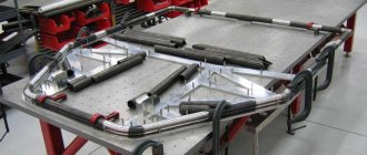
It is impossible to weld structures of significant dimensions without the use of auxiliary devices, with the help of which the assembly elements are fixed, as well as their delivery to the installation site.
The main accessories for welding metal structures are:
- Conductor . Ensures the stationary position of rolled metal during its installation. There are various ways to implement these devices. As a rule, their appearance resembles a stand or frame. The simplest design for home work is a device for joining welded elements at right angles.
- Slipway . It is a lifting device that acts as a support mechanism in construction and installation work. The use of slipways allows you to increase the productivity of working with prefabricated structures.
Positive aspects of welding
In addition to reducing working time and quality, welding has a positive effect on other characteristics:
- Due to the fact that during the welding process only two elements are involved, excluding the influence of other factors, the final soldering in mass does not differ in any way from the original version, which in turn allows saving the amount of material.
- Due to its characteristics, welding is almost completely devoid of restrictions in work due to the material thickness factor. All responsibility for this shifts only to the use of certain equipment.
- A variety of modern welding machines make it possible to carry out joining work with almost any material without loss of seam strength, even taking into account the factor of manipulating such a complex material as aluminum.
- A significant positive aspect of using welding is saving money and working time.
- The heavier the type of welding, the more complex the type of structure can be. It also makes it possible to use elements made by stamping or cast in molds. In this case, the material from which they are made does not play a special role.
- Welding units presented on today's market are quite affordable, and if you use the right technique, you can increase the production speed factor.
- If there is an opportunity, as well as the desire of the enterprise, to erect structures in the assembly of which non-standard materials will be used, welding will help to easily carry out this task.
- Welding is more than applicable even for working with very small parts.
- Welding for the purpose of repairing or bringing mechanisms into working condition is also very appropriate.
- When welding is used, each structure will have absolute tightness. Of all the available methods of connecting joints, welding has the highest reliability indicator for this parameter.
Nuances: what needs to be taken into account during preparation and assembly
Often during assembly, inexperienced welders encounter problems:
- the structure is severely deformed . The main reasons are associated either with incorrect assembly or with a violation of welding technology - the current chosen is too high, the sequence of welding of the elements is broken;
- the flat part is guided by a “screw” . To prevent this, you need to scald the part slowly. For example, first one corner of the frame (one seam), then - diagonally - the second (one seam) and so on in a circle, turning the structure from one side to the other. It is also possible to fix the product on a flat surface with clamps and clamps;
- After assembly, the potholders break . Reasons: low current or mistakes made during welding. It is necessary to reassemble the structure;
- There is not enough voltage in the network, the electrode constantly sticks - changes often appear outside the city. The situation can be improved if all consumers are temporarily turned off: kettles, microwave ovens, refrigerators, air conditioners.
Sometimes it turns out that the welded metal structure does not fit into place. This happens when the assembler did not take into account the gaps that are installed for better welding of the seams.
To assemble large volumetric metal structures, it is recommended to use temporary reinforcements - corners, channels, which should help keep the dimensions within the given limits.
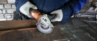
For example, when installing vertical posts, jibs are welded onto the main frame to hold them in place. After scalding, they are cut with a grinder.
Welded joints and their types
Welded joints are classified according to the presence of one of the following characteristics:
- Location of connection of 2 parts.
- Type of weld used.
- Welding technologies used in connection.
- The environmental conditions under which the process itself was carried out
- According to the thickness of the parts.
- The grade of alloy from which the parts are made.
Aluminum weld
Regarding the first point of the plan, the details, according to their geometric location, have four types of connections:
- Butt joint, single-plane connection of two workpieces.
- Overlapping, when the workpieces are welded by placing the edge of one part on the edge of another.
- Corner joints - joining parts at a certain angle.
- T-joint. Welding when a part is adjacent to another end plane.
Butt joints are made by welding along the thickness of the element or when creating a seam on the lead strips. If the welding process is carried out outside the workshop room, then the connection can be organized by one-sided welding, with further welding of the base of the seam, which implies filling the space between the elements, carried out along one of the edges.
The work based on output pads is radically different from the previous one. The lining should be adjacent to the edge of the parts being joined - this is it. The resulting space should measure no more than 6 mm. This condition applies to the manual welding method. If the work is performed mechanically. Then it should not exceed 15 mm. The pads are selected based on the thickness parameter so that the part does not burn through during the working process.
Titanium weld
In erected structures based on butt joints, blanks made of different thicknesses are often combined. In this case, a processing method is used in which the angle of inclination of steel with greater thickness is reduced, which should correspond to 1/8 of the inclination of stretched metal workpieces, or 1/5 for compressed elements.
Connections
Over the period of existence of welding technology, many joining methods have been developed. The main parameter that is paid attention to is the relative position of the welded elements after completion of the work. The following types of metal structure connections are found:
- end-to-end;
- overlap;
- corner;
- T-bar;
In addition to the type of connection, important factors are the welding equipment used, the thickness of the elements, and the type of base metal.
Welded components in metal structures
All structures made of metal are supported on a base of welded joints, which are the basis of butt joints. When developing a project, engineers must take into account convenient conditions for high-quality work in these units. These include:
- The condition is that the nodes be welded with a corner or butt joint.
- The lower welding position has priority.
- Mainly use mechanized or fully robotic welding to ensure the quality of the work performed.
There are many subspecies among connecting nodes, most of which have different requirements. A good example would be a beam assembly. In it, the greatest attention is concentrated on the distance between the welds, since it should not be shorter than the thickness of the thickest steel element divided by 10 that is part of this assembly.
Total information
Metal structures are used everywhere: industrial and civil buildings, production facilities and equipment, parts of transport routes, etc. There are different ways to connect metal structures, they are distinguished:
- Rivet connections;
- bolted connections;
- welded joints;
Welding is becoming a common solution when choosing a method for connecting metal elements, since a welded structure has a number of advantages:
- Relative ease of manufacture;
- High speed of work;
- Large selection of materials and equipment for welding;
- Ability to create structures of complex configuration;
- Creation of an equally strong hermetic connection;
- Connection of metal meshes and reinforcement cages.
Let's talk in more detail about welded metal structures.
Welding services at low prices
In what cases can specialists with an excellent reputation still offer a comfortable cost per ton for welding metal structures? Just when they have already achieved everything and there is no need to prove anything to anyone. Our workshop has everything to do your job efficiently:
- modern equipment,
- the skillful hands of our professionals,
- own areas for the execution of any projects.
We can answer the question of how much it costs to weld a ton of metal, and we are ready to come to your site if welding metal structures on our site is impossible due to their size.
Manual arc welding technology
Manual arc welding is performed using welding electrodes, which are manually fed into the arc and moved along the workpiece. During welding with a coated metal electrode, an arc burns between the electrode rod and the base metal. The electrode rod melts and the molten metal flows in drops into the metal bath. Together with the rod, the electrode coating melts, forming a protective gas atmosphere around the arc and a liquid slag bath on the surface of the molten metal. The metal and slag pools together form the weld pool. As the arc moves, the weld pool hardens and a weld seam is formed. Liquid slag after cooling forms a solid slag crust.
Electrodes for manual welding are rods with coatings applied to them. The rod is made from high quality welding wire. Welding wire of all brands, depending on the composition, is divided into three groups: low-carbon, alloyed and high-alloyed.
Manual welding is convenient when making short and curved seams in any spatial positions (Fig. 1) - bottom, vertical, horizontal, ceiling, when applying seams in hard-to-reach places, as well as during installation work and assembling structures of complex shapes. Manual welding produces good quality welds, but has lower productivity, for example, compared to automatic submerged arc welding.
Rice. 1. Types of welds
The performance of the process is mainly determined by the welding current. However, the current during manual welding with coated electrodes is limited, since increasing the current above the recommended value leads to heating of the electrode rod, peeling of the coating, severe spattering and waste of molten metal.
Mode selection. The welding mode is understood as a set of controlled parameters that determine the welding conditions.
The diameter of the electrode is selected depending on the thickness of the metal, the leg of the weld, and the position of the seam in space.
The approximate relationship between the metal thickness S and the electrode diameter dе when welding in the lower position of the seam is:
| Metal thickness, S, mm | 1—2 | 3—5 | 4—10 | 12—24 | 30—60 |
| Electrode diameter, de, mm | 2—3 | 3—4 | 4—5 | 5—6 | 6—8 |
The current strength mainly depends on the diameter of the electrode, but also depends on the length of its working part, the composition of the coating, and its position in the welding space.
The higher the current, the greater the productivity, i.e., the greater the amount of deposited metal:
Q = αнIсвt ,
where Q is the amount of deposited metal; αн — deposition coefficient, g/(Ah);
Iw—welding current, A; t — time, h.
However, if the current is excessive for a given electrode diameter, the electrode quickly overheats beyond the permissible limit. This leads to a decrease in seam quality and increased spattering. If the current is insufficient, the arc is unstable, often breaks, and the weld may lack fusion. The current value can be approximately determined using the following formulas:
when welding structural steels for electrodes with a diameter of 3-6 mm:
Id = (20 + 6de)de; for electrodes with a diameter of less than 3 mm:
Id = 30dе,
where de is the diameter of the electrode, mm.
Welding seams in vertical and overhead positions is usually performed with electrodes with a diameter of no more than 4 mm. In this case, the current strength should be 10-20% lower than for welding in the lower position. The arc voltage varies in a relatively narrow range of 16-30 V.
Welding technique. An arc is a powerful, stable discharge of electricity in an ionized atmosphere of gases and metal vapors. Ionization of the arc gap occurs during arc ignition and is continuously maintained during its combustion. The arc ignition process in most cases includes three stages: short circuit of the electrode to the workpiece, withdrawal of the electrode and the occurrence of a stable arc discharge.
The arc can be excited in two ways: by touching the end of the electrode to the workpiece and moving it away from the workpiece perpendicularly upward at a distance of 3-4 mm (Fig. 2), or by quickly lateral movement of the electrode to the workpiece being welded and moving the electrode away from the workpiece (“striking” the electrode on the workpiece , like lighting a match). The contact of the electrode with the product must be short-term, otherwise it will be welded to the product. The second method is more convenient, but is unacceptable in narrow and inconvenient places.
Rice. 2. Arc ignition methods : a - lateral movement; b - touching the electrode
During the welding process, it is necessary to maintain a certain arc length, which depends on the brand and diameter of the electrode. Approximately normal arc length should be within
Ld = (0.5 - 1.1)de,
where Ld is the length of the arc, mm; de—electrode diameter, mm.
The length of the arc significantly affects the quality of the weld. A short arc burns steadily and ensures a high-quality weld, since the molten metal quickly passes through the arc gap and is less subject to oxidation and nitriding. In addition, long-arc welding with basic-type coated electrodes leads to porosity of the weld metal. To correctly form a seam when welding with a consumable electrode, it is necessary to hold the electrode inclined in relation to the surface of the metal being welded, at an angle of 15-20° from the vertical line. By changing the angle of inclination of the electrode, you can regulate the depth of fusion of the base metal and influence the cooling rate of the weld pool. In Fig. Figure 3 shows the effect of the inclination of the electrode and the inclination of the welded product on the depth of penetration of the base metal.
Rice. 3. The influence of the inclination of the electrode and the inclination of the welded product on the depth of penetration of the base metal : a - forward angle welding; b - backward angle welding; c - welding with a vertical electrode downhill; d - welding with a vertical electrode on the rise; d - welding with a vertical electrode on a horizontal surface
In addition to the arc length, the quality of the weld is also affected by the magnitude of the welding current, voltage and welding pace. The appearance of the resulting weld when deviating from normal conditions is shown in Fig. 4.
Rice. 4. Dependence of the weld on voltage, current and welding rate
During the welding process, the electrode moves in three directions.
- The first movement is translational, in the direction of the electrode axis. This movement maintains a constant (within certain limits) arc length depending on the melting rate of the electrode.
- The second movement is the movement of the electrode along the axis of formation of the weld bead. The speed of this movement is set depending on the current, the diameter of the electrode, the speed of its melting, the type of seam and other factors. In the absence of transverse movements of the electrode, a so-called thread roller is obtained, 2-3 mm wider than the diameter of the electrode, or a narrow seam with a width of e = 1.5 dе.
- The third movement is to move the electrode across the seam to create a seam wider than the thread bead, the so-called widened bead.
The transverse oscillatory movements of the end of the electrode are determined by the shape of the groove, the size and position of the seam, the properties of the material being welded, and the skill of the welder. Wide seams (e = (1.5 – 5)dе) are obtained using transverse vibrations shown in Fig. 5. Using the example of these basic oscillatory movements in table. 1 shows the movements of the electrode during various types of welding.
Rice. 5. Scheme of movement of the end of the electrode during manual electric arc welding
When welding thin sheets, apply a narrow bead (0.8-1.5 width of the electrode diameter) without transverse vibrations. In other cases (when welding thick sheets), widened beads are used. Oscillatory movements improve heating of the weld edges, slow down the cooling of the deposited metal pool, ensure a uniform weld and eliminate lack of penetration of its root.
Table 1. Examples of electrode movement for various types of welding
| Name of movements | Movement pattern _________________________________ | Purpose |
| Reciprocating motion in one plane | Used to obtain a weld bead with high-performance electrodes in all positions and for all types of joints | |
| Cyclic movement of the electrode | Used for root welding of fillet welds and V-shaped grooves with high-performance electrodes | |
| Straight-line zigzag movement of the electrode in the vertical plane | Used with all types of electrodes for filling vertical corner and V-groove seams, sometimes used for facing seams. With low-hydrogen electrodes used for root welding of fillet welds and V-shaped grooves | |
| Triangular electrode movement | Used for facing seams. With low-hydrogen electrodes it is used for welding the root of fillet welds and V-shaped grooves | |
| Reciprocating motion with vertical displacement between passes | Suitable for use with all types of electrodes for filling vertical corner and V-shaped joints. At the end of the horizontal movement, on both edges, the electrode has a fixed delay, then moves upward slightly | |
| Movement with overlap and slight rocking of the electrode around the weld pool | Used with all types of electrodes for welding ceiling seams, sometimes during cyclic movement the crater overlaps | |
| Straight-line zigzag movement of the electrode in the horizontal plane | Can be used with all types of electrodes in wide V-shaped grooves in the down position |
Butt welding without cutting edges is carried out mainly by through penetration on one side of the seam. In these cases, it is recommended to use pads (steel, copper). Sometimes, when possible, the seam is welded with a narrow bead on the reverse side.
Parts for welding are assembled in fixtures, most often with tacks. The cross-section of the tack weld is approximately 1/3 of the cross-section of the main weld, its length is 30-50 mm. Fillet welds are welded “in a corner” or “in a boat” (Fig. 6).
Rice. 6. Position of the electrode and the product when making fillet welds : a - welding in a symmetrical “boat”, b - in an asymmetrical “boat”, c - “in the corner” with an inclined electrode, d - with melting of the edges
When forming a fillet weld (Fig. 6, a, b, c), the electrode is placed at an angle of 45° to the surface of the part. Using increased current values, in order to avoid lack of weld penetration, both surfaces to be welded are tilted to the horizontal plane at an angle of 45° (boat welding, Fig. 6, a). When the surfaces to be welded are tilted at an angle of 30° or 60° - into an asymmetrical boat.
When welding “in the corner”, assembly is simpler, a large gap between the parts being welded is allowed (up to 3 mm), but the welding technique is more complex, defects such as undercuts and sagging are possible, productivity is lower, since it is necessary to weld seams of a small section in one pass (leg < 8 mm) and use multilayer welding. Boat welding is more productive, allows for larger seam legs in one pass, but requires more careful assembly.
When butt welding a seam with a V-shaped groove (Fig. 7, a), the arc is ignited near the bevel of the edges and a metal bead is deposited. Depending on the thickness of the sheet and the diameter of the electrode, the seam is performed in one or several passes.
When multilayer welding, each layer is thoroughly cleaned. The number of layers is determined based on the diameter of the electrode. The layer thickness is (0.8 ÷ 1.2)del.
Welding X-shaped seams (Fig. 7, b) in order to reduce deformation is carried out by alternately applying layers on both sides of the groove.
Rice. 7. Butt welding with edge preparation : a - diagram of the application of metal beads with a V-shaped edge preparation; b - butt welding with double-sided cutting of edges.
The assembly of parts in preparation for welding, cutting of metal edges and gaps between parts during butt welding, according to GOST, are shown in the figures in table. 2, as well as in Fig. 8-11.
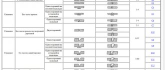
Table 2. Main types and sizes of structural elements of the seam
| Type of welds according to GOST | Name of welded joint | Type of structural elements | Welded joint | Size of structural elements | ||
| — | With flange | — | S=1÷3 | |||
| C2 | Butt joint without bevel edges, double-sided | S=S1 | b | a | ||
| 3÷3,5 | 8±4 | 1+0,5-1,0 | ||||
| 4÷4,5 | ||||||
| 5÷5,5 | 9±4 | |||||
| 6÷8 | 2+1,5-1,0 | |||||
| h=2÷3 | ||||||
| C3 | Butt joint without bevel edges, one-sided | |||||
| C8 | Butt V-shaped with bevel of two edges, double-sided | S=S1 | b | S2 | ||
| 3÷8 | S+11 | 1±1 | ||||
| 9÷14 | S+13 | 2+1,0-2,0 | ||||
| 15÷21 | S+15 | |||||
| C9 | Butt V-shaped with bevel of two edges, one-sided | 22÷26 | S+16 | |||
| b1=10±4; h=3÷4 | ||||||
| C11 | Butt V-shaped with a curved bevel of two edges, double-sided | S | b | h | ||
| 20÷23 | S+9 | 0+5 | ||||
| 24÷29 | S+7 | |||||
| 30÷33 | S+4 | |||||
| 34÷41 | S | |||||
| 42÷49 | S-3 | |||||
| 50÷55 | S-7 | |||||
| 56÷60 | S-12 | |||||
| b1=10±4 | ||||||
| C15 | Butt X-shaped with two bevels of two edges side-by-side symmetrical | S | b | h | ||
| 12÷17 | S+3 | 3 | ||||
| 18÷29 | S+1 | 4 | ||||
| 30÷44 | S-3 | |||||
| 42÷50 | S-8 | |||||
| 51÷60 | S-11 | 5 | ||||
| Type of welds according to GOST | Name of welded joint | Type of structural elements | Welded joint | Size of structural elements | ||
| C17 | Butt X-shaped with two curved bevels of two edges, double-sided | S | b | h | ||
| 30÷35 | S-3 | 4 | ||||
| 36÷41 | S-7 | |||||
| 42÷51 | S-12 | 5 | ||||
| 52÷60 | S-24 | |||||
| U4 | Corner without bevel edges, double-sided | S=2÷30; S1=2÷30 | ||||
| U5 | Corner without bevel edges, one-sided | S=1÷30; S1=2÷30 | ||||
| U7 | Corner with bevel of one edge, one-sided | S | b | |||
| 4÷7 | S+11 | |||||
| 8÷11 | S+13 | |||||
| 12÷17 | S+15 | |||||
| 18÷26 | S+18 | |||||
| h=3÷4; S1≤S | ||||||
| U10 | Corner with bevel of two edges, one-sided | S | b | |||
| 12÷14 | S+12 | |||||
| 16÷21 | S+14 | |||||
| 22÷26 | S+15 | |||||
| h=4; S1=S | ||||||
| T1 | T-type without bevel edges, double-sided | S | K | |||
| 3÷6 | 3÷4 | |||||
| 7÷9 | 5 | |||||
| 10÷30 | 6÷8 | |||||
| Type of welds according to GOST | Name of welded joint | Type of structural elements | Welded joint | Size of structural elements | ||
| T8 | T-bar with bevel of one edge, double-sided | S | b | h | ||
| 4÷7 | S+9 | 3±3 | ||||
| 8÷11 | S+11 | |||||
| 12÷17 | S+13 | 4±3 | ||||
| 18÷26 | S+16 | 5±3 | ||||
| T9 | T-bar with bevel of one edge, single-sided | b1=3 | ||||
| T10 | T-bar with bevel of two edges, double-sided | S | b | h | ||
| 12÷17 | S+2 | 3±3 | ||||
| 18÷25 | S | 5±3 | ||||
| 26÷35 | S-2 | 6±3 | ||||
| 36÷47 | S-3 | 9±3 | ||||
| 48÷51 | S-4 | 11±3 | ||||
| 52÷60 | S-5 | 13±3 | ||||
| H2 | Lap without bevel edges, double-sided | S=2÷60; k=S | ||||
| H3 | Overlapping with electric rivets | S≥2; d≥2S | ||||
| H4 | Overlapping with electric rivets | S≥2; m≥2S | ||||
Butt welding of sheets of different thicknesses is shown in Fig. 8. The connection of overlapping sheets with frontal seams is shown in Fig. 9.
The connection of sheets with overlapped flank seams and reinforcement with slotted seams is shown in Fig. 10.
The butt connection of sheets with overlays is shown in Fig. 11. The overlays are welded to the sheets using frontal and flank seams (the middle projection is common to both joints).
Rice. 8. Cutting edges of sheets of different thicknesses for butt welding
Rice. 9. Joining sheets with overlapped frontal seams
Rice. 10. Joining sheets with overlapping flank seams, reinforced with slotted seams
Rice. 11. Joining sheets end-to-end with one overlay (a) and the same, with two overlays (b)
To increase the performance of welded structures and reduce internal stresses and deformations, the order of filling the seams is of great importance. The order of filling seams means both the order of filling the seam cut along the cross section and the sequence of welding along the length of the seam.
According to their length, all seams can be divided into three groups:
- short - up to 300 mm;
- medium - 300-1000 mm;
- long - over 1000 mm.
Depending on the length of the seam, the material, the requirements for accuracy and quality of welded joints, welding of such seams can be performed in various ways (Fig. 12).
Rice. 12. Welding patterns : a - pass-through; b - from the middle to the edges; c - back in a stepwise manner; g - blocks; d - cascade; e - slide; A - direction of filling the groove: (arrows indicate the direction of welding); 1-5 welding sequence in each layer
Short seams are made as a pass - from the beginning of the seam to its end. Medium-length seams are welded from the middle to the ends or back using a stepwise method. Long-length seams are made in two ways: from the middle to the edges (in a reverse stepwise manner) and scattered.
With the reverse step method, the entire seam is divided into small sections 150-200 mm long, and in each section welding is carried out in the direction opposite to the general welding direction. The length of the sections is usually from 100 to 350 mm. Depending on the number of passes (layers) required to complete the design section of the seam, single-pass (single-layer) and multi-pass (multilayer) seams are distinguished.
From a productivity point of view, the most appropriate are single-pass welds, which are usually used when welding metal of small thicknesses (up to 8-10 mm) with preliminary cutting of the edges.
Welding of connections of critical structures of large thickness (over 20-25 mm), when volumetric stresses appear and the risk of cracking increases, is carried out using special techniques: filling the seams with a “slide” or “cascade” method.
When welding “slide”, first the first layer of short length 200-300 mm is deposited into the groove of the edges, then the second layer overlaps the first and is twice as long. The third layer overlaps the second and is 200-300 mm longer than it. The layers are fused in this way until the groove is filled in a small area above the first layer. Then, from this “hill”, welding is carried out in different directions using short seams in the same way. Thus, the welding zone is in a hot state all the time, which helps prevent the occurrence of cracks. The “cascade” method is a type of slide.
When welding horizontal seams on a vertical plane (Fig. 13, a), only the top sheet is cut, the arc is excited at the bottom edge, then gradually moves to the beveled top edge.
Vertical seams are more difficult to weld due to the molten metal flowing down. To reduce the flow of metal, work is carried out with a short arc and in the direction from bottom to top (Fig. 13, b), with the exception of sheets up to 1.5 mm thick.
Welding ceiling seams (Fig. 13, c) is carried out with a very short arc, during which the electrode short circuits to the part. Electrodes with a refractory coating are used, which forms a “sleeve” around the electrodes containing a directed gas flow that holds the electrode metal.
Rice. 13. Schematic representation of the work when performing welding with various seams : a - horizontal seam on a vertical plane; b - vertical seam; c - ceiling seam. 1—3 — position of the electrode in space; 4 — electrode coating
Ensuring regulatory requirements for welding technology and techniques is the main condition for obtaining high-quality welds. Deviations of the size and shape of the weld from the design ones are most often observed in fillet welds and are associated with violation of welding conditions, improper preparation of edges for welding, uneven welding speed, as well as untimely control measurements of the seam.
831
Prices for the production and installation of metal structures - cost of work
However, not everyone is interested in the metal welding services offered by “garage craftsmen.”
Most customers understand: the lower the price for welding metal structures, the greater the catch hidden in it. The cost of metal welding cannot be prohibitively low. After all, any company with experience and reputation will take into account the volume of the order, the qualifications of specialists, the type of welding and the cost of consumables. This is an objective minimum; in reality, calculating the cost of welding metal products is much more complicated.
How to weld metal structures with your own hands?
Professional welders will confirm that a modern master must be able to manufacture any type of metal structures.
Moreover, there are truly many types; enterprises and individuals often order the production of thick-walled structures. Therefore, any self-respecting welder should know how welded structures are manufactured. In this article, we will briefly describe what types of welded metal structures there are, what the technology for welding metal structures is, and what features should be taken into account in order for your work to be appreciated.
Types of metal structures
There are different types of welded structures. The most popular are beams. Welding of I-beams is the most frequently requested service. Remember that the beams must be rigidly connected to each other. This is the basic requirement.
The second type is columns. Columns must withstand compression well. In general, column welding is as popular a service as I-beam welding. There are also lattice metal structures. To weld lattice structures, you need to make sure that they can withstand significant tension. This type includes a mesh of reinforcement, a metal frame or a truss.
Additionally, shell metal structures are distinguished. Often these are pipelines and various containers. The main requirement for them is absolute tightness and resistance to high pressure. Don't forget about metal frame structures. These include train sets and car bodies. The main requirement is resistance to permanent dynamic loads.
As you understand, each type has its own requirements. They definitely need to be taken into account. You cannot do work “at random”, based only on your own considerations. It is necessary to take into account the environment in which the metal structure will be used and the loads it must withstand.
Metal structure welding technology
The manufacturability of welded structures is not that complicated. Everything is simple here: the technology for connecting parts for a particular metal structure depends on the welding method you choose. For example, you will be welding metal structures with a semi-automatic machine. To do this, you need a semi-automatic device, protective gas in cylinders, filler wire and electrodes.
This approach is appropriate regardless of what kind of structural welding you need. You may be tasked with welding I-beams or box structures. In any case, rely on the features of the welding method you choose. However, there are some tips that are suitable for any type of welding of metal structures. We will share them in detail below.
Selecting a welding method
Now that you know the classification of welded structures, it will be easier for you to choose the type of welding. I can say with confidence that the assembly of metal structures can be carried out using any equipment.
For example, welding of building structures is often performed using a semi-automatic machine. This is not surprising, because semi-automatic welding of metal structures is simple and convenient, it saves time and resources.
We recommend choosing a welding method based on your skills, working conditions and quality requirements.
Welding mode selection
To properly weld metal structures, you need to set up your welding machine. Simply put, select the welding mode. There is only one recommendation: try to maintain the golden mean. There is no need to set the current too high in hopes of getting the job done faster. And you don’t need to cook at low current simply for fear of ruining the seam.
Welding critical metal structures (for example, I-beams) requires maximum concentration and experience from you. Therefore, rely on your own strength and set the settings recommended by GOST for each welding method. As for speed, try to weld about 20 meters of seam per hour. This is the average value.
Temperature selection
Welding of structures must be carried out at a metal temperature of at least 17 degrees Celsius. This is especially important if you plan to manufacture welded structures with increased requirements for the quality of seams (for example, the welding of beams mentioned above). Warm up the area of the future seam to 20 degrees before starting work.
Selecting the type of welded connection
In most cases, butt and corner joints are chosen for welding metal structures. Let's talk about each of them in more detail.
The butt seam must be welded evenly along the entire length and thickness of the metal. This is the optimal method. You can also weld a seam on one side, and then weld the root of the seam on the other side. This is especially true if lattice structures are to be assembled and welded.
With fillet welds everything is more complicated. They are more susceptible to deformation than butt joints, since they are not able to withstand such large loads. If you have the opportunity to replace the fillet weld with a T-weld, then do so. It is also prohibited to use a one-sided fillet weld when connecting thick-walled structures. Double-sided stitching is required.
Assembly and welding of metal structures also requires an understanding of the loads the product will be subject to. If there is a lot of static load, then cut the edges in a K-shape.
Welding Features
Firstly, before work you must have drawings of welded structures on hand. It would be even better if there was a full-fledged package with technical documentation. Technicians must determine which type of welding is best suited and select the optimal types of welded joints.
Welded metal structures contain many components, and each has its own requirements. For example, when welding joints of metal structures, the distance between the seams should be no more than 10 times the thickness of the metal profile itself. This is especially important when connecting beam structures. There is one more feature.
Professionals often use the terms local strength and fragility. Local strength is the nodes to which stiffeners were welded, for example. And fragility means holes in metal profiles, unwelded seams, large gaps between parts, and so on.
It is believed that if both of these shortcomings are noticed in a design, then the product can no longer be called durable.
Therefore, if you have to manufacture welded structures, try to avoid the “sores” mentioned above. Even if you decide that a lower-quality seam can be made in an uncritical area, then you are mistaken. Ultimately, it is this error that will lead to the destruction of the entire structure. Welding of structures does not forgive even minor defects.
Instead of a conclusion
The manufacturability of welded structures lies only in the variety of welding methods. The direct welding process (also known as the technological process) and the production of welded metal structures is not as difficult as it might seem at first glance.
Electrode installation
There are two cables in the structure of the inverter, in the first there is a clothespin - clamp, in the second - a holder for the electrode. Before turning it on, you need to unscrew the head on the handle near the screw holder, install the electrode, and after fixing, screw the head into place.
During the entire welding procedure, it is necessary to hold the electrodes in relation to the coating being welded at an angle of 70-80 degrees, the welding line should be at 90 degrees. This arrangement will create a high-quality, durable seam.
How to cook properly
After turning on the welding machine, the heat energy is redistributed in the direction from the electrode to the metal structure, as a result of the influence of the current, a high-voltage voltage is formed, the metal heats up to high temperatures, thereby acquiring a semi-liquid phase. In connection with this, an effect appears - a weld pool. The electrode substance enters into a chemical-physical bond with the metals, excess slag is formed, which turns into a durable surface that protects the seam.
To correctly form an arc between the adjacent electrodes, you need to turn on the equipment and run the electrode across the metal coating at an angle of 60 degrees until sparks form, then lift the holder at a distance of 5 mm from the part, resulting in the formation of an electric arc, which must be present from the very beginning of the process until completion of work. To maintain tension in the arc, it is recommended to maintain a distance of 5 mm and follow an equal speed throughout the melting section.
As a result of the contact of two differently charged elements, where the minus is the electrode, the plus is the metal structure, a high-voltage flow of current energy is formed, which melts the product, which makes it possible to obtain a strong connection. The welding process should not stop for a minute. This rule must be followed to ensure that the seam is even.
A similar option for welding metal structures is forging. The method is often used by the basics, first-class masters. Screws and bolts are required. This method is performed if the characteristics of the metal are not suitable for welding.
It should be remembered that welding is considered a hazardous activity where eye protection is important. Without a mask, even a highly qualified master will not be able to get the desired result. Compliance with the conditions of work performance is a secondary, important factor where it is necessary to strictly adhere to all requirements.
