If the verification reveals any deviations in the settings or significant errors in the measurements of the level, it should be adjusted, i.e. exact reduction to the technological and operational characteristics declared by the manufacturers. The result of a successful adjustment procedure will be a fully operational device that guarantees the required measurement accuracy.
One of the main points of checking a level is determining the position of the level bubbles and the grid of threads. The discrepancy between these settings requires mandatory adjustment.
Since the adjustment of the device can be disrupted at any time during operation, in order to avoid systematic errors in the measurement results, in some cases, checking and adjusting levels must be carried out quite often, maybe even daily. In general, leveling measuring instruments must undergo metrological certification annually, and in the case of repair work, impacts, falls and other mechanical influences that lead to misalignment of the level - depending on the situation, outside of the next inspection.
Before the meter goes on sale, the manufacturer must verify and configure the device. Depending on the type of level - laser or optical - adjustment is performed in different ways.
Level with compensator
Correct operation of a level with a compensator is characterized by the horizontality of the sighting beam of the telescope to the level surface of the earth (angle i) within the range of action of the compensator.
The circular level is adjusted using the leveling screws, then the telescope is rotated 180° and, if necessary, the check and adjustment are repeated.
If the verification reveals a deviation of the mesh of threads, then adjusting the level with a compensator consists of loosening the screw fasteners of the mesh and bringing the plate with the mesh of threads into the correct position: the horizontal thread of the mesh should be perpendicular to the axis of rotation of the level, and the vertical thread should coincide with the plumb line. It is recommended to check the serviceability of the compensator each time before starting work.
Round level checks
In levels, and other geodetic instruments, field measurements are made, as a rule, relative to certain reference points. These can be considered plumb lines. So, the vertical level of the levels is controlled by a round level, or rather its air bubble, which must be in the center of the ampoule. Usually the body of the level is set in a position in which it will be located along two lifting screws. By rotating them, the bubble is placed in the middle of the round level ampoule in the direction of the third lifting screw. Then, using this screw, the vial is brought out to the center of the ampoule, periodically correcting its position with two other screws. This procedure is repeated until the bubble is established in a central position inside the level ampoule.
Laser level
The correct location of the vertical and horizontal planes is controlled by verification and, if necessary, the laser level is adjusted. The position of the planes is adjusted by shifting the center of mass of the pendulum by screwing in or unscrewing special screws that are responsible for the location of each plane and setting the correct parameters.
Adjust vertical and horizontal separately
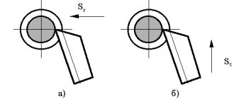
Let's consider the option when, when checking the laser level, a failure of only one vertical or horizontal line is detected. In this case, you should not touch the general compensator adjustment screws (green arrow in the photo), as this will not give the desired result.
Of course, you can use them to level the vertical, but then the horizon will be lost.
This requires adjustment of a specific module with an emitter; in the ADA 2D Basic Level it is secured with three small hexagon socket bolts, so small keys will be needed for repairs.
To begin with, we release the red bolt, since it secures the module in the pendulum socket, then with two yellow bolts we adjust the position of the emitter depending on the projection of the plane relative to the desired one.
When we have found the desired position, fix it with a red bolt and clamp the yellow ones.
ATTENTION! You need to twist the yellow pins VERY carefully and over a tiny distance, since any minimal movement immediately affects the error!
Self-adjustment
You can perform the simplest procedure for checking and adjusting a laser level yourself using the 180 degree method. Marking along the beam path is carried out in a certain way at different positions of the level: normal and rotated 180°. If the edges of the beam and the markings made coincide, then there is nothing to worry about - the device is in perfect working order. Otherwise, it will need to be adjusted.
All that can be done in terms of independent settings is:
- by rotating the screw, shift the center of gravity of the level;
- adjust the frontal and lateral roll of the planes with the platform screws;
- Using a plumb line and adjusting the screw, achieve the ideal position of the pendulum.
Other, more precise settings can only be performed by qualified specialists from specialized companies.
Checking the horizontal sighting axis.
When the bubble is positioned in the center of the ampoule, the guidance (sight) line should be horizontal.
To check this condition, select two points (A and B) at a distance of 40-50 meters from each other and vertically install leveling rods on them. Fix the device on a tripod in the middle between the slats, bring the device into working position, take readings on slats A and B. Calculate the excess between points A and B ∆h=a1-b1 (Fig.5)
Rice. 5
Move the device and install it at a distance of 1-2 m from rail A (Fig. 6). Level the device and take readings a2 and b2 along rods A and B, respectively.
Rice. 6
If | (a2-b2)-(a1-b1) | ≤ 3mm, no further adjustment required. Otherwise, do the following: aim the instrument at staff B and remove the eyepiece protective cover. Using an adjustment pin or key, rotate the adjustment screw until the reading b3 is equal to b3= a2-∆h . Repeat all the above steps until | (a2-b2)-(a1-b1) | ≤ 3mm
What is a GNSS receiver (you can see the range here )
What is a tacheometer (you can see the range here )
What is a level (you can see the range here )
What is a theodolite (you can see the range here )
What is a thermal imager (you can see the range here )
What is a locator (you can see the range here )
By whom and how is the adjustment carried out?
If careful reading of the instructions and attempts to independently configure the device did not lead to the desired results, you should contact specialized metrological service centers that have certificates and licenses to perform metrological procedures such as verification and adjustment.
Licenses and state-issued certificates of admission to a certain type of work in geodetic activities confirm the quality of the work performed and services provided, as well as compliance with the requirements and state standards of the material base used and the qualifications of specialists required to carry out the work.
Upon completion of the work, a standard certificate is issued on the results of verification and adjustment of the level.
We're shooting
In order to mark holes in opposite walls on the same line, but at different heights, in a small room, you can use a ruler or tape measure. If the walls are tens of meters apart from each other, this method will be difficult. To solve such problems, most models are equipped with a so-called sighting target. This is a plastic plate with markings reminiscent of the pattern on targets for bullet shooting; the circles are spaced from each other at a certain distance, most often a centimeter or an inch. The vertical and horizontal axes that form the crosshairs of the sight are graduated in millimeters (or lines and dots). The plate has a hole for mounting on a vertical surface. With its help, you can mark the mixture by several centimeters without using the services of a helper.
Laser level with sighting target
The most advanced models are equipped with a sighting device for this purpose, which saves time on hanging the target.
Adjustment result
The result of adjusting device characteristics may not always be positive. If the device at any stage of the settings does not give the desired results or it is impossible to achieve them for various reasons, the level is considered unusable and is taken out of service with a corresponding mark in the technical passport.
The cost of adjustment, as a rule, ranges from 800-1000 rubles. and higher, but the work is usually carried out as a complex, since high-quality adjustment cannot be performed without checking the device.
Checking the device for correct installation
Much depends on the accuracy of the measurement results carried out by the device. If the plane for laying tiles is knocked off, then the evenness of the installation of the tool will affect the interior design. If the plane is checked during the construction of a house, then the installation of the level will affect the quality of construction and the reliability of this structure.
Each device (depending on the model and its cost) has corresponding error indicators
The permissible error values are indicated directly in the instructions for the equipment, which should be taken into account when purchasing a tool. Acceptable error values are indicated in the appropriate units of measurement, which are mm/m
Errors are not so important when using the device indoors, but they are extremely necessary when carrying out external work on beating a plane and leveling walls.
The error is one of the main technical parameters of the instrument, and some manufacturers indicate the magnitude of deviations not only in the technical documentation, but also on the body of the device. If the magnitude of the error is known, then the permissible deviation from the norm can be calculated. If the deviation value is higher than permissible, it is recommended to use a level with a smaller error value.
It doesn't matter if the laser level is being used to level a floor, wall or ceiling, but before taking the corresponding measurements, you will need to check the accuracy. The check is quite simple, for which the following steps are performed:
- First you need to put marks on two parallel walls in the room, according to which the check will be carried out
- One mark is placed on the wall that is closer to the device (at a distance of up to 1 meter)
- The second mark is placed on the opposite wall, located at a distance of more than 2 meters. The further the distance between the walls, the more accurately device deviations can be identified
- After marking with a marker or pencil on the wall, you need to move the level directly to the wall, which was further from the level
- Align the directional laser beam with the point that was marked. Then project the beam onto the opposite side and see if it matches the mark
- If it matches, then the instrument has an insignificant error (note that the greater the distance between the walls, the higher the error, and the smaller the gap between them, the correspondingly lower the error)
- If the laser beam does not coincide with the mark, then there is an error, and its magnitude is quite high. There are special adjustment screws in the device body, which also allow you to adjust the level, reducing deviations from the norm
Before using a laser level to level walls, you need to make sure that there are no large deviations, otherwise the indicators will not correspond to reality. Below is a video instruction and training on how to properly check the level for measurement accuracy.
https://youtube.com/watch?v=ffrWqniqrfs%3F