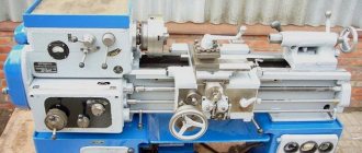
The cam lathe chuck is a necessary component for a lathe. The final result of the work depends on the quality of the clamping device. In particular, if the chuck does not provide the greatest clamping force, the part may simply fly off the front end of the spindle. The device is responsible for the accuracy of centering and influences whether the processing axis will be exactly perpendicular to it. Of course, the issue of choosing a component should be taken very seriously, since it determines the effectiveness of the procedure and the quality of the resulting parts.
Main design options
Lathe chucks are made of durable cast iron with a grade of at least SCh-30 or tool steel grades with a strength of at least 500 MPa.
There are various design options for lathe chucks; we will focus on the most commonly used in modern production:
Lever chuck. The clamping occurs due to the displacement of the cams with clamps due to the action of a two-arm lever. The main characteristic is the number of cams and the degree of displacement on the working disk. The disadvantages include the difficulty of setting up, especially when carrying out non-standard operations. The cams can be adjusted by moving them simultaneously using a key or by individually adjusting each clamp. This type of equipment is usually used for roughing or semi-finishing.
Wedge lathe chucks are an improved version of the lever clamp design. High accuracy of fixation is ensured by the presence of its own mechanical or pneumatic drive for each cam. It has the ability to fix the workpiece with an offset relative to the center of rotation, which makes it possible to process parts of complex configurations.
Diaphragm lathe chucks. Provide the highest fixation accuracy thanks to membranes made of elastic material. The workpiece is fixed by turning off the hydraulic drive, which leads to expansion of the membrane. Characteristic features of the design are a large number of clamps with a relatively low compression force. Therefore, the main area of application of this type of equipment is finishing of parts at low rotation speeds.
By type of execution
In the Russian Federation, the types of cartridges by design are regulated by GOST 2675 - 80.
Whole
Made from a piece of steel with parameters starting from 500 MPa. The most common type.
Made
A rail is made of steel, and a cam is attached to it. The latter is made of metal.
Overhead
Composite variations consist of non-ferrous metal, stainless steel, ferrous metals. Used for working with large-scale projects.
Thermal cartridge
Thermal chuck is used for the same purposes as a collet chuck. The difference lies in the principle of clamping the tool: a shrink fit is used for this in the thermo-chuck. The cartridge is heated in a special device, and its hole increases due to thermal expansion. Then the tool is inserted into it, and the cartridge is cooled (in air or in a special device). Unclamping occurs in a similar way.
The advantage of a thermal chuck is its high clamping force, which cannot be achieved in a collet chuck, much less a drill chuck. The use of such a chuck reduces vibration and significantly increases the durability of the tool.
Disadvantages: tools of different diameters require different chucks; constant cycles of heating and cooling lead to severe wear of the cartridge; Special equipment is required to change tools.
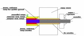
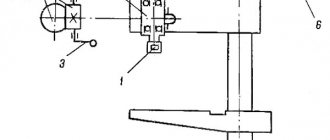
Principle of operation
The chuck of a wood cutting machine is used in closed environments where there are no aggressive substances that cause corrosion. Before starting work, tighten the coupling bolts to the maximum using a wrench. After this, the lathe chuck is mounted on the machine, all the bolts are tightened with nuts and the lathe unit is started. You should first set the speed to low to check the values of the axial and radial runout of the device at idle. In order to secure the workpiece on machines, two-jaw and three-jaw chucks are used, rarely four-jaw chucks. The lathe part for fixing and holding parts is equipped with cams, their number is 2-6 pieces.
In this case, the products can be with independent movement of the cams and with their fastening to the flanged end of the spindle. Depending on the method of fixing the lathe chuck to the machine, the following types of fastening are classified:
- using an adapter flange,
- to the flanged end of the spindle,
- onto the lathe spindle itself.
By simultaneously moving the clamping jaws in the radial direction, centering of the workpiece in the chucks is achieved. The cams move thanks to a disk, which on one side is equipped with grooves in the form of an Archimedean spiral, and on the other there is a bevel gear that interacts with three others. Using the key, one wheel begins to move, and at the same time the disk rotates, moving all the cams evenly. The direction of rotation of the disk determines whether the jaws approach the center of the chuck, while the workpiece is clamped, or move away from it (release of the part).
In mechanical chucks, the clamping force depends on a hydraulic or pneumatic cylinder located at the rear end of the spindle. The cylinder is connected by means of a rod to the chuck mechanism, which moves the cams that clamp the workpiece through the spindle hole in its central part.
During the processing process, compressed air or liquid enters the rotating cylinder using a special device called a coupling. Typically, the movement of the cams from the drive, which is mechanized, approaches a value of 5-10 mm. Because of this, the design of the lathe element allows you to quickly reinstall the product during the transition between batches of workpieces in the processing process.
During finishing processing on a machine, in order to secure the workpiece extremely precisely, overhead non-hardened jaws are used, which are sharpened on the machine to the required dimensions of the workpiece mounting bases. To do this, the main jaws are used as a short mandrel clamp to select clearances in all interactions, then the operating surfaces of the overhead jaw are bored to a larger diameter of the base surface of the part.
Thanks to the dovetail coupling, the design of the non-hardened jaws and their fixation allows the installation of overhead jaws with an accuracy of 002 mm and bypasses their subsequent boring.
To quickly change workpiece sizes, non-hardened cams are needed. This can be achieved by turning the round or hexagonal shaped heads of the overhead cams, mounted on the main cams and bored to a certain diameter, into the desired position.
If there is a need to process two identical surfaces on a machine, then non-hardened cams are used; if the error in fastening the workpieces in them can be reduced to 0.03 -0.05 mm. Workpieces with longer lengths such as shafts are installed in a lathe chuck that has a rear center clamp.
Specifications.
The chuck body is made of high quality special cast iron
Fig. 1 - General view and main dimensions of a three-jaw lathe chuck.
Technical characteristics of the lathe chuck are given in Table 1
Table 1
| Name of parameters | Values |
| Outer diameter D, mm | 250 |
| Diameter of connecting belt D2, mm | 200H7 |
| Diameter of hole in housing D1, mm | 76 |
| Diameter of mounting holes, mm, D3 | 224 |
| Outer diameter of the product clamped in straight jaws, largest mm | 120 |
| Outer diameter of the product clamped in the return jaws, largest mm | 266 |
| Maximum permissible rotation speed, min ' | 2000 |
| Flange side height | 5 |
| Chuck height without jaws | 85 |
| Height of chuck assembly | 119 |
| Cartridge weight, kg | 29 |
| Fasteners | 6 M12 bolts |
Using a lathe chuck, using straight and reverse jaws, you can clamp workpieces in the following range of sizes
The straight cam is designed to secure the workpiece to the outer surface of the shaft or to the inner surface of the hole in the workpiece. The reverse cam is designed to secure the workpiece to the outer surface.
Accuracy characteristics of lathe chuck
Fig.2.1 - Lathe chuck at idle speed
the cartridge provides the following accuracy characteristics: Radial runout a – 0.045 mm;
End runout c – 0.025mm.
By securing the workpiece in the chuck, the following characteristics can be achieved:
Scheme I:
Rice. 2.2 - Lathe chuck with straight jaws attached to the outer surface of the workpiece.
range of fixed workpieces from 5 to 118mm;
Radial runout a at a length of 80 mm is 0.040 mm.
Scheme II:
Rice. 2.3 - Lathe chuck with workpiece fastened to the outer surface with reverse cams.
range of fixed workpieces from 77 to 188 mm and from 160 to 250 mm;
Radial runout a – 0.045mm;
End runout c – 0.025mm.
Scheme III:
Rice. 2.4 - Lathe chuck with workpiece fastened to the inner surface with straight jaws.
range of fixed workpieces from 62 to 174 mm and from 145 to 256 mm;
Radial runout a – 0.045mm;
End runout c – 0.025mm.
Intermediate flanges for self-centering chucks
Before use, the lathe chuck must be installed and secured at the front end of the spindle, but given the difference in the design and size of the seats of lathe chucks and spindles, it is not always possible to secure the chuck directly to the front end of the spindle, for example:
- If the chuck has a centering belt (ledge), then an intermediate (adapter) flange is required to install it on the spindle, regardless of the type of spindle end
- If the chuck has a centering cone, but the size of the cone does not match the size of the centering cone of the spindle end, an intermediate (adapter) flange is also required
- If the end of the spindle ends with a thread, then an intermediate (adapter) flange is required to install any chuck on it
GOST 3889-80 (DIN 6350) Intermediate flanges for self-centering chucks
This standard applies to intermediate flanges intended for installation on the ends of spindles of metal-cutting machines with self-centering general purpose chucks.
Intermediate flanges (they are also called plan washers) are necessary for centering and fastening chucks with a centering belt (GOST 2675 type 1) on any of the 4 types of lathe spindle ends.
GOST 3889-80 Flanges must be manufactured in the following versions:
- Version 1 – installed on the threaded ends of spindles in accordance with GOST 16868;
- Version 2 – installed on the flanged ends of spindles in accordance with GOST 12593 under a rotary washer;
- Version 3 – installed on the flanged ends of spindles in accordance with GOST 12595 version 1;
- Version 4 – installed on the flanged ends of spindles in accordance with GOST 12595 version 3.
GOST 3889 Version 1. Intermediate flanges for threaded ends of spindles
GOST 3889 Intermediate flanges for threaded ends of spindles
In order to secure a lathe chuck at the front end of the spindle, it is necessary to make or purchase an intermediate (adapter) flange, which is also called a faceplate.
From the spindle side, the intermediate flange must be screwed onto the spindle thread d and very accurately slide onto the centering belt - a cylinder with a diameter of Ø d1 and a length of l mm.
On the side of the lathe chuck, the intermediate flange must have a centering belt - step D4 for precise installation and centering of the lathe chuck on the intermediate flange, and also have through holes for attaching the chuck. Obviously, for each standard size of lathe chuck there must be its own intermediate flange.
It is allowed to install 1 locking device against self-unscrewing on the intermediate flange of the design.
The lathe chuck installation process consists of the following steps:
- The intermediate flange is screwed onto the spindle thread until it stops. The hole in the flange should fit tightly onto the spindle collar
- The screws of the locking device are tightened against self-unscrewing
- Check the runout of the centering belt on the flange (D1) and the supporting end surface on the chuck side
- A cartridge is installed on the centering belt (D1) and secured with bolts
- The radial and axial runout of the chuck is checked
Example: intermediate flange for a TV-4 lathe
Intermediate flange for TV-4 lathe
An example of a designation for a flange of version 1, with a diameter of 100 mm:
Flange 7081-0592 GOST 3889-80
An example of a designation for a flange of version 1, with a diameter of 125 mm:
Flange 7081-0593 GOST 3889-80
Intermediate flange for a lathe with a threaded spindle end
GOST 3889-80 Intermediate flanges for rotary washer
GOST 3889-80 Intermediate flanges to the ends of spindles type A. Version 1
Drive cartridges with a sunken center
Drive chucks with a sunken center are designed for fastening parts on the outer untreated surface with simultaneous centering with a supplied center 1 . The pressure of the part insulates the center and ensures that its end reaches the base surface of the nut 2 .
The center is locked when clamped automatically by cams 5 , which impart rotation to the nuts 4 and sliders 5 (relative to the axis of the chuck). Thanks to the inclined grooves, the sliders are imparted translational movement along the axis of the grooves. In this case, the crackers move along inclined grooves and push the cams all the way to the nut 2 .
| D | clamp d | H | |
| max | min | ||
| 170 | 50 | 10 | 70 |
| 220 | 70 | 20 | 90 |
Related Pages
- Diaphragm cartridges and mandrels
- Solid conical mandrels
- Mandrels and plugs for installation and fastening of workpieces on the external machined surface
- Mandrels and plugs for installation and fastening of workpieces on the internal machined surface
- Mandrels and plugs for installation and fastening of workpieces on the internal untreated surface
- Mandrels and chucks for fastening workpieces on a threaded surface
- Rotating centers
- Machine vice
- Machine tables
- Machine stands
- Dividing devices for machine tools
- Conductors and stands for overhead conductors
- Gripping devices for automatic lines
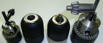
Drill chuck. How to choose ?
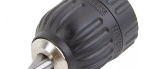
Self-clamping chuck
Such chucks (sometimes called quick-release chucks) also sometimes have conical elements in their design, but mostly use internal threads (this is indicated on the product labeling).
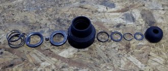
Self-clamping chuck includes:
- A bushing with an axial hole in the form of a cone.
- Clamping ring equipped with corrugations.
- Frame.
- A couple of jamming clamping balls.
The principle of operation of a self-clamping chuck is that the drill clamp is provided and maintained during the rotation of the spindle itself, which is especially useful in conditions of frequent use of the drilling machine. A drill with a conical shank of the same number is inserted into the sleeve, and it is inserted into the hole in the body. As a result, the clamping ring is raised and the clamping balls fit into the holes on the outer surface of the replacement sleeve. When lowering the ring element, the balls are placed in the holes and provide clamping of the device.
In this case, replacing the drill can be done without turning off the machine. The operator only lifts the ring, the balls move apart and release the replaceable sleeve, which is then removed from the device. Subsequently, a new replacement bushing can be installed in its place, for which the same manipulations are performed. Typically the kit comes with several split bushings having different Morse taper numbers. You can insert several parts one into one, thereby increasing the number of possible combinations.
The keyless chuck can also have a different design, used when the part already has a hole, and it is necessary to center the drill (countersink, reamer) relative to its axis. The device has a movable mandrel and a driver, which is located in a non-circular hole in the inner part of the body. The bearing assembly compensates for possible axial forces. The coupling is screwed to the mandrel, connecting it to the body, and is secured from below with a retaining ring. The spring, which is located inside the mandrel, presses it against the body. This ensures precise positioning of the chuck according to the depth of the existing hole. The chuck is removed from the spindle using either wedges (flat or radius) or an eccentric wrench.
Three jaw drill chuck
Three cams are placed in the housing at an angle that prevents self-braking of the elements. When the key, which is inserted into the corresponding hole on the body, rotates, the cage and nut begin to move. As a result, the cams are retracted, and simultaneously in the radial and axial directions. Along the axis of the chuck, a space is formed where the tool shank is placed. When the shank rests on the thrust bearing, the key is turned in the opposite direction and the cams are brought into tight contact with the conical part of the shank. At the same time, the axial orientation of the tool relative to the spindle is also carried out.
Due to the simplicity of the design and the method of adjusting the tool, three-jaw chucks are primarily used in small workshops, as well as in household drilling machines.
The disadvantage of three-jaw chucks is noticeable wear of the jaws, especially if they are heat treated to insufficient hardness.
In addition to the designs described, other types of cartridges are also used. For example, collet chucks are used to install relatively small diameter drills. In them, fixation is carried out by pressing the split sleeve, where the drill is located, with a union nut. It moves along the threads that are on the body of such a cartridge and reliably presses the sleeve against the collar of the cylindrical part of the body. Collet chucks, unlike jaw chucks, are much easier to disassemble, which facilitates the process of cleaning and repairing them.
For precision and high-speed drilling machines, chucks with a hollow shank are most effective. The upper part of such a shank is threaded, and in the lower part there is a hole into which coolant is supplied under pressure of up to 50 atmospheres. Drill chucks of the HEHA series allow coolant to be supplied through radially or coaxially located holes in the body. A peculiarity of the use of such equipment is the need for its dynamic balancing, which takes into account both the torques from the drilling machine drive and the pressure created by the coolant flow.
Device and principle of operation.
3.1. The design of a spiral rack lathe chuck is shown in Fig. 3.
Fig. 3 - Design of a spiral rack lathe chuck.
Cams 1, 2 and 3 of the cartridge move simultaneously using disk 4. On one side of this disk there are grooves (shaped like an Archimedean spiral) in which the lower projections of the cams are located, and on the other there is a cut bevel gear mated to three bevel gears 5. When you turn one of the wheels 5 with a key, disk 4 (thanks to gearing) also turns and, by means of a spiral, simultaneously and evenly moves all three cams along the grooves of the cartridge body 6. Depending on the direction of rotation of the disk, the cams move closer to the center of the chuck or move away from it, clamping or releasing the part. The cams are made in three stages and are hardened to increase wear resistance.
Double-jaw chuck for installing parts such as tees
The installation prism 1 and the clamping cam 2 are replaceable, this allows you to install parts with pipes with a diameter of up to 50 mm. Rotation through angles of 90° and 180° is carried out together with bracket 3 . The position of the bracket is fixed with finger 4 when turning the locking axis 5 .
Collet chucks
A collet chuck is a special device used for clamping a tool when performing turning, milling, drilling and other operations related to the processing of metal workpieces based on the technical specifications (sequence of operations, processing technology, attached sketch of the product).
Collets
Types and principles of operation of chucks
Collet chucks are used mainly when processing cold-rolled rods or other metal products that have an already machined surface.
Structurally, cartridges can be classified according to functionality:
- with a fixed mechanism;
- with retractable mechanism;
- with retractable mechanism.
Each design has its own characteristics. The feeding type is made in the form of a steel sleeve with 3 cuts forming petals that have a springing effect.
Type F
Collets type F - clamping the main spindle are used to secure the workpiece.
Type LN
Collets type LN - counter spindle are produced elongated, size E depends on the standard size.
Type R
Type R – are pull-type collets.
Drawing No. 5 collet BF
Type BF
BF type feed collet - designed for bar feeding.
When installed on the machine, the feed collet is threaded onto the pipe with the help of which it is fed into the working area. It is necessary to take into account the design feature - the size and shape of the collet, which must necessarily correspond to the profile of the bar being processed.
In preparation for processing, the rod moves through the petals, which, due to their design features, tightly hold the workpiece. During processing, when feeding the workpiece, the adhesion force between the petals and the product increases due to rotation.
Jaws for two- and three-jaw mechanized wedge lathe chucks
| Chuck model | Main cam | Top jaws | |
| unhardened | tempered | ||
| Diameter 200 | |||
| 7102-0021M-1-2 | 7102-0071U-1-2/002M | 7102-0071U-1-2/005M | 7102-0071U-1-2/003M |
| 7102-0070M-1-2 | |||
| 7102-0071M-1-2 | |||
| 7102-0075M-1-2 | |||
| Diameter 250 | |||
| 7102-0027M-1-2 | 7102-0073У-1-2/004М | 7102-0073У-1-2/007М | PKV-250⌀8.95/006M |
| 7102-0072M-1-2 | |||
| 7102-0073M-1-2 | |||
| 7102-0076M-1-2 | |||
| 7102-0077M-1-2 | |||
| 7102-0078M-1-2 | |||
| Diameter 315 | |||
| 7102-0080M-1-2 | 7102-0080U-1-2/002M | 7102-0088U-1-2/007M | PKV-400⌀11.93/006M |
| 7102-0081M-1-2 | |||
| Diameter 400 | |||
| 7102-0085M-1-2 | 7102-0088U-1-2/004M | 7102-0088U-1-2/007M | PKV-400⌀11.93/006M |
| 7102-0086M-1-2 | |||
| 7102-0087M-1-2 | |||
| 7102-0088M-1-2 | |||
| Diameter 500 | |||
| 7102-0092M-1-2 | 7102-0092U-1-2/004M | 7102-0088U-1-2/007M | PKV-400⌀11.93/006M |
| 7102-0093M-1-2 |
Workpiece processing scheme
Figure No. 1. Scheme of part processing. Designation of device elements: 1 - drive cartridge; 2 – fastening leash-clamp; 3 – fixing bolt; 4 – movable steady rest; 5 – product being processed.
Lathe driver chucks used in turning work are made in the form of a disk with four grooves and a threaded bushing having identical dimensions to the headstock spindle. When using a straight clamp, a movable pin is installed in the cartridge, fixed with a nut in the groove of the fastener. When processing the workpiece, the pin rests against the tail of the clamp. The cartridges used must comply with GOST 2571-71, GOST 13364-67, GOST 1435-99 and GOST 25557-2006 for all established parameters.
Download GOST 2571-71 “Drive-type lathe chucks”
If a curved clamp is used during a turning operation using a lathe, the pin is not used, since the tail of the clamp is installed in the groove of the locking element.
Drawing No. 2. Drive chuck design. Designation: the main elements that make up the fastening element of the workpiece being processed.
This design has protruding parts, which allows the possibility of injury to the specialist processing the product. To eliminate the possibility of injury, a closed cartridge is used, made in the form of a casing with a boss and a threaded sleeve identical to the open element. The clamp is hidden inside the casing, which ensures safe work.
Drawing No. 3. The design of the driving chuck, made with a closed body. Designation of elements: 1 - cap with tide; 2 – outer sleeve; 3 – clamp.
Fastening elements that do not provide for the use of a clamp are also used. In order to speed up the processing of products, instead of clamps, front centers are used, which simultaneously perform two operations: centering the workpiece and acting as a leader (Drawing No. 4). When the product is exposed to the rear center, the corrugated notches are pressed more tightly to the sides of the part and impart a rotational movement to it. When turning hollow products, external grooved centers are used, and when using rollers, internal grooved centers are used.
Drawing No. 4. Fixing the workpiece using a driving chuck. Designation: 1,2 – centers.
The workpiece to be processed is supported on the center, and the cams are used to transmit rotation to the workpiece. Moreover, the cams are made floating for more complete fixation of the part. The mandrel is fixed using the clamping force acting between the tailstock and the front center of the lathe mechanism, which moves to the left, as a result of which the cams take the optimal position and fix the workpiece more tightly. The conical support ring has a gap, which allows it to occupy a middle position due to springs. Rotational movements of the workpiece are ensured by cams with a grooved surface.
Safe and dangerous leash cartridges
Re-adjustable universal chucks for fastening workpieces on a flange surface
Designed for fastening workpieces with pressure to the end surface. To install various workpieces, the chucks are equipped with replaceable adjustment devices 1 , which are centered along the hole.
The clamping elements are two cams 2 , mounted on a swinging cross-beam 3 , connected to the pneumatic drive with bolts 4 . The cams are adjusted to a given size by moving them radially. The rotation of the cams occurs automatically using guide bayonet grooves. The chuck drive is pneumatic.
Dimensions in mm
| H | D ( add. off according to A) | D1 | D2 | D3 | h | d | d1 | ||
| min | max | min | max | ||||||
| 65 | 145 | 50 | 250 | 125 | 68 | 15 | 38 | M16 | M8 |
| 80 | 190 | 320 | 175 | 70 | 24 | 46 | M10 | ||
GOST 2675-80 SELF-CENTERING THREE-JAW CHUCKS
1. The standard applies to self-centering spiral-rack three-jaw chucks of accuracy classes N, P, V, A, installed on machine spindles through adapter flanges and directly on the flanged ends of the spindles.
2.Cartridges must be made of the following types:
Type 1 - with a cylindrical, centering belt and with fastening through an intermediate flange in accordance with GOST 3889-80.
Type 2 - with fastening directly to the flanged ends of the spindles under a rotary washer in accordance with GOST 12593-72;
Type 3 - with fastening directly to the flanged ends of spindles in accordance with GOST 12595-85.
1, 2. (Changed edition, amendment No. 1).
3. Cartridges of all types are manufactured in the following versions:
- with solid cams,
- with assembled cams.
4. The main dimensions of cartridges of types 1, 2, 3 must correspond to those indicated in drawing 1 and table 1.
An example of a symbol for a type 1 chuck, 200 mm in diameter with solid jaws, accuracy class H:
Cartridge 7100-0007 GOST 2675-80
The same, type 2 chuck with a diameter of 200 mm, mounted on a spindle with nominal size 5, with prefabricated jaws, accuracy class P:
Cartridge 7100-0032-P GOST 2675-80
Purpose.
The self-centering three-jaw lathe chuck belongs to the class of spiral-rack self-centering three-jaw chucks with a cylindrical belt and mounting on a lathe through an intermediate flange.
Self-centering spiral rack lathe chucks are designed for installation on universal lathes, turrets, and internal grinding machines. They are used in conditions of single, small-scale and mass production. Three-jaw self-centering chucks hold round and hexagonal workpieces or round rods of large diameter. Unlike wedge-type lathe chucks, they do not require time for readjustment in the case when installation to a different clamping diameter is required.
Operating principle and features
The cartridge is placed in a universal or highly specialized machine. It is needed for mounting elements on the spindle axis. They provide a reliable grip on the workpiece, and at the same time improve clamping at high speeds.
Operate in a clean, dry place, all chemical liquids that cause corrosion are removed to preserve the cartridge. Then, before work, all the coupling bolts are tightened all the way with a wrench. The next step is to fasten the cartridge element into the turning unit, tighten the bolts with nuts and turn on the machine.
It is best to start the unit at low speeds in order to check the strength of the assembly and at the same time calibrate the values of the axial and radial runout at idle.
In order to secure the workpiece on the machine, a chuck with two or three jaws is most often used. At the same time, there are parts with independent movement of the cams.
These same teeth move together in a radial direction, due to which the workpiece is held in the processing zone.
The cams move through a disk, which on one part has “Archimedean spiral” grooves, and on the other side there is a bevel gear that interacts with the other wheels.
The first wheel begins to move through the key, and at the same time the disk begins to work, which simultaneously moves the cams. If they move closer to the middle of the cartridge, then the workpiece is compressed, but if, on the contrary, they move away, then the workpiece is released.
Self-assembly of the cartridge according to the drawings
Self-assembly does not take much time. This is a fairly simple process. The main thing is to understand the mechanism of operation of the device. As a last resort, you can order such miniature equipment from a professional turner. He will assemble any variation from the available parts. Homemade models cost significantly less than those ordered from production.
The quality may be even better than factory ones.
Installation of the mandrel
The frame is put on first. Installing the part makes it possible to secure the cartridge.
Installing the chuck itself on the spindle
The mechanism is being secured. Do not press or bore parts. At this stage, fastening occurs with previously prepared bolts of suitable size.
Consolidation
After checking the quality of the wrapping, the final assembly of the mechanism is carried out. The bolts are screwed using a wrench.
Securing the workpiece
Tools are installed on a homemade cartridge. Carried out after checking the assembly with bolts.
Releasing the cartridge
Once the workpiece is screwed in, the frame is no longer needed. It is carefully removed.
It is imperative to check the functionality of the self-made mechanism. The product is placed in a lathe. Several smooth turns are made and the clarity of the fastening is checked. The specialist assesses the level of centralization and whether objects move.
Homemade cartridges must be periodically serviced. They are completely disassembled, the inside is cleaned, and then dried in the fresh air. Lubricated with regular oil. If the product is going to be stored, then this must be done according to the rules. Bend the fists into the central part, plug the hole tightly with a rag.
Such storage will ensure the integrity of the cartridge, since it cannot be damaged mechanically, and dust will not settle in the hole in the equipment structure. Before use, the old cartridge is lubricated and runs for up to 10 minutes at a smooth, slow speed.
Clamping mechanism design
Another important classification of devices, affecting their design and application, concerns the assembly of the clamping mechanism. According to this parameter, chucks for lathes are divided into the following types:
- Drivers are the simplest, used for processing the center; if it is necessary to sharpen the side surfaces, gear and pin units are selected;
- Spiral self-centering - centering occurs simultaneously with fixation, which reduces the time required for preparation. The most popular lathe chucks are equipped with two, three or six holders;
- Lever - their feature is the presence of a rod with a coupling, driven by a hydraulic drive. Due to this, fastening occurs. In demand in small-scale production;
- Wedge rack - this lathe chuck is similar in characteristics to a lever chuck, but provides greater centering accuracy;
- Collet - capable of fixing only rod samples with a small diameter. Despite the low versatility, they are popular due to minimal radial runout, which improves the quality of work;
- Drilling - designed for connecting drills and other tools to the machine;
- Thermal chucks - used on the same machines as collet chucks, but they require a shrink fit to connect the tool;
- Hydraulic chucks are another alternative to collet devices. The lathe chuck clamps the tool due to the operating fluid pressure, which reduces the force required for reliable clamping.