10.7.
The vertical maximum deflections of structural elements and the loads from which the deflections should be determined are given in Table. 19. Requirements for gaps between adjacent elements are given in paragraph 6 of recommended Appendix 6.
Vertical limit deflections fu
Loads for determining vertical deflections
1. Crane track beams for overhead and overhead cranes, controlled by:
from the floor, including hoists (hoists)
From one tap
from the cabin with groups of operating modes (according to GOST 25546-82):
Physiological and technological
2. Beams, trusses, crossbars, purlins, slabs, decking (including transverse ribs of slabs and decking):
a) coverings and ceilings open to view during the flight l
Permanent and temporary long-term
b) coverings and ceilings with partitions underneath them
Accepted in accordance with paragraph 6 of recommended Appendix 6
Leading to a reduction in the gap between load-bearing structural elements and partitions located under the elements
c) coatings and ceilings if they contain elements susceptible to cracking (screeds, floors, partitions)
Effective after the completion of partitions, floors, screeds
d) coverings and ceilings in the presence of hoists (hoists), suspended cranes controlled by:
/300 or a
/150 (lesser of the two)
Temporary, taking into account the load from one crane or hoist (hoist) on one track
/400 or a
/200 (the lesser of the two)
From one crane or hoist (hoist) on one path
e) floors exposed to:
Physiological and technological
transported cargo, materials, units and elements of equipment and other moving loads (including trackless floor transport)
0.7 full standard values of live loads or loads from one loader (the more unfavorable of the two)
loads from rail transport:
From one train of cars (or one floor machine) on one track
3. Elements of stairs (flights, platforms, stringers), balconies, loggias
The same as in pos. 2, a
Determined in accordance with clause 10.10
4. Floor slabs, flights of stairs and landings, the deflection of which is not hampered by adjacent elements
Concentrated load 1 kN (100 kgf) in the middle of the span
5. Lintels and curtain wall panels over window and door openings (crossbars and glazing purlins)
Leading to a decrease in the gap between the load-bearing elements and the window or door filling located under the elements
The same as in pos. 2, a
Designations adopted in table. 19:
design span of a structural element;
— the pitch of beams or trusses to which suspended crane tracks are attached.
Notes: 1. For console instead of l
its offset should be assumed to be double.
2. For intermediate values of l
in pos. 2, a
maximum deflections should be determined by linear interpolation, taking into account the requirements of paragraph 7 of recommended appendix b.
3. In pos. 2, a
The figures indicated in brackets should be taken for room heights up to 6 m inclusive.
4. Features of calculating deflections by position. 2, g
are indicated in paragraph 8 of recommended Appendix 6.
5. If deflections are limited by aesthetic and psychological requirements, a span of l
taken equal to the distance between the internal surfaces of load-bearing walls (or columns).
The distance (gap) from the top point of the overhead crane trolley to the bottom point of the bent load-bearing structures of the coverings (or objects attached to them) must be at least 100 mm.
The deflections of the covering elements must be such that, despite their presence, a roof slope of at least 1/200 in one of the directions is ensured (except for cases specified in other regulatory documents).
The maximum deflections of roof elements (beams, crossbars, slabs), stairs, balconies, loggias, premises of residential and public buildings, as well as household premises of industrial buildings based on physiological requirements should be determined by the formula
- acceleration of gravity;
normative value of the load from people exciting vibrations, taken according to table. 20;
1 —
reduced standard value of load on floors, taken according to table. 3 and 20;
standard value of the load from the weight of the calculated element and the structures resting on it;
frequency of application of load when a person walks, taken according to table. 20;
— coefficient accepted according to the table. 20.
Maximum deflection of a metal beam - Metalworker's Handbook
The beam is the main element of the supporting structure of the structure.
During construction, it is important to calculate the deflection of the beam. In real construction, this element is affected by wind force, loading and vibration. However, when performing calculations, it is customary to take into account only the transverse load or the applied load, which is equivalent to the transverse one. When calculating, the beam is perceived as a rigidly fixed rod, which is installed on two supports. If it is installed on three or more supports, calculating its deflection is more complex, and it is almost impossible to do it yourself.
The main load is calculated as the sum of forces that act in the direction of the perpendicular section of the structure. A design diagram is required to determine the maximum deformation, which should not exceed the limit values.
This will allow you to determine the optimal material of the required size, cross-section, flexibility and other indicators.
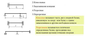
Types of beams
Beams made of strong and durable materials are used for the construction of various structures. Such structures may differ in length, shape and cross-section.
Wooden and metal structures are most often used. For the deflection calculation scheme, the material of the element is of great importance.
The specifics of calculating the deflection of a beam in this case will depend on the homogeneity and structure of its material.
Wooden
For the construction of private houses, cottages and other individual construction, wooden beams are most often used. Wooden structures that work in bending can be used for ceilings and floors.
To calculate the maximum deflection, consider:
- Material. Different types of wood have different strength, hardness and flexibility.
- Cross-sectional shape and other geometric characteristics.
- Various types of load on the material.
The permissible deflection of the beam takes into account the maximum real deflection, as well as possible additional operational loads.
Coniferous wood structures
Steel
Metal beams have a complex or even composite cross-section and are most often made from several types of metal. When calculating such structures, it is necessary to take into account not only their rigidity, but also the strength of the connections.
Metal structures are made by connecting several types of rolled metal, using the following types of connections:
- electric welding;
- rivets;
- bolts, screws and other types of threaded connections.
Steel beams are most often used for multi-story buildings and other types of construction where high structural strength is required. In this case, when using high-quality connections, a uniformly distributed load on the beam is guaranteed.
To calculate the beam for deflection, this video can help:
Beam strength and rigidity
To ensure the strength, durability and safety of the structure, it is necessary to calculate the deflection value of the beams at the design stage of the structure. Therefore, it is extremely important to know the maximum deflection of the beam, the formula of which will help draw a conclusion about the likelihood of using a certain building structure.
Using a calculation scheme of rigidity allows you to determine the maximum changes in the geometry of the part. Calculating a structure using experimental formulas is not always effective.
It is recommended to use additional coefficients to add the necessary safety margin.
Not leaving an additional margin of safety is one of the main construction mistakes, which leads to the impossibility of using the building or even serious consequences.
There are two main methods for calculating strength and stiffness:
- Simple. When using this method, a magnification factor is applied.
- Accurate. This method includes the use of not only safety factors, but also additional calculations of the boundary state.
The last method is the most accurate and reliable, because it helps determine exactly what load the beam can withstand.
Stiffness calculation
To calculate the bending strength of a beam, the formula is used:
Where:
M is the maximum moment that occurs in the beam;
Wn,min – moment of resistance of the section, which is a tabular value or is determined separately for each type of profile.
Ry is the design bending resistance of the steel. Depends on the type of steel.
γc is the operating condition coefficient, which is a tabular value.
Calculating the stiffness or deflection of a beam is quite simple, so even an inexperienced builder can perform the calculations. However, to accurately determine the maximum deflection, you must perform the following steps:
- Drawing up a design diagram of the object.
- Calculation of the dimensions of the beam and its section.
- Calculation of the maximum load that acts on the beam.
- Determination of the point of application of maximum load.
- Additionally, the beam can be tested for strength by maximum bending moment.
- Calculation of the stiffness value or maximum deflection of a beam.
To create a calculation scheme, you will need the following data:
- beam dimensions, length of consoles and span between them;
- cross-sectional size and shape;
- features of the load on the structure and its exact application;
- material and its properties.
If a two-support beam is being calculated, then one support is considered rigid, and the second is considered hinged.
Calculation of moments of inertia and section resistance
To perform stiffness calculations, you will need the moment of inertia of the section (J) and the moment of resistance (W). To calculate the moment of resistance of a section, it is best to use the formula:
An important characteristic when determining the moment of inertia and resistance of a section is the orientation of the section in the cut plane. As the moment of inertia increases, the stiffness index also increases.
Determination of maximum load and deflection
To accurately determine the deflection of a beam, it is best to use this formula:
Where:
q is a uniformly distributed load;
E – elastic modulus, which is a tabular value;
l – length;
I – moment of inertia of the section.
To calculate the maximum load, static and periodic loads must be taken into account. For example, if we are talking about a two-story structure, then the wooden beam will be constantly subject to the load from its weight, equipment, and people.
Features of deflection calculations
Deflection calculations are required for any floors. It is extremely important to accurately calculate this indicator under significant external loads. In this case, it is not necessary to use complex formulas. If you use the appropriate coefficients, the calculations can be reduced to simple schemes:
- A rod that rests on one rigid and one hinged support and carries a concentrated load.
- A rod that rests on a rigid and hinged support and is subject to a distributed load.
- Options for loading a cantilever rod that is rigidly fixed.
- The effect of a complex load on a structure.
Using this method for calculating deflection allows you to ignore the material. Therefore, the calculations are not affected by the values of its main characteristics.
Example of calculating deflection
To understand the process of calculating the stiffness of a beam and its maximum deflection, you can use a simple calculation example. This calculation is carried out for a beam with the following characteristics:
- material of manufacture – wood;
- density is 600 kg/m3;
- length is 4 m;
- the cross-section of the material is 150*200 mm;
- the mass of the covering elements is 60 kg/m²;
- the maximum load of the structure is 249 kg/m;
- the elasticity of the material is 100,000 kgf/m²;
- J is equal to 10 kg*m².
To calculate the maximum permissible load, the weight of the beam, floors and supports is taken into account. It is also recommended to take into account the weight of furniture, appliances, decoration, people and other heavy things, which will also have an impact on the structure. For the calculation you will need the following data:
- weight of one meter of beam;
- weight m2 of floor;
- the distance that is left between the beams;
- temporary load;
- load from partitions on the floor.
To simplify the calculation of this example, you can take the mass of the floor as 60 kg/m², the load on each floor as 250 kg/m², the load on the partitions as 75 kg/m², and the weight of a meter of beam as 18 kg. With a distance between beams of 60 cm, the coefficient k will be equal to 0.6.
If you plug all these values into the formula, you get:
q = (60 + 250 + 75) * 0.6 + 18 = 249 kg/m.
To calculate the bending moment, use the formula f = (5 / 384) * [(qn * L4) / (E * J)] £ [¦].
Substituting the data into it, we get f = (5 / 384) * [(qn * L4) / (E * J)] = (5 / 384) * [(249 * 44) / (100,000 * 10)] = 0 .13020833 * [(249 * 256) / (100,000 * 10)] = 0.13020833 * (6,3744 / 10,000,000) = 0.13020833 * 0.0000063744 = 0.00083 m = 0.83 cm.
This is precisely the indicator of deflection when a maximum load is applied to the beam. These calculations show that when a maximum load is applied to it, it will bend by 0.83 cm. If this indicator is less than 1, then its use at the specified loads is allowed.
The use of such calculations is a universal way to calculate the rigidity of a structure and the amount of their deflection. It is quite easy to calculate these values yourself. It is enough to know the necessary formulas and also calculate the values. Some data needs to be taken in a table.
Computing Basics
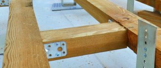
First you need to understand what exactly needs to be calculated. The fact is that a wooden beam or beam board under load can bend to a certain limit - this value is called tensile strength - and break with a further increase in load. Under load, a bent beam may also slip out of its fastenings. To avoid this or at least reduce the risk of such a nuisance, they try to embed wooden beams into the masonry of the house or attach them using brackets, corners and other types of parts to the wooden wall of the house. They also use cutting the beam into the crown of the wall. All such types of fixation are considered rigid fixation.
This is what the design diagram for a single-span beam looks like, that is, a product with only the ends fixed. Here L is the span of the beam, the distance between the support points, Q is the distributed load, f is the deflection value.
The basis for calculating the maximum permissible deflection, as well as the source of other data on the operation of wooden structures, is SP 64.13330.2011. According to this document, the maximum deflection of a beam for interfloor floors should not exceed 1/250 of the span length.
That is, for a beam with a length of 6 m, the permissible deflection will be 24 mm. If we take more strict values (for plaster on the ceiling and floor coverings that require a strict plane on the second floor, for example, tiles) - 1/350, the permissible deflection is reduced to 17 mm.
In general, the formula f = L/350 is used for calculations, with the span length indicated in millimeters.
Table 1.1. Permissible deflection of wooden structures.
Accordingly, when calculating a beam’s strength in an online calculator or manually, the section should be reduced only to those deflection limits that are less than the calculated value.
The illustration above shows a design diagram for a distributed load, that is, one that is evenly distributed over the entire beam. Typically, this scheme is used in residential premises. However, when placing heavy furniture or equipment in a room, especially not near the wall (on which the edge of the beam rests), but at some distance from it, it is sometimes wiser to use a calculation scheme for a concentrated load.
This is approximately how a concentrated load is created on the beam.
Table 1.2. Schemes for calculating wooden beams with one concentrated load.
Here and below, E is the elastic modulus of wood E = 100,000 kgf/m2), I is the axial moment of inertia of the beam.
Table 1.3. Schemes for calculating wooden beams with two concentrated loads.
Table 1.4. Calculation of a beam with two-sided rigid pinching under a uniformly distributed load.
Depending on where exactly the loads are applied and in what quantity, a design scheme of the appropriate type is used.
For a beam clamped in the wall at only one end (cantilever fastening), other formulas are used to calculate the strength of a wooden beam. Typically, such calculations are needed when designing canopies on wooden support beams, large roof overhangs, and other similar cases.
Table 1.5. Calculation of a cantilever beam under one concentrated load.
Table 1.6. Calculation of a cantilever beam under one unevenly distributed load.
Table 1.7. Calculation of a cantilever beam under one uniformly distributed load.
The formulas seem cumbersome and complex, but in fact, when calculating wooden floor beams, it is important for the average user to simply imagine the nature of the distribution of forces acting on the beam and understand that in order to meet the strength conditions, it is necessary to choose the correct load application scheme
Checking steel beam deflections
When calculating steel beams according to the IInd GPS (by deflections), it is necessary to create bracing for deflections:
Information from the LIRA SAPR help (HelpExplanations SteelDeflection checks):
The deflection is checked by comparing the actually determined relative deflection (L/f) with the maximum possible deflection for a given structural element.
In this version, the check is performed only for beams based on the composition of load cases in all combinations. Load reliability coefficients (specified during the formation of the DCS in the LIRA-SAPR PC environment) and combination coefficients are taken into account.
Displacements caused by load cases with duration fraction 0 are not used in this calculation.
Deflections are found for each section based on the distribution of MY1, MZ1, QY1, QZ1 along the length of the element. Accordingly, an increase in the number of design sections contributes to a more accurate determination of deflections (especially if concentrated force factors act).
In the local element calculation mode (see the STK-SAPR help system), it is possible to calculate deflections using the bending moment envelope diagrams in reserve. This may be required when design combinations of forces (or loads) are edited and the connection with the results of the calculation on the LIRA-SAPR PC of the main scheme is lost.
Important: It is possible to determine not pure displacements (relative to the local Y and Z axes in an undeformed scheme), but deflection relative to two selected conditionally fixed points - anchorage points (in the case of a console, for example, relative to one point).
Scheme for determining beam deflections with and without bracing
The fragment shown shows the mechanism for determining deflections (they are designated as di and dk) in a structural element with braces applied to the elements.
If bracing is not applied, then the deflection is assumed to be equal to the full distance to the X axis.
Important: If a beam (crossbar) is split along its length by intermediate nodes, then it is necessary to create a structural element for it and create bracing to check deflections as for a structural element (i.e. for the beam as a whole).
In the analysis of steel structures, the effective length factor (for both beams, columns, and trusses) is applied to the length of the finite element (FE), unless a structural element (SEC) is specified.
If a CoE is specified, the effective length factor is applied to the total length of the CoE.
Calculation model of a frame with a solid crossbar and broken into separate elements
According to regulatory documentation, deflection is determined by the action of standard loads. Since in LIRA SAPR all loads are applied to nodes and elements with their design values, when determining deflections, the program determines the standard value of the loads by dividing them by the reliability factor.
You can see what reliability coefficients are accepted, and also enter them manually, if necessary, in the calculation parameters window.
Calculation parameters window called from the window for setting parameters for steel structures
For more information about adjusting safety coefficients for manually calculating deflections, read the article “Coefficients for live loads when checking deflections”
Mosaic of the results of checking the assigned sections for the 2nd limit state
Maximum permissible L/200=6000/200=30mm
Without specifying bracing (based on the absolute movement of beam nodes): ((39.8mm/load safety factor)/30mm))*100%=((39.8/1.1)/30)*100%=120 .6%
With the assignment of bracing (based on the relative movement of the beam nodes minus the movements of the support nodes): ((39.8mm-9.14)/load reliability factor)/30mm))*100%=(((39.8-9 ,14)/1.1)/30)*100%=92.9%
Manual input of the estimated beam length for calculating deflections
In the dialog box for specifying the calculation characteristics of a steel beam, there is a group of parameters Calculation by deflection.
Information from the LIRA SAPR help: Calculation by deflection - data for calculating deflection. The span length of the car is calculated based on the position of the braces. The span length is exact - the span length during calculation is equal to this number.
Let's consider the frame from the previous example, only now we will assign bracing for deflections for all structures, and the design lengths will be set automatically for the first case, and manually for the second.
Calculation model with information about the assigned design lengths of beams
Calculation results for beam deflections
Maximum permissible deflection with a length of 6 m L/200=6000/200=30mm
Maximum permissible deflection with a length of 4 m L/200=4000/200=20mm
Percentage of use by maximum deflection
Beam length 6 m: ((39.8mm-9.14)/load reliability factor)/30mm))*100%=(((39.8-9.14)/1.1)/30) *100%=92.9%
Beam length 4 m: ((39.8mm-9.14)/load reliability factor)/30mm))*100%=(((39.8-9.14)/1.1)/20) *100%=139.4%
Calculation of pointed arch deflections
An example is a variable-section frame (RCF) with a span of 18 m. The connection of the semi-frames in the ridge is hinged, the support of the semi-frames on the foundation is hinged.
Frame design model
In this case, in the “Additional characteristics” parameters, you must manually specify the span with which the program will compare the deflection (automatic determination of the span is possible only for linear beams, where all finite elements (FE) of the structural element (CE) lie on the same axis):
Diagram of displacements fz of the crossbar of one half-frame (along the local axis Z1 of the rod)
Mosaic of node movements along Z and “Brackets for deflections” (only crossbar No. 4 is braced)
Results of determining deflections in STC-SAPR:
Results of determining the deflections of crossbars No. 2 and No. 4
Maximum permissible L/200=17664/200=88.32 mm
Without specifying bracing (according to the absolute value on the diagram of deflections fz): 96.7/17644=1/182 - coincides with the result of calculation of element No. 2
With the assignment of bracing (according to the relative value on the deflection diagram fz): (96.7-(-6.46))/17644=1/171 - coincides with the result of calculating element No. 4
Without specifying bracing (based on the absolute value of node movements): 99.8/17644=1/177 - does not coincide with anything
Conclusion: Calculations for deflections are performed in the local coordinate system of the rod. The deflection of pointed and cylindrical arches, as well as any curved structures, must be determined by the movements of nodes in the global coordinate system and manually compared with the maximum permissible values.
An example is a cylindrical arch with a span of 18 m, a lifting boom f = 9 m. The connection of all elements to each other is rigid, the support on the foundation is hinged.
The loads on the arch are applied by their calculated values. Load values for determining deflections are accepted in accordance with SP 20.13330.2016 Loads and impacts, table E.1 of Appendix E.
In this example, the arch is a covering structure, the deflection of which should be determined from constant and long-term loads (clause 2 of Table E.1). To visualize displacements from standard load values, it is necessary to create a special DSN with standard long-term load values.
The loads in this RSN must be divided by the reliability coefficient, taking into account the duration. There are two loads acting on the structure:
Load 1 - constant, reliability factor 1.1; Load 2 - short-term, reliability coefficient 1.2, duration fraction 0.35;
Let's calculate the coefficients for the transition to standard values
Loading 1 Kn=1/1.1=0.91; Loading 2 Kn=1/1.2*0.35=0.292
RSN table with combinations of calculated and standard load values taking into account duration.
Mosaic of movements of nodes of a cylindrical arch from RSN2
Maximum permissible deflection L/200=18000/200=90 mm
Actual deflection (based on the absolute value of the movements of the nodes): 32.2/18000=1/559 – less than the maximum permissible value.
Note: if such a structure stands on its own supports, then it is convenient to obtain the movements of the support points (to obtain relative movements) through the “Mosaic of relative movements” by specifying a reference node.
Mosaic of node movements in the global CS (absolute)
Mosaic of node movements in the global coordinate system relative to a reference node
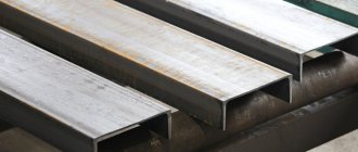
Moment of resistance of a channel when designing floors
When designing floors and load-bearing metal structures, one strength calculation of the load on the channel is not enough. To ensure the reliability of the designed structure, it is also necessary to calculate the rigidity of the channel. The deflection in this case should not exceed the permissible value. This profile check is mandatory when designing floors for residential and other premises. For example, let's take the same beam as before. The distributed load acting on it is 50 kgf/m or 500 N/m. The moment of inertia of the 10P channel has the value Ix = 175 cm4. When checking a beam for rigidity, its relative deflection is determined using the formula:
M – bending moment, N∙m L = 1000 cm – rod length E = 2.1∙105 MPa – modulus of elasticity of steel Ix = 175 cm4 – moment of inertia of the channel section
The moment of resistance of the channel, the bending moment is equal to: M = q∙L2/8 = 500∙102/8 = 6250 N∙m.
Then the relative deflection of the 10P channel will be: f/L = 6250∙1000/(10∙2.1∙105∙175) = 0.017 = 1/59
If we compare it with the permissible values regarding deflection according to SNiPs, then this channel cannot be used for interfloor ceilings, since the permissible value there is 1/200. Therefore, despite ensuring the strength of this design, it is necessary to select a larger channel profile and check it for rigidity.
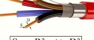
Load test of a trussed run
A channel is one of the types of shaped steel products. In cross section it has the shape of the letter “P”. This form provides the channel with such rigidity indicators that make it possible to use it in a wide variety of industries - from heavy engineering to the construction of country houses. Channels are used in automobile and carriage building, they are used to make various supports and fences, and they are used to strengthen entrance gates and window openings.
Permissible deflection of a metal beam
A beam is an element in engineering that is a rod that is loaded by forces acting in a direction perpendicular to the rod. The work of engineers often involves the need to calculate the deflection of a beam under load. This action is performed in order to limit the maximum deflection of the beam.
Types
Today, beams made from different materials can be used in construction. It can be metal or wood. Each specific case implies different beams. In this case, the calculation of beams for deflection may have some differences, which arise due to the difference in structure and materials used.
Wooden beams
Today's individual construction involves the widespread use of beams made of wood. Almost every building contains wooden floors. Wooden beams can be used as load-bearing elements; they are used in the manufacture of floors, and also as supports for floors between floors.
It's no secret that a wooden beam, like a steel beam, tends to bend under the influence of load forces. The deflection arrow depends on what material is used, the geometric characteristics of the structure in which the beam is used, and the nature of the loads.
The permissible deflection of the beam is formed from two factors:
- Correspondence between deflection and permissible values.
- Ability to operate the building taking into account deflection.
Strength and rigidity calculations carried out during construction make it possible to most effectively assess what loads the building can withstand during operation.
Also, these calculations make it possible to find out exactly what the deformation of structural elements will be in each specific case.
Perhaps no one will argue that detailed and most accurate calculations are part of the responsibilities of civil engineers, but with the use of several formulas and the skill of mathematical calculations, you can calculate all the necessary quantities yourself.
In order to correctly calculate the deflection of a beam, you must also take into account the fact that in construction the concepts of rigidity and strength are inseparable. Based on the strength calculation data, you can proceed to further calculations regarding rigidity. It is worth noting that calculating the deflection of a beam is one of the indispensable elements of calculating rigidity.
Please note that to carry out such calculations yourself, it is best to use large-scale calculations, while resorting to fairly simple schemes. It is also recommended to make a small margin in the larger direction. Especially if the calculation concerns load-bearing elements.
Calculation of beams for deflection. Work algorithm
In fact, the algorithm by which such a calculation is made is quite simple. As an example, we will consider a somewhat simplified calculation scheme, while omitting some specific terms and formulas. In order to calculate beams for deflection, it is necessary to perform a number of actions in a certain order. The calculation algorithm is as follows:
- A calculation scheme is drawn up.
- The geometric characteristics of the beam are determined.
- The maximum load on this element is calculated.
- If necessary, the strength of the beam is checked by bending moment.
- The maximum deflection is calculated.
As you can see, all the steps are quite simple and quite doable.
Drawing up a design diagram of a beam
In order to draw up a calculation scheme, you do not need much knowledge. To do this, it is enough to know the size and shape of the cross-section of the element, the span between the supports and the method of support. The span is the distance between two supports. For example, you use beams as supporting floor beams for the load-bearing walls of a house, between which there are 4 m, then the span will be equal to 4 m.
When calculating the deflection of a wooden beam, they are considered to be simply supported structural elements. In the case of a floor beam, a diagram with a load that is evenly distributed is adopted for the calculation.
It is denoted by the symbol q. If the load is concentrated in nature, then a circuit with a concentrated load, denoted F, is taken.
The magnitude of this load is equal to the weight that will put pressure on the structure.
Moment of inertia
The geometric characteristic, which is called the moment of inertia, is important when calculating the deflection of a beam. The formula allows you to calculate this value; we will give it a little below.
When calculating the moment of inertia, you need to pay attention to the fact that the size of this characteristic depends on the orientation of the element in space. In this case, an inversely proportional relationship is observed between the moment of inertia and the amount of deflection.
The smaller the moment of inertia value, the greater the deflection value and vice versa. This dependence is quite easy to track in practice.
Every person knows that a board laid on its edge bends much less than a similar board in a normal position.
The moment of inertia for a beam with a rectangular cross-section is calculated using the formula:
J=b*h3/12, where:
b – section width;
h is the height of the beam section.
Maximum load level calculations
The determination of the maximum load on a structural element is made taking into account a number of factors and indicators.
Usually, when calculating the load level, they take into account the weight of 1 linear meter of beam, the weight of 1 square meter of floor, the temporary load on the floor and the load from partitions per 1 square meter of floor. The distance between the beams, measured in meters, is also taken into account.
For an example of calculating the maximum load on a wooden beam, we will take the average values, according to which the weight of the floor is 60 kg/m², the temporary load on the floor is 250 kg/m², the partitions will weigh 75 kg/m². The weight of the beam itself is very easy to calculate, knowing its volume and density. Let's assume that a wooden beam with a cross-section of 0.15x0.2 m is used. In this case, its weight will be 18 kg/linear meter.
Also, for example, let’s take the distance between the floor beams to be 600 mm. In this case, the coefficient we need will be 0.6.
As a result of calculating the maximum load, we obtain the following result: q=(60+250+75)*0.6+18=249 kg/m.
When the value is obtained, you can proceed to calculating the maximum deflection.
Calculation of the maximum deflection value
When a beam is calculated, the formula displays all the necessary elements. It should be borne in mind that the formula used for calculations may have a slightly different form if the calculation is carried out for different types of loads that will affect the beam.
First, we present to your attention the formula used to calculate the maximum deflection of a wooden beam with a distributed load.
f=-5*q*l4/384*E*J.
Please note that in this formula E is a constant value, which is called the elastic modulus of the material. For wood, this value is 100,000 kgf/m².
f=-F*l3/48*E*J, where:
F – pressure force on the beam.
We also draw attention to the fact that the value of the elastic modulus used in the calculations may vary for different types of wood. Not only the type of wood has an impact, but also the type of timber. Therefore, a solid wooden beam, laminated veneer lumber or rounded log will have different elastic moduli, and therefore different maximum deflection values.
You can pursue different goals when calculating beams for deflection. If you want to know the limits of deformation of structural elements, then after completing the calculation of the deflection arrow, you can stop. If your goal is to establish the level of compliance of the found indicators with building codes, then they need to be compared with the data that is posted in special regulatory documents.
I-beam
Please note that I-beams are used somewhat less frequently due to their shape. However, we should also not forget that such a structural element can withstand much greater loads than an angle or channel, an alternative to which can be an I-beam.
Formulas for calculating beam deflection
The beam is the main element of the supporting structure of the structure. During construction, it is important to calculate the deflection of the beam. In real construction, this element is affected by wind force, loading and vibration. However, when performing calculations, it is customary to take into account only the transverse load or the applied load, which is equivalent to the transverse one.
How to build a wooden house. All documents
Foundation of a wooden house
Waterproofing a house with modern materials Waterproofing the foundation of a log house using the “old-fashioned” method Plinth, backfill, blind area Construction of a basement in a log house Materials and solutions for foundations and plinths Pile and slab foundations Strip foundations for a log house Columnar foundations: wooden (chairs) and stone Columnar foundations made of reinforced concrete pillars; TISE technology Preparing a site for a foundation Calculation of the foundations of a wooden house
Walls of a wooden house
General idea of the construction of walls from logs The principle of cutting walls Cutting corners of walls “into the claw” or “into the bowl” Cutting into the “paw” Walls made of timber Joints of walls made of timber Profiled and glued beams Other options for corner cuts Cutting window crowns Log house from rounded logs Walls with vertical bars; made of wooden bricks Caulking work Strengthening long walls Putting a log house in place Repairing walls of log and cobblestone houses Partitions in a wooden house
Windows, doors, stairs
Glued window structures Manufacturing and installation of window frames Manufacturing of window frames Assembling windows on screw ties Manufacturing of simple panel doors Manufacturing of panel doors Door frame, door cashing Porch of a wooden house Terrace of a wooden house Veranda, balcony of a wooden house Basic requirements for the construction of stairs Techniques for assembling wooden stairs Assembling a wooden house stairs
Calculation of the slope of the roof of the house Rafter options Connection of rafters Calculation of rafters; wooden eaves Requirements for sheathing Clay-straw (clay-reed) roofing Roofing made of wood chips Roofing made of plank in a wooden house Roofing made of slate (corrugated asbestos-cement sheets) Requirements for chimneys
Tools, work methods
Basic carpentry tools and preparing them for work Fastening, cutting and trimming logs; cutting into half a tree Marking timber; selection of quarters, grooves in logs Techniques for extending, splicing and joining logs Sawing, planing, drilling Workbench; wood gluing
Harvesting, storage and preservative of timber Plywood, various wood boards Edged lumber from 1m3 logs; how to cut a log Choosing a log; how to determine the volume of one log Properties of wood - what is worth considering About wood and its species in the construction of a wooden house How to arrange thermal insulation of a wooden house Features of the site: soil and groundwater level Which house is more comfortable: large or small Influence of the climatic zone and seasons on the construction of a house Why guide when planning a house
Formulas for calculating beam deflection
The beam is the main element of the supporting structure of the structure. During construction, it is important to calculate the deflection of the beam. In real construction, this element is affected by wind force, loading and vibration. However, when performing calculations, it is customary to take into account only the transverse load or the applied load, which is equivalent to the transverse one.
When calculating, the beam is perceived as a rigidly fixed rod, which is installed on two supports. If it is installed on three or more supports, calculating its deflection is more complex, and it is almost impossible to do it yourself.
The main load is calculated as the sum of forces that act in the direction of the perpendicular section of the structure. A design diagram is required to determine the maximum deformation, which should not exceed the limit values.
This will allow you to determine the optimal material of the required size, cross-section, flexibility and other indicators.
Tabular data
Analysis of statistics and calculations based on data on the load capacity of coniferous wood (averaged) made it possible to compile a table of distances between joists and derive a relationship between the thickness of the flooring boards (slabs) and the pitch of the supporting beams.
Important: if the room’s traffic is increased or heavy furniture (equipment) is planned to be installed, adjustments must be made. At the same time, the thickness of the floorboard increases, as does the cross-section of the beams, and the size between the joists decreases
To install a floor on a solid (reinforced concrete slab) base, the minimum permissible section of the beams and the maximum distance between them are taken. When creating a deck in a frame or wooden house, not only the payload on the deck is taken into account, but also the dead weight of the structure - beams, rough decking, heat, sound and waterproofing, and finishing.
ISOPROMAT.ru
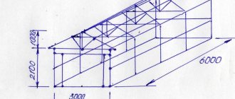
Perform a full strength calculation and check the rigidity of a statically determinate I-beam, double-support (Fig. 1) with the following data: F=40kN, q=30 kN/m, a=0.8 m, l=4m, permissible normal and shear stresses: [ σ ]=160 MPa and [ τ ]=100 MPa, permissible beam deflection [f]= l/400
Preparing a design diagram for solving the problem:
Determination of support reactions
An example of determining support reactions for a beam is discussed in detail here
And also in our short video tutorial:
Construction of diagrams Q and M
Video about calculating Q and M values for plotting:
Based on these data, diagrams of Q and M were constructed.
A short video on how to build diagrams:
Selection of the cross-section of an I-beam
Since Mmax = 45 kNm, then
According to the assortment, we select I-beam No. 24, for which Wx = 289 cm 3, Ix = 3460 cm 4, Smax = 163 cm 3, h = 24 cm, bп = 11.5 cm, t = 0.95 cm, d = bc = 0.56 cm, h = h-2t = 22.1 cm.
This I-beam will operate at the maximum normal stress in the extreme fiber of the dangerous section.
Checking the beam section using tangential stresses
Since Qmax = 68 kN, then
Construction of diagrams of normal σ and tangential τ stresses in an unfavorable section of the beam:
In terms of principal stresses, the section above the left support is unfavorable, in which:
The stress values at various points along the I-beam height are summarized in Table 1
Checking beam strength by principal stresses
The most dangerous point in the unfavorable section is point 3. At this point σ 1 = 118 MPa and σ 3 = -16 MPa. We check the strength at this point using the third strength hypothesis according to the inequality σ 1 - σ 3≤ [ σ ].
Since 118 - ( -16) = 134 θ
whence θ = -8.48∙10 -3 radians.
Deflection in the span at z=l/2=4/2=2 m.
The deflection at the end of the console is determined similarly at z = l + a = 4 + 0.8 = 4.8 m.
Making calculations
Having decided on the type of structure, it is necessary to prepare a calculation of the wooden floor, first of all, the required number of beams, taking into account the required section and arrangement. Accurate calculations will allow you to avoid unpleasant surprises during operation.
The length of the beam is calculated based on the size of the opening and the chosen method of fastening. For the traditional method, the total length includes the width of the opening and the length of the parts placed in the niche. If fasteners are used, the length of the beam is equal to the width of the opening.
The distance between beams, or pitch, is usually more than 60 cm and less than 1 m, but can be placed more often. The quantity is calculated by dividing the length of the opening by the selected step with the obligatory displacement of the outer beams from the wall by at least 5 cm.
for rectangular buildings
a) For walls of rectangular buildings, the peak positive value of the aerodynamic coefficient cp
,
+=
1,2.
b) Peak values of the negative aerodynamic coefficient cp
,
–
for walls and flat coverings (Figure D.24) are given in Table D.12.
Table D.12
| Plot | A | B | C | D | E |
| cp ,– | –2,2 | –1,2 | –3,4 | –2,4 | –1,5 |
24