As a result of purchasing a new computer, old power supplies may remain idle, which can be used to create a home workshop. With some effort, you can assemble a welding machine from computer power supplies with your own hands. Such equipment will be useful when performing non-professional tasks of joining metals at home.
The financial investment will not be noticeable, and the time spent on remaking the power source will be fully justified by the appearance of a new type of equipment in the arsenal. We will tell you how to do this work yourself.
Mini spot welding machine with power supply voltage 12V
Hello. In this article I will tell you how to make a simple spot welding machine powered by 12V. Most of the parts needed to assemble the device can be obtained from faulty switching power supplies or boards of old TVs and monitors.
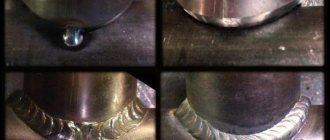
Materials and tools: - breadboard or foil PCB; — ferrite ring; — two field-effect transistors IRF3205 or similar; — two 5.6 kOhm resistors; — two resistors 470 Ohm 2 W; — two zener diodes at 6.2V; — two ultra-fast diodes HER108; — capacitor 0.68 μF; — metal powder ring for the throttle; - winding wire with a diameter of 0.4-0.7 mm; — winding wire with a diameter of 1-1.5 mm; - solder; — rosin (or other flux for soldering radio components); — installation wires; - wire cutters;
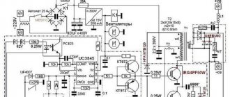
In the diagram you can see two diodes D1 and D2, these are ultra-fast diodes, as the name suggests, their difference is a much higher response speed than conventional rectifier diodes. I used HER108 diodes, but they can be replaced with analogues UF1004, UF1007, HER308 or others. When choosing diodes, you should pay attention to such a parameter as the recovery time, this indicator should be less than 100 ns.
You can start assembling the device by winding the transformer. Two ferrite rings M2000NM1-B with dimensions 31x18.5x7 were used as the core.
The number of turns may be less (but preferably at least seven), and the cross-section of the wire depends more on the remaining elements of the circuit. If the inductor in the finished device gets very hot during operation, the cross-section of the wire should be increased and/or the number of turns reduced.
Next, you should proceed to assembling the circuit on the board. It is better to assemble the circuit from the center of the board to the edges. So that already installed parts do not interfere with the installation of subsequent ones.
It is important to remember that the metal substrate of the transistor, to which the radiator is attached, is integral with the drain of the transistor. Therefore, when using a common heatsink for both transistors, it is necessary to install an insulating substrate between the body of the semiconductor device and the heatsink, otherwise a short circuit will occur. Also, even when using separate radiators, you should ensure that the radiator does not come into contact with the tracks on the board or the leads of other elements.
Next, you can proceed to the manufacture of the secondary winding of the transformer. It consists of one turn with three strands of winding wire with a diameter of 1 mm. The output current and voltage depend on the number of turns and cross-section of the wire in the secondary winding. Therefore, I deliberately did not secure the secondary winding with epoxy glue or electrical tape, so that, if necessary, I could easily change the number of turns or cross-section of the wire, changing the output characteristics of the device. Screw terminals are installed on the winding terminals.
DIY crafts for car enthusiasts
Hello everyone, in this article I will tell you in detail how you can make a simple converter from 12 volts to 220 volts using available components. Powerful, good circuits, as a matter of fact, are difficult even for professionals, and are generally not achievable for beginners, so today we will consider a design option for a step-up voltage converter, which can be made from parts of a non-working power supply from a computer.
The scheme was specially chosen to be the simplest so that everyone could repeat it. Our circuit does not require additional configuration, I also decided to abandon the standard options based on a PWM controller, this would complicate the task and make configuration difficult.
Attention - the circuit is presented for informational purposes only, it does not have stabilization, so the output voltage will deviate from the declared 220 volts. It also does not have any protection, and the output is direct current, which means that such an inverter cannot power AC motors and network transformers.
Connecting a soldering iron, small incandescent lamps, economy lamps, but again using such a circuit for domestic purposes is not a good idea.
Do we have a normal donor? non-working computer power supply, from this unit we will need: - Power, pulse transformer, - Capacitor, - Group stabilization choke and a few more components, which we will talk about along the way.
In order to remove these components, we need to remove the board, that is, separate the board from the case, this is done in a fairly simple way, unscrew the screws, cut the wires that go to the fan and pull out the board.
In order to unsolder the transformer, I will naturally use a soldering iron and a desoldering pump; we also need to unsolder, in addition to the indicated components, the radiator on which the main power transistors are located,
plus insulating gaskets and washers for them.
In addition to the main spare parts that we removed from the computer power supply, we need two resistors with a power of 1-2 watts, with a resistance from 270 to 470 Ohms. Next, we will need two diodes of the UF5408 type; in principle, any ultra-phase with a current of at least 1 ampere and a voltage of 400 volts and higher is possible.
Two zener diodes with a stabilization voltage from 5.1 to 6.8 volts, preferably 1 and 2 watts. N-channel field effect transistors can be used as a variant of IRF840, but I would recommend the more powerful IRFP460 or 250 from the same line, but in my version I will use 18 amperes 600 volts, such as 18N60.
The next ingredient is our choke,
in principle, there are several independent windings on the group stabilization choke, they can, in principle, be wound up, I took a bite, leaving only the power winding. If the choke is wound from scratch, then the winding consists of a 1.2-1.5 mm wire and contains from 7 to 15 turns.
So the transformer, we have a secondary, output winding and a primary, pay attention to the separate tap (wire) and two right contacts,
we put a mark next to them,
that is, the power terminals from the transistors are connected to these contacts, then we connect our 1 mF capacitor in parallel to the same contacts from the transformer.
Then the installation begins, the transistors are actually installed on the heat sink, I will not use any insulation, since the transistor cases are already pre-insulated from the factory.
I decided, in principle, not to etch any boards, but simply to assemble everything using a hinged mounting for maximum ease of assembly. The assembled circuit diagram looks something like this:
Now we just need to connect a low-power incandescent lamp to the output winding, drop the power to check the circuit’s functionality.
Now we need to unsolder two large electrolytic capacitors from the computer power supply, they are located in absolutely any computer power supply, the capacity varies, the voltage is 200 volts.
Based on these capacitors and diodes, we will create a symmetrical voltage multiplier or simply a voltage doubler, since the output voltage from the secondary winding of the transformer is around 100 volts and needs to be raised.
To do this, we will use a multiplier, which will double it.
In addition to these capacitors, we also need two diodes, in my version UF5408,
in principle, you can use any diodes rated at 400-600, or even better, 1000 volts with a current above 2-3 amperes.
A small incandescent lamp with a power of 60 watts burns with full heat. Well, that seems to be all, on this note our converter is ready for work)))
In conclusion, I want to say that the circuit operates in a wide range of supply voltages, in principle, work starts from 6 volts, simplicity and accessibility are the main advantage of the circuit, it is recommended to supply power through a 15-20 ampere fuse.
In the diagram I also drew resistors, which are capacitors shunted by these resistors; I did not put them in my project, but I definitely advise you to do so.
Author; Aka Kasyan
Popular;
- Simple voltage regulator on LM317, circuit
- LED battery indicator diagram for beginners
- Boost converter, DIY circuit
- Powerful converter from 12V to 5V 5 amps
- Why is the LED in the car blinking and what should I do?
- How to convert the “Krona” to a battery in a multimeter
- A simple laboratory power supply made from an old computer power supply.
- A simple diagram of a powerful laboratory power supply.
Making a welding inverter from a computer power supply with your own hands
Currently, not only professionals, but amateur welders work with inverter welding using modern equipment. An inverter is used very often; almost everyone has one.
Do you want to cook, but don’t have the money to buy equipment? Assembling an inverter with your own hands will help solve this problem.
We have already described how to assemble a welding machine using the materials you have at hand on this site. Today we will talk about assembling a welding inverter from a computer power supply. The necessary diagrams are provided in the article.
- Homemade device. Why him?
- Or should I buy it in a store?
- Inverter with power supply Technical characteristics
- Parts that are needed
- Assembly Features
Homemade device. Why him?
Is there a need to assemble a welding inverter from a computer power supply with your own hands, if any hardware store can offer a price of up to $50, saving you from suffering? – every craftsman asked himself this question.
This is true. At the same time, everything is not as obvious as it might seem.
The price of 50 dollars is an adventure when buying inverter devices. They are not suitable even for temporary use, let alone permanent use. What is the solution to the problem, you ask.
The cost of high-quality devices starts from $100. Then there is no talk of saving. For most citizens of our country, this amount is equal to half the salary, if not most of it.
For this reason, some are discussing assembling homemade welding inverters from a computer power supply. The cost of which is naturally lower than factory analogues. Everyone can personally choose which functions they need and what they will use to assemble them.
If you don't need a hot start or arc afterburner, there's no point in paying more.
The quality of the ingredients is the second factor to pay attention to. Factories, for the most part, assemble options that are far from high-quality spare parts, which in turn cost more during service repairs.
What you can save on, what parts to assemble the equipment from, you choose yourself.
The opinion of welders about the machine is also important. Not everyone likes modern technology. Some consider them too “sophisticated” and complex. They are not interested in overpaying for the brand and additional features.
You only need functional equipment for everyday use. Then, it is advisable to make a welding inverter from a computer power supply yourself. You can assemble not only a cheap and simple inverter, but one that will make factory equipment the envy of yours.
Everything you need, no extra parts.
Why assemble a homemade device?
Many craftsmen may ask the question: “Is it even worth assembling a device with your own hands from a computer power supply, if in a store you can easily buy a cheap inverter costing $50 and not have to worry?” Fair. But not everything is as obvious as it seems at first glance.
A purchased inverter welding unit that costs $50 is quite an adventure. These devices are not suitable even for occasional use, let alone constant welding. Let's say, throughout the entire summer season (and this is the period from April to November!). How to solve this problem? Buy the device for at least $100. But in this case, there is no question of saving. For many compatriots, $100 is half their salary, if not more.
Or should I buy it in a store?
Naturally, you can give facts why it is not worth assembling a welding inverter with your own hands from just anything. It is necessary not only to stock up on patience and free time.
It is very important to have knowledge of electrical engineering, to understand and distinguish the principles of operation of electrical appliances, and to understand circuits. You can always study these questions if you lack knowledge.
It is enough to set aside a few weeks to read specific literature. There are many videos on the Internet that will help you quickly finish your training, present simple, clear examples and help you assemble a really high-quality welding inverter from a computer power supply.
Inverter with power supply
Specifications
Resonant - this is exactly the kind of welding inverter from a computer power supply you will be able to assemble by following the instructions in this article. The range of welding currents is 5-120 Amps. Voltage 90V. When using electrodes with a diameter of 2 mm, there is no interruption of work.
However, when working with electrodes with a diameter of 3 mm, they require at least 2 minutes of rest after 10 minutes of continuous work. These figures may vary depending on the ambient temperature.
The weight is no more than two kilograms, so carrying it will be easy. Falling characteristic. The current intensity is adjusted smoothly. The structure includes 4 boards: control unit, main board, power board and capacitors.
From personal experience I can say that for garage and country work, a welding inverter from a computer power supply is excellent.
Parts that are needed
Let's start with the theory. Let us immediately note that the computer unit is not the best thing for a welding machine. The power supply is fundamentally different from the inverter. The unit can be configured to operate as an inverter.
The finished equipment will not be easy to assemble, and its performance will be much lower. Therefore, out of the entire power supply unit, we use only the case. Some things can be bought at radio markets, and some parts can be removed from an old personal computer.
Welding machine from a computer power supply - a cheap solution for an electrician
Very often, welding work requires an inverter, thanks to which you can get high-quality seams and not take risks when working with gas welding. But purchasing such a device is associated with significant costs, so you can try making a welding machine from a computer power supply. For this you need not only spare parts, wires and a soldering iron. But also skills in electrical engineering, without which you can burn electrical wiring or get an electric shock.
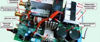
The main components of the welding machine design.
Assembly, installation and subsequent testing can only be carried out if you have experience in rewinding transformers, assembling circuits and creating electrical devices with your own hands. If such knowledge is absent, then it is best to purchase a ready-made inverter and not expose yourself or others to danger.
- Basic installation tools
- Selecting a transformer for a welding machine
- Recommendations for installing other parts of the circuit
- Installing a soldered chip into the case
Sine wave
The signal shape at the output of a car inverter is generated by a high-frequency generator. A sine wave can be of two types:
- modified sine wave;
- pure sine wave, pure sine wave.
Not every electrical device can work with a modified sine wave, which has a rectangular shape. Some components change their operating mode, they can heat up and start to get dirty. You can get something similar if you dim an LED lamp whose brightness is not adjustable. The crackling and flashing starts.
Expensive DC AC step-up voltage converters 12V-220V have a pure sine wave output. They cost much more, but electrical appliances work great with it.
Basic installation tools
If you have experience and knowledge in the field of electrical engineering, then you can explore several options on how to make a welding machine from a computer unit. Basic tools that will be needed for all types of assembly:
- soldering iron or soldering station;
- tester;
- multimeter;
- electrical insulating tape;
- solder;
- screwdrivers with different tips;
- pliers;
- screws;
- screwdriver or drill;
- crocodiles;
- wires of the required cross-section.
To recreate the circuit of the welding machine, you will need all the spare parts indicated in the circuit, getinaks and solutions for transferring the printed circuit board to the workpiece.
To make your work easier, you can purchase an electrode holder and welding cables at the store. You can do it yourself by selecting wires of the appropriate cross-section and soldering crocodiles to them, remembering to observe the polarity.
Welding inverter circuit.
If you have a non-working computer system unit, then you need to remove the main battery from it and prepare it for dismantling. Sometimes, to create a powerful welding machine, they even use the system unit itself, installing wheels on it at the bottom and increasing the number of ventilation holes. The advantage of computer cases is that they are lightweight, easy to cool and already have ventilation.
The welding machine will require disassembling the power supply.
The main things that can be used from it are the fan, the housing itself and some spare parts. But it all depends on the modes in which the cooling operates. The fan must be checked for functionality and tested in several modes. It is advisable to install another one of the same or more powerful so that the welding machine does not overheat. To monitor the temperature of the inverter, you need to install a thermocouple.
But first you need to take care of the handle, which will make the welding machine from a computer power supply convenient to use. To do this, you need to remove all the spare parts from the power supply and attach a handle selected for size and convenience to the upper end. You need to drill holes in the power supply and secure it with screws, which must be correctly selected in length (too long ones will interfere with the internal circuit, which is unacceptable).
The welding machine must have very good cooling, so several additional holes need to be drilled in the power supply housing.
The duration of operation of a homemade inverter will depend on the quality of ventilation.
Add a link to a discussion of the article on the forum
RadioKot >Schemes >Power >Converters and UPS >
| Article tags: | Add a tag |
12-220V converter for powering LDS from a computer power supply.
Author: Timofey Nosov Published 11/21/2007
ATTENTION!!! Before repeating this device, it is strongly recommended that you familiarize yourself with this topic in our Forum.
This converter is used to power fluorescent lamps (FLLs) with electronic ballast. Electronic ballasts are separate devices that replace low-frequency chokes. As a rule, such ballasts are found in the fittings of ready-made LDS lamps. The converter is guaranteed and reliable to work with ballasts of both powerful and “weak” lamps. The converter is also used to power “economical” base-type LDS; it was actually assembled for the purpose of autonomous, bright and economical lighting of the house, garage, and car interior. I decided not to assemble the electronic ballast but to use a ready-made one, because... the hemorrhoids-result ratio was in favor of ready-made solutions (it’s like making an incandescent lamp on your knees in our age).
Brief comments on the diagram. This is a push-pull pulse converter assembled on a TL494 PWM controller (a complete domestic analogue of 1114EU4), which makes the circuit quite simple. At the output there are highly efficient rectifier diodes that double the voltage according to the Delon or Greinmacher circuit (I didn’t want to swear). The output, of course, is constant voltage. For electronic ballasts, constant voltage and switching polarity are not relevant, because in the ballast circuit there is a diode bridge at the input (although the diodes there are not as “fast” as in our converter). The converter uses a ready-made high-frequency step-down transformer from the computer power supply (in general, almost all the parts used in this circuit can be torn out from an unnecessary or faulty computer power supply), but in our converter it will become a step-up transformer. The step-down transformer can be taken from both AT and ATX power supplies. From my experience, the transformers differed only in size, but the location of the terminals was the same. A dead power supply unit (or a transformer from it) can be found in any computer repair shop. You can wind the transformer yourself. Personally, my patience now is enough to manually wind no more than 20 turns, although in childhood I could wind a contour coil of 100 turns for a transistor receiver; the years take their toll. So, we find a suitable ferrite ring (outer diameter approximately 20-30 mm). The turns ratio is approximately 1:1:20, where 1:1 is two halves of the primary winding (10+10 turns), and :20 is, respectively, a secondary winding of 200 turns. First, the secondary is wound - evenly 200 turns with a wire with a diameter of 0.3-0.4 mm. Then, evenly, two halves of the primary winding (we wind 10 turns, make a middle tap, then wind the remaining 10 turns in the same direction). For half-windings I use stranded, silver mounting wire with a diameter of 0.8 mm (you don’t have to force it and use another wire, but stranded and soft is better). I offer another option for manufacturing (remaking) a transformer. You can purchase the so-called. “electronic transformer” for 12 volt halogen lamps for lighting ceilings and furniture (in lighting equipment stores it costs from 80 rubles). It contains a suitable transformer on the ring. You just need to remove the secondary winding, which consists of a dozen turns. And the half-windings can be wound differently - we fold a piece of wire (calculate the length) in half and wind it with the double folded wire; We cut the middle of the wire (the bend point) - we get the so-called two ends (or two beginnings) of windings. To the end of one wire we solder the beginning of another - we get a common point of the half-windings. I assure you that such a transformer works for me. It should be noted that a computer transformer works great in an “electronic transformer” circuit.
Conversion frequency is about 100 kHz (for calculation of the operating frequency, see the documentation for TL494). C1 is 1 nanofarad, or 1000 picofarad, or 0.001 microfarad (all options for capacitance values are equal); on the case the coding is 102; I set it to 152 - it works, but, I assume, at a lower frequency. R1 and R2 - set the width of the output pulses. The circuit can be simplified and these elements not installed, while the 4th contact of TL494 is set to negative; I don’t see the need to rape transistors with wide pulses. R3 (together with C1) sets the operating frequency. We reduce the resistance R1 - we increase the frequency. We increase the capacitance C1 - we reduce the frequency. And vice versa. Transistors are high-power MOS (metal-oxide-semiconductor) field-effect transistors, which are characterized by shorter response times and simpler control circuits. IRFZ44N, IRFZ46N, IRFZ48N work equally well (the higher the number, the more powerful and more expensive). The converter uses HER307 diodes (304, 305, 306 are suitable). Domestic KD213 work great (more expensive, larger and more reliable). The output capacitors can be of smaller capacity, but with an operating voltage of 200 V. Capacitors from the same computer power supply with a diameter of no more than 18 mm were used (or edit the printed circuit board design). Install the chip on the panel; it will be easier to live this way.
Setup comes down to carefully installing the microcircuit into the panel. If it doesn’t work, check for the presence of 12 V supply voltage. Check R1 and R2, are they confused? Everything should work. A radiator is not needed, because prolonged operation does not cause noticeable heating of the transistors. And if you want to install it on a radiator, then, be careful, do not short-circuit the flanges of the transistor housings through the radiator. Use insulating gaskets and bushing washers from a computer power supply. For the first start, a radiator will not hurt; at least the transistors will not immediately burn out in the event of installation errors or a short circuit at the output, or in the event of an “accidental” connection of a 220 V incandescent lamp. The power supply of the circuit must be convincing, because The current consumption of one copy of the “economical” LDS from a sealed acid battery was 1.4 A at a voltage of 11.5 V; total 16 W (although the lamp packaging says 26 W). Protection of the circuit from overload and reverse polarity can be implemented through a fuse and a diode at the input. Be careful!
The output of the circuit is high voltage and can cause a very serious shock. Then don't say you didn't warn me. Capacitors hold a charge for more than a day - tested on people. There are no discharge circuits at the output. Short-circuiting is not allowed; discharge either with a 220 V incandescent lamp or through a 1 mOhm resistor. Converter photo:
I “cooked” the transformer in boiling water and tried to disassemble it, but to no avail, as you can see - the top of the ferrite is slightly chipped; It was a shame to throw it away, now it’s in this board.
As always, my case is the most unfinished part of the finished device. The lamp shines too brightly, so the photo, no matter how hard I tried, turned out to be overexposed.
Files:
Printed circuit boards in Sprint Layout format: Option 1. Option 2.
As usual, we put the questions here.
| What do you think of this article? | Did this device work for you? | |
| 95 | 2 | 4 |
| 7 | 3 |
Selecting a transformer for a welding machine
For a circuit that will allow you to make a welding machine from a computer power supply, you will need 3 transformers. They can be purchased based on the names - E20, Kx20x10x5 and ETD 59. But it will be easier to wind them yourself, focusing on the number of turns and other information indicated in the diagram. A current transformer K17x6x5 is also required.
Regarding the manufacture of transformers, you only need an enamel wire, and a new f1.5 or f2. There is no way to do without winding on getinax coils, crimping them with wooden blocks and impregnating them with epoxy resin.
To assemble a device from a computer power supply, you can use a transformer from a microwave oven. Since the voltage on the secondary winding is about 2 kV, it is necessary to reduce the number of turns. To do this, you need to make an additional calculation, which can be done using a special online electrician calculator or find a book on electrical engineering with the corresponding section. But for the sake of such savings, changes will have to be made to the existing scheme.
The procedure for assembling the welding machine
First of all, to create a welding machine from a computer power supply, you need to remove the power source from the computer case and disassemble it. The main elements that can be used from it are a few spare parts, a fan and standard case plates. It is important to take into account the cooling operating mode. This determines what elements need to be added to ensure the necessary ventilation.
Diagram of a transformer with primary and secondary windings.
The operation of a standard fan, which will cool the future welding machine from a computer unit, must be tested in several modes. This check will ensure the functionality of the element. To prevent the welding machine from overheating during operation, you can install an additional, more powerful cooling source.
To control the required temperature, a thermocouple should be installed. The optimal temperature for operating the welding machine should not exceed 72-75°C.
But first of all, you should install a handle of the required size on the welding machine from a computer power supply for carrying and ease of use. The handle is installed on the top panel of the block using screws.
It is important to choose screws that are optimal in length, otherwise too large ones may affect the internal circuit, which is unacceptable. At this stage of work, you should worry about good ventilation of the device. The placement of elements inside the power supply is very dense, so a large number of through holes should be arranged in it in advance. They are performed with a drill or screwdriver.
Next, you can use multiple transformers to create an inverter circuit. Typically, 3 transformers such as ETD59, E20 and Kx20x10x5 are chosen. You can find them in almost any radio electronics store. And if you already have experience creating transformers yourself, then it’s easier to do them yourself, focusing on the number of turns and the performance characteristics of the transformers. Finding such information on the Internet will not be difficult. You may need a current transformer K17x6x5.
Methods for connecting a welding inverter.
It is best to make homemade transformers from getinax coils; the winding will be enamel wire with a cross-section of 1.5 or 2 mm. You can use 0.3x40 mm copper sheet, after wrapping it in durable paper. Thermal paper from a cash register (0.05 mm) is suitable; it is durable and does not tear so much. The crimping should be done from wooden blocks, after which the entire structure should be filled with “epoxy” or varnished.
When creating a welding machine from a computer unit, you can use a transformer from a microwave oven or old monitors, not forgetting to change the number of turns of the winding. For this work, it would be useful to use electrical engineering literature.
As a radiator, you can use PIV, previously cut into 3 parts, or other radiators from old computers. You can purchase them in specialized stores that disassemble and upgrade computers. Such options will pleasantly save time and effort in searching for suitable cooling.
To create a device from a computer power supply, you must use a single-cycle forward quasi-bridge, or “oblique bridge”. This element is one of the main ones in the operation of the welding machine, so it is better not to save on it, but to purchase a new one in the store.
Printed circuit boards can be downloaded on the Internet. This will make recreating the circuit much easier. In the process of creating the board, you will need capacitors, 12-14 pieces, 0.15 microns, 630 volts. They are necessary to block resonant current surges from the transformer. Also, to make such a device from a computer power supply, you will need capacitors C15 or C16 with the brand K78-2 or SVV-81. Transistors and output diodes should be installed on radiators without using additional gaskets.
During operation, you must constantly use a tester and a multimeter to avoid errors and to assemble the circuit faster.
Electrical circuit of a semi-automatic welding machine.
After manufacturing all the necessary parts, they should be placed in the housing and then routed. The temperature on the thermocouple should be set to 70°C: this will protect the entire structure from overheating. After assembly, the welding machine from a computer unit must be pre-tested. Otherwise, if you make a mistake during assembly, you can burn all the main elements, or even get an electric shock.
On the front side, two contact holders and several current regulators should be installed. The device switch in this design will be a standard computer unit toggle switch. The body of the finished device after assembly requires additional strengthening.
Recommendations for installing other parts of the circuit
Due to the fact that this circuit has already been repeatedly used to assemble a welder that has become a replacement for an inverter, there are some comments about it. It is recommended to replace 15tb60 diodes with 25tv60, and it is best to install 150ebu02 diodes in groups of 2.
To save money on the radiator, you can take the PIV and cut it into 3 parts. It is mandatory to use a converter - a single-cycle forward-flow quasi-bridge. Or, more simply, an “oblique bridge”, without which not a single inverter can be assembled. It’s better not to skimp on this spare part and buy a good quality one, not a used one.
Installing a soldered chip into the case
After all the necessary parts have been manufactured and assembled into a single whole, you need to place them in the housing and make the correct wiring. The power supply on/off switch is used as a switch for the future device. On the front panel you need to provide a current regulator and contact holders for connecting welding wires. The housing must be carefully and firmly secured. The end result should be a product that looks something like this.
Such production of a welding machine will allow significant savings, but will require a lot of effort. But after successfully assembling the first inverter, it will be possible to make changes to the circuit, invent your own models (more powerful or lighter) and make such custom-made devices familiar. And this can be a great way to earn extra money.
Making a welding inverter from a computer power supply
As a result of purchasing a new computer, old power supplies may remain idle, which can be used to create a home workshop. With some effort, you can assemble a welding machine from computer power supplies with your own hands. Such equipment will be useful when performing non-professional tasks of joining metals at home.
The financial investment will not be noticeable, and the time spent on remaking the power source will be fully justified by the appearance of a new type of equipment in the arsenal. We will tell you how to do this work yourself.
Converter 12V - 220V from computer power supply parts.
The scheme discussed in the article is designed for informational purposes. This is a simple circuit without a PWM controller, which complicates it. When assembled correctly, it does not require configuration and will work immediately. But simplicity also has disadvantages: the output voltage is not stabilized, the circuit does not have any protection, and the output current is constant.
Those. This converter cannot power AC motors or devices with a mains transformer. You can connect a soldering iron, an incandescent lamp and an economy lamp. But still, you should not use such a scheme for domestic purposes.
The parts donor will be a faulty computer power supply. We disassemble the case and remove the board by unscrewing the 4 screws in the corners. We unsolder the power pulse transformer, a toroidal group stabilization choke, 2 electrolytic capacitors 330 µF x 200 V (their capacity may differ in different power supply models), a non-polar capacitor 1 µF. Next, we remove the radiators on which the power transistors are located; you may also need gaskets and washers from under these transistors.
In addition you need:
• 2 resistors with a nominal value from 270 to 470 Ohms and a power of 2W, • 2 diodes UF5408 or other ultrafast (UF) with a current of at least 1A and a voltage of at least 400V, • 2 zener diodes at 6.8V, a power of at least 1W, • 2 N- channel transistor IRF840 or IRFP460 or IRFP250 or 18N60 (18A, 600V).
The inductor wound on a torus has several windings; we only need a power winding, which will be a current limiter. The rest can be unwinded or you can simply bite the conclusions so as not to interfere. If such a choke is wound from scratch, then you should wind from 7 to 15 turns with 1.2-1.5mm wire.
The assembly will be surface-mounted, without a printed circuit board, for maximum simplicity. Let's consider a power transformer. On one side there are 2 terminals, this will be the secondary winding. On the other side, where the so-called “braid” is, there are several conclusions. We use 2 pins on the left, to which we will connect the power pins of the transistors. We also connect a 1 µF capacitor in parallel to this winding.
We install transistors on the heat sink. Depending on the type of transistor housing (insulated drains or not), insulating spacers and washers may be needed under the mounting screws. Then we bend the drain leads and solder them to the two outer terminals of the transformer. Solder the zener diodes and resistors.
Now, to check the functionality of the assembled part of the circuit, you need to connect an incandescent lamp to the secondary winding and apply voltage from the battery to the input. If everything is assembled correctly, the light bulb will light up, but with incomplete brightness. This is because the output voltage on the secondary winding is about 100V, but we need 220V. Therefore, we add a voltage doubler consisting of 2 electrolytic capacitors and 2 UF5408 diodes. We also install 330 kOhm shunt resistors in parallel.
Now the 60W light bulb is on at full brightness. It is recommended to install a 15-20A fuse at the input of the circuit. In conclusion, I note that the circuit operates in a wide range of supply voltages, starting from 6V.
Video:
Required parts and equipment
Inverter welding machines are complex electronic devices that are not possible to assemble independently without certain qualifications and the availability of the necessary equipment. Therefore, you will have to rent expensive equipment while debugging and assembling the unit.
You should start creating a welding machine from a computer power supply by selecting a suitable and simple electrical circuit so that the selection of semiconductor and other components does not need to be recalculated. Low-power inverter units consume a current of no more than 15 A from the network.
The network cable can be saved, but the fan must be replaced with a more powerful one, which will ensure good cooling of the radiators of the power elements. In addition, you will need the following tools and equipment:
- foil PCB for boards or its substitutes;
- wires of the required cross-section and length;
- semiconductor elements, resistances and capacitors of the required value, according to the selected circuit;
- a transformer with suitable characteristics, which may have to be adapted to the required parameters;
- radiators for power elements;
- soldering iron with solder and rosin or flux;
- screwdrivers, pliers, fasteners, drill and insulating material;
- multimeter, oscilloscope.
It is extremely important to carry out installation in strict accordance with the selected circuit, observing polarity and checking for leaks.
Inverter assembly sequence
When preparing for the final assembly of the inverter, you need to take care of the presence of a temperature sensor designed to operate when heated from 70 to 75 o C. In addition, you need to take care of the sockets for the power cable and the electrode holder with wires with a cross-section of 35 mm 2, for efficient supply of current to the welding machine. arcs. Then, having prepared all the necessary elements, we begin installation in the following sequence:
- we position the fan and cooling radiators so as to ensure the most efficient air flow, and provide reliable fastening;
- securely fasten the transformer and capacitor board;
- install the control circuit board and related parts;
- we install an anti-stick and hot start device;
- we check for short circuits the contacts through which the circuit components are powered;
- We carry out final wiring and installation of fuses and thermoelements;
- We carry out the final adjustment using a multimeter and an oscilloscope, taking into account the calculated parameters;
- We set the required welding current and carry out trial work.
How to make a welding inverter from a computer power supply with your own hands?
A DIY welding inverter made from a computer power supply is becoming increasingly popular among both professionals and amateur welders. The advantages of such devices are that they are comfortable and lightweight.
Welding inverter device.
The use of an inverter power source allows you to qualitatively improve the characteristics of the welding arc, reduce the size of the power transformer and thereby lighten the weight of the device, makes it possible to make adjustments smoother and reduce spatter during welding. The disadvantage of an inverter-type welding machine is its significantly higher price than its transformer counterpart.
In order not to overpay large sums of money in stores for welding, you can make a welding inverter with your own hands. To do this, you need a working computer power supply, several electrical measuring instruments, tools, basic knowledge and practical skills in electrical work. It would also be useful to acquire relevant literature.
If you are not confident in your abilities, then you should go to the store for a ready-made welding machine, otherwise, with the slightest mistake during the assembly process, there is a risk of getting an electric shock or burning all the electrical wiring. But if you have experience in assembling circuits, rewinding transformers and creating electrical appliances with your own hands, you can safely begin the assembly.
Operating principle of inverter welding
Schematic diagram of the inverter.
The welding inverter consists of a power transformer that reduces the network voltage, stabilizer chokes that reduce current ripple, and an electrical circuit block. MOSFET or IGBT transistors can be used for the circuits.
The principle of operation of the inverter is as follows: alternating current from the network is sent to the rectifier, after which the power module converts direct current into alternating current with increasing frequency. Next, the current enters the high-frequency transformer, and the output from it is the welding arc current.
Voltage converter design
Let's consider the design of a conventional step-up voltage converter from 12 to 220. The operating principle for all modern inverters will be the same. The high-frequency PWM controller sets the operating mode, frequency and amplitude. The power part is made of powerful transistors, the heat from which is transferred to the device body.
At the input of the converter from 12 to 220 there is a fuse that protects the car battery from short circuits. A thermal sensor is attached next to the transistors, which monitors their heating. If the 12v-220v inverter overheats, an active cooling system consisting of one or more fans is turned on. In budget models, the fan can work constantly, and not just under high load.
Power transistors at the output
Tools required to make an inverter
To assemble a welding inverter from a power supply with your own hands, you will need the following tools:
TL494 voltage feedback circuit in a computer power supply.
- soldering iron;
- screwdrivers with different tips;
- pliers;
- wire cutters;
- drill or screwdriver;
- crocodiles;
- wires of the required cross-section;
- tester;
- multimeter;
- consumables (wires, solder for soldering, electrical tape, screws and others).
To create a welding machine from a computer power supply, you need materials to create a printed circuit board, getinaks, and spare parts. To reduce the amount of work, you should go to the store for ready-made electrode holders. However, you can make them yourself by soldering crocodiles to wires of the required diameter. It is important to observe polarity when doing this work.
Power converter circuits
A powerful inverter is mainly used to connect construction power tools during the construction of a summer house or hacienda. A low-power 500-watt voltage converter differs from a powerful 5,000-10,000-watt converter in the number of transformers and power transistors at the output. Therefore, the manufacturing complexity and price are almost the same; transistors are inexpensive. The power is optimally 3000 W, you can connect a drill, grinder and other tools.
I will show several inverter circuits from 12, 24, 36 to 220V. It is not recommended to install these in a passenger car; you can accidentally damage the electrics. The circuit design of DC AC converters 12 to 220 is simple, a master oscillator and a power section. The generator is made on the popular TL494 or analogues.
A large number of booster circuits from 12v to 220v for making with your own hands can be found at the link https://cxema.my1.ru/publ/istochniki_pitanija/preobrazovateli_naprjazhenija/101-4 In total there are about 140 circuits, half of them are boost converters with 12, 24 at 220V. Powers from 50 to 5000 W.
After assembly, you will need to adjust the entire circuit using an oscilloscope; it is advisable to have experience working with high-voltage circuits.
To assemble a powerful 2500 Watt inverter you will need 16 transistors and 4 suitable transformers. The cost of the product will be considerable, comparable to the cost of a similar radio designer. The advantage of such costs will be a pure sine output.
Sergey, hello! I have a question: I have a DC12->AC220 converter for 300W, I power my computer with it. Everything works fine for about 1-2 hours (consumption is approximately 120W). But when the converter lacks energy, it makes a wild squeak and immediately abruptly cuts off the output. At the same time, approximately 11.5 volts remain in the battery. The converter is Chinese, but in appearance it is quite good. The question itself is: why does this happen if there is still a lot of energy in the battery and how to improve this so that the converter sucks out at least half the energy. Ideally, it would also squeak a little before dying.