Morse cones
The Morse taper, proposed by inventor Stephen Morse, is the most commonly used tool mounting method.
The existing division into eight sizes, from KM0 to KM7, and nine shortened sizes allows the use of a tapered shank for various cutting tools, equipment and accessories. The taper in this case varies in the ratio from 1:19.002 (at an angle of 1°25′43″) to 1:20.047 (the angle at this ratio is 1°30′26″). KM7 is not recommended for use by domestic GOST 25557-82 and instead a metric cone No. 80 is used, for example, in the spindle hole of some lathes. The standard size of the cone as a tool shank depends on the installation method and purpose of the latter, and can be either shortened or Morse tapers or with a claw.
Basic information about shanks and their designation
There are several types of instrument cones. It may contain threads, a foot or do without them.
A thread can be cut at its end, which is made to secure the tool to the spindle using a pin. This is a special rod that prevents the tool from falling out. It can also be used to remove the product if it accidentally gets stuck in the spindle.
If the shank is made with a foot, then it holds the tool in the spindle due to the fact that it is secured in a special groove. The foot has two purposes: with its help it is easier to remove the product from the spindle, and it also creates a rigid fixation and there will be no turning.
You can also find a design with several grooves and holes. They have different depths and sizes. Their task is to supply cutting fluid to the cutting tool.
Tool shanks come in different designs and are designated by letter codes. Below is their transcript:
- BI – internal, there is a groove;
- BE – external, there is a foot;
- AI – internal, there is a hole along the axis;
- AE – external, there is a hole along the axis with a thread;
- BIK – internal, there is a groove and a hole for supplying cutting fluid (coolant);
- VEK – external, there is a foot and a hole for coolant supply;
- AIK – internal, contains holes along the axis and for coolant supply;
- AEK – external, contains an axial hole with a thread and a hole for coolant supply.
External and internal correspond to their names. Depending on the tool used, you should choose an external or internal version.
Morse and metric tapers with threaded hole
For reliable fixation of tools, such as cutters, a Morse taper with an internal threaded hole is used. Fixing (tightening) is performed using a pin, or a bolt if the tool is installed in the adapter sleeve. This design also allows for quick and convenient tool changes by squeezing out the tapered shank.
Basic dimensions of external tool metric and Morse tapers with threaded hole
| Cone name | N cone | Taper | D, mm | D1, mm | d, mm | l, mm | Lmax, mm | tmax, mm | M | t1, min, mm |
| Morse | 1 | 1:20,047 | 12,065 | 12,2 | 9 | 3,5 | 57 | 5 | M6 | 16 |
| 2 | 1:20,020 | 17,780 | 18 | 14 | 5 | 69 | 5 | M10 | 24 | |
| 3 | 1:19,992 | 23,825 | 24,1 | 19 | 5 | 86 | 7 | M12 | 28 | |
| 4 | 1:19,254 | 31,267 | 31,6 | 25 | 6,5 | 109 | 9 | M16 | 32 | |
| 5 | 1:19,002 | 44,399 | 44,7 | 35,7 | 6,5 | 136 | 10 | M20 | 40 | |
| 6 | 1:19,180 | 63,348 | 63,8 | 51 | 8 | 190 | 16 | M24 | 50 | |
| Metric | 80 | 1:20 | 80 | 80,4 | 67 | 8 | 204 | 24 | M30 | 65 |
| 100 | 1:20 | 100 | 100,5 | 85 | 10 | 242 | 30 | M36 | 80 | |
| 120 | 1:20 | 120 | 120,6 | 102 | 12 | 280 | 36 | M36 | 80 | |
| 160 | 1:20 | 160 | 160,8 | 138 | 16 | 356 | 48 | M48 | 100 | |
| 200 | 1:20 | 200 | 201 | 174 | 20 | 432 | 60 | M48 | 100 | |
Morse and metric tapers with claw
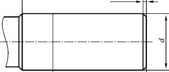
The design of spindles for drilling, drilling and milling, and some types of other machines has a groove for a cone foot to securely fix the cutting tool and prevent rotation. The through transverse hole is designed for installation in the wedge groove, and easy removal of the conical tool mandrel.
Basic dimensions of external instrumental metric and Morse tapers
| Cone name | N cone | Taper | D, mm | D1, mm | d1, mm | a, mm | Lmax, mm | lmax, mm | emax, mm |
| Metric | 4 | 1:20 | 4 | 4,1 | — | 2 | — | — | — |
| 6 | 1:20 | 6 | 6,2 | — | 3 | — | — | — | |
| Morse | 0 | 1:19,212 | 9,045 | 9,2 | 6,1 | 3 | 59,5 | 56,5 | 10,5 |
| 1 | 1:20,047 | 12,065 | 12,2 | 9 | 3,5 | 65,5 | 62 | 13,5 | |
| 2 | 1:20,020 | 17,780 | 18 | 14 | 5 | 80 | 75 | 16 | |
| 3 | 1:19,992 | 23,825 | 24,1 | 19,1 | 5 | 99 | 94 | 20 | |
| 4 | 1:19,254 | 31,267 | 31,6 | 24,5 | 6,5 | 124 | 117,5 | 24 | |
| 5 | 1:19,002 | 44,399 | 44,7 | 35,7 | 6,5 | 156 | 149,5 | 29 | |
| 6 | 1:19,180 | 63,348 | 63,8 | 51 | 8 | 218 | 210 | 40 | |
| Metric | 80 | 1:20 | 80 | 80,4 | 69 | 8 | 228 | 220 | 48 |
| 100 | 1:20 | 100 | 100,5 | 87 | 10 | 270 | 260 | 58 | |
| 120 | 1:20 | 120 | 120,6 | 105 | 12 | 312 | 300 | 68 | |
| 160 | 1:20 | 160 | 160,8 | 141 | 16 | 396 | 380 | 88 | |
| 200 | 1:20 | 200 | 201 | 177 | 20 | 480 | 460 | 108 | |
Diameters D1 and d1 are theoretically calculated and depend on the nominal dimensions D, a and l.
Basic dimensions of internal instrumental metric and Morse tapers
| Cone name | N cone | Taper | D, mm | g, mm | h, mm | l1, mm |
| Metric | 4 | 1:20 | 4 | 2,2 | 8 | 21 |
| 6 | 1:20 | 6 | 3,2 | 12 | 29 | |
| Morse | 0 | 1:19,212 | 9,045 | 3,9 | 15 | 49 |
| 1 | 1:20,047 | 12,065 | 5,2 | 19 | 52 | |
| 2 | 1:20,020 | 17,780 | 6,3 | 22 | 62 | |
| 3 | 1:19,992 | 23,825 | 7,9 | 27 | 78 | |
| 4 | 1:19,254 | 31,267 | 11,9 | 32 | 98 | |
| 5 | 1:19,002 | 44,399 | 15,9 | 38 | 125 | |
| 6 | 1:19,180 | 63,348 | 19 | 47 | 177 | |
| Metric | 80 | 1:20 | 80 | 26 | 52 | 186 |
| 100 | 1:20 | 100 | 32 | 60 | 220 | |
| 120 | 1:20 | 120 | 38 | 70 | 254 | |
| 160 | 1:20 | 160 | 50 | 90 | 321 | |
| 200 | 1:20 | 200 | 62 | 110 | 388 | |
Dimensions and elements of the Morse cone
The distinguishing feature of one Morse taper from another is its size. There are several types of them and, in accordance with GOST, each has a specific number and abbreviation. To measure it, you need to use a calibration, or best of all, a special table that will allow you to calculate dimensions down to the micron. Depending on the machine on which the part will be processed, you should choose, for example, a cutter, a drill, and then the type of invention of Stephen Morse.
With the development of the engineering industry, a need arose to expand the model range of Morse cones. For this purpose, a metric cone was developed, which did not have any special design differences from its predecessor. Its taper was 1:20, with an angle of 2°51'51″ and a slope of 1°25'56″. Metric tapers have made it possible to create a large selection of tools for various machines and operations. They are classified into two categories: large and small. Large ones are designated, for example, No. 120, 200, and the numbers correspond to the largest diameter of the metric cone.
Morse taper dimensions
A tool taper is a conical shank of some cutting tool and a conical hole in the spindle or headstock of the same diameter. Its function is to quickly change cutting tools and maintain high precision when centering and clamping.
It is used mainly in CNC machines because it eliminates a number of disadvantages of a conventional Morse taper.
Advantages:
- jamming of shanks in the spindle is much less;
- smaller sizes;
- improved axial stop;
- ease of fastening;
- automatic change of cutting tool.
Nowadays, Morse cones are manufactured in accordance with the international ISO and DIN standards. In Russia, the standardization system combines into one class both simple Morse cones, as well as metric and instrumental ones. Information about them can be obtained from GOST 25557-82. The situation with a single GOST has developed due to the fact that Morse cones have been very popular in our country since the times of the USSR, and in parallel with this, many new ones have appeared.
Download GOST 25557-82
Morse tapers are divided into 8 categories. Abroad these are MT0, MT1, MT2, MT3, MT4, MT5, MT6, MT7. In Germany, the numbering is the same, but the letter designation is MK. In our country and in the post-Soviet space KM0, KM1, KM2, KM3, KM4, KM5, KM6 and No. 80.
Short cone
As time has shown, some foreign-made Morse cones are inconvenient to use due to their large length. For this case, a series of shortened products has been developed, having 9 sizes.
Shortened Morse tapers
Due to the excess length of the Morse cone in some of its applications, a standard of shortened cones was formed. The cone designation contains the value of the largest diameter formed after decreasing the length while maintaining the ratio. Thus, nine standard sizes of shortened cones, B7, B10, B12, B16, B18, B22, B24, B32, B45, have become widespread when installing drill chucks and other tools.
The values of diameters D1 and d1 are theoretical and calculated and depend on the nominal dimensions D and L.
Main dimensions of shortened Morse tapers
| Cone name | N Morse taper | D, mm | D1, mm | d1, mm | amax, mm | L, mm | M | l1, mm |
| B7 | 0 | 7,067 | 7,2 | 6,5 | 3,0 | 11,0 | — | — |
| B10 | 1 | 10,094 | 10,3 | 9,4 | 3,5 | 14,5 | — | — |
| B12 | 1 | 12,065 | 12,2 | 11,1 | 3,5 | 18,5 | M6 | 16,0 |
| B16 | 2 | 15,733 | 16,0 | 14,5 | 5,0 | 24,0 | — | — |
| B18 | 2 | 17,780 | 18,0 | 16,2 | 5,0 | 32,0 | M10 | 24,0 |
| B22 | 3 | 21,793 | 22,0 | 19,8 | 5,0 | 40,5 | — | — |
| B24 | 3 | 23,825 | 24,1 | 21,3 | 5,0 | 50,5 | M12 | 28,0 |
| B32 | 4 | 31,267 | 31,6 | 28,6 | 6,5 | 51,0 | M16 | 32,0 |
| B45 | 5 | 44,399 | 44,7 | 41,0 | 6,5 | 64,5 | M20 | 40,0 |
Types of cones
Morse can be manufactured using different technologies, so it is not always possible to replace one tool with another without problems.
Before selecting a suitable fairing, you need to decide what dimensions the Morse cone has that correspond to GOST .
Tools often differ from each other in length, diameter, and angle.
When choosing a fairing, you need to pay attention to the letters and numbers:
- the number opposite the letter “D” means the basic size of the cone socket;
- the number next to “L” is the penetration depth.
These sizes are common to all countries where the metric number system is actively used. Morse fairings created today, as a rule, have adapters that can be changed. This simplifies the work, since the equipment can be combined with different standards.
Capital letters of the Latin alphabet indicate features of the flange section. The proluvium itself can have a length from 2.5 cm to 16 cm.
Today, the highest quality fairings for drilling machines can be considered tools that are produced under the brands “Kennametal” and “Kapto”.
Those who work on the machine know very well that they have good resistance to sudden and significant changes in temperature. The cones of these brands are quite durable and easy to use. They meet all the necessary requirements. Morse codes, which are marked "Capto", are released and distributed throughout the world.
Today, such instruments are promoted as high-end analogues of HSK. The fairing itself, when projected onto a plane, will have the shape of a triangle. There are indentations on its round edges. But it should be noted that such a tool has a rather high price, since its manufacturing process is very complex. In turn, Kapto are divided into several types , the most popular among which are those designated as “C3” and “C10”.
Initially, such a tool was created so that it could be used for clamping using the collet method.
There is a division into 8 sizes: the smallest of them is designated as “KM0”, and the largest is designated as “KM7”. All other types of cones are also designated by the letters “K”, “M” and a number from 1 to 6
. However, the Russian standard does not recommend using the KM7 Morse fairing; instead, a metric cone No. 80 is used.
Fairings that are designed to both inch and metric standards can be interchanged. They are similar in every way and differ only in the thread of the shank.
