General information about microarc oxidation of aluminum (MAO).
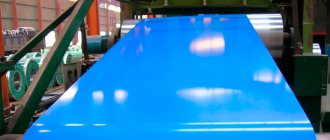
Today, one of the most popular structural materials is aluminum. It is distinguished at the same time by its lightness, strength, electrical and thermal conductivity, and corrosion resistance. Under the influence of atmospheric oxygen or other oxidizing agents, aluminum is easily passivated - a natural oxide film (Al2O3) 0.002-0.005 microns thick appears on its surface. The passive film significantly inhibits the corrosion processes on aluminum under atmospheric conditions, despite the fact that it itself is a very active metal.
Al2O3 is stable in neutral and slightly acidic solutions, has pronounced dielectric properties and is one of the hardest compounds in nature. The disadvantage of natural aluminum protection is the small thickness of the passive film. For this reason, it does not provide it with adequate resistance to either corrosion in aggressive environments or abrasion.
To improve these parameters, the thickness of the oxide film must be artificially increased. This process is called oxidation.
Oxidation of metals is, in principle, carried out by thermal, chemical, anodic and microarc methods.
For aluminum, the last three oxidation methods are used:
- Chemical oxidation is significantly inferior to anodic and microarc in terms of performance characteristics, but is the simplest and cheapest.
- Good results can be obtained with anodic oxidation (the most common method).
- The best coatings are obtained using MAO, but this is also the most expensive, complex and energy-intensive process.
MAO is a relatively new method for modifying the surface of aluminum. It was developed at the Institute of Inorganic Chemistry SB RAS in 1969 under the leadership of G.A. Markova. MAO allows the application of ultra-strong oxide coatings with unique protective, electrical insulating, and decorative properties. In appearance, the coating obtained by the microarc method is very similar to ceramics. The process is applicable not only to aluminum, but also to other valve group metals, such as Ti, Zr, Mg, Ta, Be.
MAO is performed in an electrolyte solution under current, just like anodizing, but differs from it by using a much higher voltage and high-density electric current. When such a current passes through the metal-electrolyte interface, chaotic microplasma discharges with high temperatures appear on the surface of the part, which outwardly looks like a luminous halo. These microdischarges have a plasma-chemical and thermal effect on the coating and electrolyte. At the discharge site, a film is formed from oxidized forms of the base metal and electrolyte components. It is possible to obtain coatings with different thicknesses, porosities and properties by selecting the desired oxidation mode and electrolyte composition.
Micro-arc oxidation - Modern restoration technologies
In recent years, scientists from RGAZU and OrelGAU have been conducting a lot of research in the development of the microarc oxidation (MAO) method, which is a type of plasma electrolytic anodic treatment (oxidation) method. Microarc oxidation is an environmentally friendly technology for the electroplasmochemical transformation of the surface layer of parts made of aluminum alloys into high-temperature modifications of aluminum oxides α and γ phases.
MAO allows you to create ceramic multifunctional coatings on the surface of a product, characterized by high wear resistance and adhesion strength, heat resistance and resistance to aggressive environments. The simplicity of technological equipment, environmentally friendly electrolytes, and the absence of special requirements for surface preparation before applying coatings predetermine the prospects of the MAO method for mechanical engineering, as well as for the restoration and strengthening of worn parts.
The technological installation (Fig. 17) for applying MAO coatings consists of a process current source (ITT) 6 and a process bath 1, communicating with a container 5 for cooling the electrolyte and a coil 4 with connecting hoses 3. Pump 2 serves to pump the electrolyte from one bath to another. Part 7 is placed in an electrolyte and secured to a current-carrying busbar.
Rice. 17. Installation diagram for micro-arc oxidation
When alternating current is passed from the ICT, microarc discharges appear on the surface of the workpiece. Low-temperature plasma is formed in the discharge channels and reactions occur during which the surface layer of the part is converted into high-temperature modifications of aluminum oxides α and γ phases with the inclusion of electrolyte components. In the local zone of oxide formation, the electrical resistance increases. Therefore, when the coating layer reaches a certain thickness, microarc discharges move to adjacent areas where the electrical resistance is lower. And this continues until the current decreases to a level at which the oxidation process stops. The result is coatings comparable in wear resistance to tungsten carbide.
Under the guidance of Doctors of Technical Sciences Batishchev A.N. and Kuznetsov Yu.A., employees of RGAZU and OrelGAU developed technologies for the restoration and strengthening of parts made of aluminum alloys AK7ch GOST 1583, AO3-7 GOST 14113, AD1 (1013), AMg2 (1520), D16 (1160) according to GOST 4784, as well as corrosion-resistant steel 12Х18Н10Т GOST 5632.
In Fig. Figure 18 presents a general block diagram of technologies for restoring and strengthening parts using MAO.
The parts are divided into groups according to the wear value, and a restoration and strengthening technology has been developed for each group.
Parts made of aluminum alloys are divided into three groups:
- Group 1 – parts with wear up to 0.06 mm;
- Group 2 – parts with wear from 0.06 to 3.0 mm;
- Group 3 – parts with wear exceeding 3.0 mm.
For parts of the first group, the MAO technology for restoring and strengthening parts is recommended. The technology includes preparatory processing (cleaning and defect detection of parts, preliminary machining, degreasing, insulation of places not subject to extension and installation of parts on the suspension), extension (MAO) and processing of parts after extension (dismantling from the suspension, removal of insulation, washing with water, drying and coating control, finishing machining of coatings and control). To build up parts from AK7ch and AO3-7, use an electrolyte of composition No. 1 containing KOH - 1.8...2.1 g/l, Na2SiO3 - 14...18 g/l. The current density is 25…30 A/dm2. Processing time 100…110 min. The coating thickness reaches 0.115 mm, and the microhardness is 8 GPa.
It is recommended to restore parts of the second group using three combined technologies: boring to repair size followed by hardening with MAO, plastic deformation with subsequent hardening of MAO, or supersonic gas dynamic spraying (GDS) with 254
Rice. 18. General block diagram of technologies for restoring and strengthening parts using MAO
subsequent strengthening of MAO. The first combined technology uses the same modes and electrolyte composition No. 1 specified in the previous technology.
To strengthen deformable alloys in the second combined technology, an electrolyte of composition No. 2 is recommended, which includes KOH - 4...6 g/l, H3BO3 - 20...25 g/l, starch - 6...12 g/l. The addition of starch increases the performance of the electrolyte up to 2 times. Hardening of MAO is carried out at an electrolyte temperature of 20...40 °C, a current density of 15...20 A/m2 and a treatment duration of 100...120 minutes. The thickness of the hardened layer reaches 0.15 mm, and the microhardness is 19 GPA.
Supersonic HDN is produced at an air pressure of 0.7 MPa, a temperature of 400 °C and a spraying distance of 10...15 mm. For spraying, aluminum-based powder A-80-13 is used, with a fraction of 30...50 microns. MAO processing is carried out at a current density of 18...22 A/dm2 with an oxidation duration of 100...120 minutes. The electrolyte of composition No. 3 includes KOH - 2.9...3.6 g/l, Na2SiO3 - 4...6 g/l. The thickness of the hardened layer reaches 0.135 mm, and the microhardness is 16 GPA.
For parts of the third group, it is recommended to install an additional repair part made of aluminum, strengthened with MAO. For strengthening, an electrolyte of composition No. 1 is used.
The wear rate of coatings obtained by MAO on aluminum alloys and sprayed surfaces is 4...6 times lower than the wear rate of unstrengthened parts.
Parts made of corrosion-resistant steels are also divided into three groups:
- group – parts operating under low contact loads, with wear up to 0.6 mm;
- group - parts operating under small and medium contact loads, with wear from 0.6 to 3.0 mm;
- group – parts with wear exceeding 3.0 mm.
For parts of the first group, a combined restoration and strengthening technology is recommended - gas flame spraying (GSP) with subsequent hardening by MAO. Spraying is carried out with powder gas-flame burners: “Iskra-1” and “Iskra-1B”. Initially, an underlayer is sprayed with PT-Yu5N powder with a thickness of 0.1...0.2 mm, then the main layer is made of SAS aluminum powder with a thickness of 0.15...0.3 mm.
The adhesion of the main sprayed layer depends on the powder fraction and the roughness of the sublayer (Fig. 19 and Fig. 20). As can be seen from Fig. 19 and 10.20, the optimal powder fractions D are in the range of 60...100 µm, and the surface roughness of the sublayer Rz is 60...120 µm. Hardening of MAO is carried out using an electrolyte of composition No. 2, while the thickness of the strengthened layer reaches 0.125 mm, and the microhardness is 11 GPA.
It is recommended to restore parts of the second group using a combined technology - supersonic gas-dynamic spraying (GDS) with subsequent hardening by MAO. The modes of HDN and MDO are the same as when restoring aluminum parts of the second group.
Rice. 19. The influence of the aluminum powder fraction on the adhesion of SAS-2 aluminum to the PT-Yu5N sublayer : 1 – upon tearing off; 2 – with shift
Rice. 20. The influence of the roughness of the PT-Yu5N sublayer on the adhesion to SAS-2 aluminum : 1 – upon tearing off; 2 – with shift
For parts of the third group, it is recommended to install an additional aluminum repair part, strengthened with MAO. For strengthening, an electrolyte of composition No. 1 is used. The corrosion resistance of coatings treated with MAO increases by 1.4...1.6 times, and wear resistance by up to 5 times, in comparison with the same characteristics of steel 12Х18Н10Т.
The experience of restoring gear pumps NSh-32U-3 and NSh-10E, pumps 50-3Ц7.1-20, hydraulic coupling pistons of the Fendt Favorit 824 tractor, shafts of the SPO-35-89 stand for laying metal cord of auto-tractor tires has shown the high efficiency of the developed technologies.
Currently, the most widely used method in the repair industry is the formation of MAO coatings. When restoring large-sized parts using this method, there is a need to significantly increase the overall dimensions of the baths, and the costs of preparing, monitoring and adjusting the electrolyte, which in this case is required an order of magnitude more, significantly increase. Due to the fact that, as a rule, not the entire part is restored, but only the worn surfaces, the surface area subject to insulation increases significantly. For the above reasons, the cost of restoration increases significantly.
In this regard, flow oxidation seems promising when restoring large MAO parts. The essence of the method is that, with the help of simple devices, the restored surfaces become the walls of an electrolytic cell through which the electrolyte is pumped with an alkali-resistant pump. In this case, local restoration and strengthening of the surfaces of parts of almost any overall dimensions is possible, which differs in comparison with the bath method by a significant reduction in energy consumption. Thanks to the intensive renewal of the electrolyte and the removal of gaseous products from the anode-cathode space, a more optimal structure of MAO coatings and a reduction in residual stresses in them are achieved.
MDO was further developed in the works of Doctor of Technical Sciences, Professor A. V. Kolomeichenko and his students. An installation design has been developed for flow-through MAO of internal cylindrical surfaces of one-piece sliding bearings with electrolyte cooling, the schematic diagram of which is shown in Fig. 21.
During its operation, the alkali-resistant pump 11 pumps electrolyte from tank 9 and forces it through pipeline 12, cooler 13 and supply pipe 14 into the internal cavity of the electrolytic cell 6. The latter contains the oxidized part 1 and the electrode 7 in the form of a stainless steel cylinder, which through the ring 2 is attached to plate 3 using a bolt 4 and nut 5. At the same time, through the inlet pipe 15, a cooling agent is supplied to the cooling section of the cooler 13, which, after filling the section, is discharged through the outlet pipe 16. When the oxidized part 1 is completely covered with electrolyte, the latter through the outlet pipe 8 enters the tank 9 and at the same time the power supply is turned on.
The higher the current density, the more intense the process. However, with increasing current flowing through the electrolyte, the latter becomes very hot.
It partially evaporates, overheats the insulation of the conductors and suspension, and at a certain point in time, the growth of the hardened coating layer begins to slow down. This is due to the fact that at high temperatures the electrolyte begins to partially dissolve the forming MAO coating, which leads to a decrease in its thickness and the formation of additional porosity.
Rice. 21. Installation for flow-through MAO of parts with electrolyte cooling
In addition, the passivation of the oxidized surface is reduced, due to which electrical breakdown occurs at lower voltage values and this, in turn, causes a decrease in the content of the high-temperature strengthening phase α-Al2O3 in the strengthened layer. Therefore, to carry out the process at a high current density, it is necessary to cool the electrolyte. The most effective method of cooling the part on the surface of which an MAO coating is formed is the internal cooling method. However, its implementation is difficult, since in addition to passing electric current through the part, it is necessary to supply and remove a cooling agent, which must circulate inside the part and not mix with the electrolyte during oxidation.
There is a simpler method of cooling the part - the external cooling method. When using it, the part is cooled directly by the electrolyte, which must have a constant temperature, varying within insignificant limits. To do this, a cooler is built into the circulation circuit of the flow-through unit, in which the electrolyte gives off its heat to the cooling agent (cold water, freon or R134A refrigerant).
Thanks to the continuous cooling of the electrolyte during its flow circulation through the pumping system of the installation, the temperature of the electrolyte is maintained in the range of 8...10 °C, therefore the formation of MAO coatings can be carried out at a higher current density, which increases their thickness and improves the physical and mechanical properties (Table. 2).
Table. 2 Properties of coatings obtained by flow-through MAO
| Index | Meaning | |
| without electrolyte cooling | with electrolyte cooling | |
| Coating thickness, microns: hardened layer loose layer | 100 70 30 | 130 115 15 |
| Microhardness, GPa | 9,6 | 11,0 |
| Porosity, % | 25…35 | 14…18 |
| Wear rate, (g/h)x10-3 | 156 | 115 |
| Corrosion resistance,% | 100 | 150 |
As can be seen from table. 2, the use of flow-through MAO parts with electrolyte cooling makes it possible to increase the thickness and corrosion resistance of the strengthened MAO coating layer by up to 50%, as well as its microhardness by 15%. At the same time, porosity and wear rate are reduced.
The greatest productivity is achieved when, during oxidation, a turbulent flow regime of the electrolyte is created, which is achieved at a flow speed of more than 1 m/s.
Microarc oxidation in a flow electrolyte has the following advantages:
- intensive mixing of the electrolyte and replenishment of it with new enriched portions leads to improved physical and mechanical properties and improved quality of coatings;
- the constant supply of fresh electrolyte and bubbling with compressed air the combustion zone of microarc discharges leads to the initiation of the latter, thereby increasing the oxidation productivity;
- the saturation of the coating and the substrate material with hydrogen released during oxidation decreases;
- the service life of the electrolyte increases and, accordingly, the time intervals between its replacements;
- the amount of electrolyte used is significantly reduced, which reduces the cost of recovery;
- The process of forming strengthening coatings is highly stable, which makes it possible to recommend the method in mass production for obtaining coatings with specified properties.
The mechanism of formation of coatings using the MAO method assumes the presence of through porosity in them, which determines the protective properties of coatings when working in contact with aggressive environments. With boundary friction in coatings formed by MAO, under certain operating conditions, an increase in friction properties may occur. This leads to the fact that a part coated with MAO causes increased wear of the mating part, acting on it as an abrasive.
The problem of increasing the corrosion resistance of MAO coatings was solved by optimizing MAO modes that ensure a reduction in the through porosity of the coating. To increase the wear resistance of the working surfaces of machine parts, it is proposed to fill the coating formed by MAO with oil or apply a copper layer to it using an original friction-mechanical method.
The rubbing copper plate 1 is pressed with a force Fп to the MAO coating 4 and moves relative to it with a speed Vск (Fig. 22).
Rice. 22 – Scheme of interaction of a rubbing plate with a coating formed by MAO during frictional-mechanical application of a copper layer : 1 – rubbing plate made of copper; 2 – heat-insulating oxide coating formed by MAO; 3 – pressure element of the device for rubbing; 4 – coating formed by MAO; 5 – detail
A plate made of technically pure copper of grade M2 is fixed on the pressure element of the rubbing device 4. An oxide coating 2 is placed between them. Since the copper plate is in contact on both sides with ceramic (oxide) coatings, it has limited heat dissipation to the environment. Therefore, when the plate moves, its temperature rises to a value at which it recrystallizes and is transferred to the coating surface to form a continuous copper layer.
Research has established the optimal parameters of MAO: concentration of electrolyte components, g/l: KOH -3, Na2SiO3 – 10, the rest is distilled water; MDO modes: current density – 20 A/dm2, electrolyte temperature – 200C, MDO duration – 2 hours. Optimization of the electrolyte composition and MAO modes made it possible to reduce the through porosity of the coatings from 14...15 to 3...4%.
The optimal modes of frictional-mechanical application of a copper layer on the surface of a coating formed by MAO have been determined: contact pressure - 15 MPa, sliding speed - 0.5 m/s, rubbing plate thickness - 0.05....0.10 mm, application duration - 230... .240 s, lubricant of contacting surfaces - technical glycerin, which allows you to obtain a copper layer with a thickness of 4.0...4.5 microns and a roughness Ra = 0.63 microns.
In Fig. 23. Shows the results of a study of the load capacity of various versions of MAO coatings. It follows from the figure that filling an MAO coating with a porosity of 14...15% with spindle oil with spindle oil increases the load capacity of the movable steel-coating joint by 1.8 times, and the friction-mechanical application of a copper layer on its surface by 2.8 times. Further studies showed that when a MAO coating with a porosity of 14...15% is filled with oil, the wear resistance of the movable joint “steel - coating” increases by 1.7 times, and when a copper layer with a porosity of 3...4% is applied to its surface - by 4.5 times.
As a result of summarizing the research results, Orel State Agrarian University scientists have developed combined restoration and strengthening technologies, which are shown in Fig. 24.
Rice. 23. Load capacity for steel-coating joints formed by MAO : porosity 3...4%" (1), porosity 14...15%" (2), porosity 14...15% filled with oil" (3), porosity 3... 4% with copper layer" (4)
Combined technologies include surfacing, soldering, electric arc metallization, crimping, production of an additional repair or new part, followed by the application of a ceramic coating by microarc oxidation. Depending on wear, area of damage, size and material of parts, as well as the availability of repair and technological equipment at a particular enterprise, restoration or production of new (repair) products is recommended to be carried out along one of the routes presented in the figure. The thickness of the strengthened layer after removing the technological layer is: on the deformed alloy D16 – 150 microns; on casting alloys AK7ch and AK9ch, on casting alloys AK7ch and special AO3-7 after compression, on PA12 solder and on welding wires SvAMr6, SvAK5, SvAK9M2 - 120 microns, and its through porosity will be no more than 4%. The optimal coating roughness for applying a copper layer is Ra = 1.20...1.25 µm.
Rice. 24. Block diagram of combined technologies for restoring worn-out parts and manufacturing new (repair) parts with MAO hardening to increase the durability of working surfaces of machine parts
Composition of electrolytes for MDO.
The composition of the electrolyte during MAO, along with the substrate material, treatment mode and time, is a determining factor in the process.
Electrolytes used for MDO are:
- not having components that form insoluble oxides: solutions of sulfuric, phosphoric acid, alkali. The coatings formed in such electrolytes penetrate deeper into the metal due to its oxidation.
- which contain cations or anions that form insoluble oxides and hydrolysis products: aluminate and silicate-alkaline solutions, as well as solutions containing soluble phosphates, bicarbonates and molybdates). After thermolysis, these electrolyte components in the discharge zone become part of the coating and provide an additional increase in the size of the part after the formation of the oxide layer.
The applied MDO modes differ in:
- type of current (direct current, alternating current, alternating current superimposed on direct current);
- polarity of the applied voltage;
- changes in electrical parameters (galvanostatic, galvanodynamic, potentiostatic, potentiodynamic, constant or falling power modes);
- the nature of the discharge (spark, microarc, arc, arc electrophoresis);
- degrees of control (manual, semi-automatic, automatic).
The voltage on the bath is 600-1000 V, the current density is up to 30 A/dm2, the specific power consumption reaches 11000-30000 W/dm2. For comparison, when anodizing, the output voltage is in the range of 12-180 V (higher values are used extremely rarely), current density is 0.5-2 A/dm2, specific power consumption is only 6-360 W/dm2. Chemical oxidation is carried out without any current at all.
No special surface preparation is required before applying the coating.
In practice, the microarc oxidation process is carried out mainly in weakly alkaline electrolytes when pulsed or alternating current is supplied.
Microarc oxidation technology (MAO coating) and coatings based on it
Micro-arc oxidation technology, in terms of technological advantages, allows you to obtain coatings with a wide range of applications and apply coatings both to new products and to restore coatings after wear, reduces coating application time, allows you to use less equipment, less production space and saves water consumption . The microarc oxidation method makes it possible to form coatings that have a variety of functional properties, such as corrosion-resistant, wear-resistant, heat-resistant, electrical insulating, protective and protective-decorative. Such multifunctionality of coatings allows them to be used in a wide variety of industries.
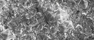
Structure and composition of the oxide coating during MAO.
Anodic microarc discharges pass between the surface of the oxide film and the electrolyte, heating the film to high temperatures of 1000-2000 °C. At such temperatures, thermal destruction of water occurs with the formation of atomic and ionized oxygen. High-temperature phases are formed in the coating (corundum α-Al2O3), decomposition of the electrolyte components and their interaction with the base metal oxides occurs. MAO coating, therefore, is not purely oxide, but has a complex composition and structure.
The resulting oxide layer is approximately 70% formed deep into the base metal and only 30% of the coating extends beyond the original dimensions of the part.
The metal-oxide-discharge-electrolyte system realized during MAO has ionic conductivity, and the current flows through the discharge channels. Therefore, the formation of pores in the coating is a prerequisite for its formation.
MAO coating has a layered structure, an example of which is shown in Figure 1:
- The outer layer (technological) is loose. When using an alkaline electrolyte with the addition of liquid glass, this layer consists of mullite Al2O3*2SiO2
- The inner layer is dense and has high microhardness. Consists of aluminum oxide Al2O3.
- The transition layer is thin, from 0.01 - 0.1 microns, located between the substrate material and the oxide layer.
The top loose layer is often removed by sandblasting and the part with a dense oxide coating is put into service.
Figure 1 - Layer-by-layer structure of the coating obtained by the MAO method: 1 - outer (technological) layer, 2 - dense (working) layer: 3 - transition layer: 4 - base material.
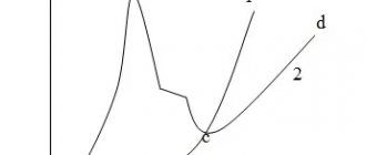
The composition of the coating depends on the processing time. An example is shown in Figure 2.
Figure 2 - Change in the content of aluminum and phosphorus on the surface of the MAO coating depending on the time of treatment in the phosphate electrolyte.