Application of pitch thread
Modular and pitch threads are used on units where it is necessary to ensure motion transmission. These are worm and worm-gear gears, which are used:
- in mechanical jacks;
- press;
- lifts;
- extruders.
This type of thread ensures reliable engagement of the gear teeth with the worm. A similar result can be achieved by setting the pitch profile to 40 degrees (for comparison, for a metric thread it is 60 degrees).
Pitch carving: what is it, photo
First of all, you need to understand what modular and pitch threads are.
Modular threads are measured by module. Therefore, to obtain a value in the metric system of units, you must multiply the value by the modulus.
Pitch threads are measured in pitches. Therefore, to obtain a clear inch value, you need to divide the value by pitch. These types of threaded connections are used when cutting the worm of a worm gear.
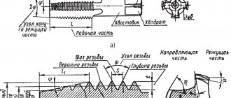
Basic parameters of pitch thread
The parameters that determine the characteristics of a pitch thread include:
- coil profile (geometry and angle of inclination);
- pitch pitch (distance between points of the same name);
- dimensions of the middle, inner and outer circles;
- thread stroke and cut.
Each of these parameters has its own notation systems. The main one is the step unit. The pitch system involves the use of pitches. In this case, the thread pitch equal to 2 pitches corresponds to 6.28 dm. To systematize existing pitch thread sizes and bring them to familiar units of measurement, special tables are used.
Size correspondence table for metric, inch, modular and pitch threads
Both modular and pitch threads are classified according to the thread profile. They are:
- in the shape of an Archimedean spiral;
- in the form of an involute (that is, a second-order curve, each point of which serves as a tangent to a given circle);
- trapezoidal shape.
The size of the threads depends on the application of the thread. Each diameter is defined as the diameter of an imaginary cylinder. Thus, the average diameter is determined for a cylinder, the radius of which represents half the distance from the top to the bottom point of the thread. You can measure the main parameters with a caliper or other measuring instrument.
Types of metric threads
Metric threads also mean all types with different profiles, measured in millimeters. These include:
- triangular thread;
- trapezoidal;
- rectangular;
- round.
In addition to the metric system for measuring parameters, the following are used:
- inch;
- modular, where the module is the ratio of the length, expressed in millimeters, to the number π;
- pitch, basic unit - pitch - the ratio of the number π to the length, expressed in inches.
Modular threads are used for worm gears in mechanical engineering, just like pitch threads. Inch and metric are fastening thread types, but can be used for transmission.
By location they are distinguished:
- internal;
- external
The internal thread is located in the hole, it is obtained with a tap, a specialized tool that is a rod with cutting edges.
Internal metric thread
External threads are made with a cutter or die on a rod. They can also be obtained by coasting on appropriate equipment.
External metric thread
The shape of the surface can be cylindrical or conical.
Metric conical thread is used for installation of pipelines. It is performed on surfaces where the larger diameter exceeds the small one by 16 times. Diameters vary from 6 to 60 mm.
They are also divided according to the direction of the turns into right and left. To determine the direction of the thread, it is necessary to position the part so that its axis is located away from the observer. Then, the right-hand thread is formed by a circle rotating from left to right with translational motion along the axis, and the left-hand thread, accordingly, counterclockwise.
There are different types of step sizes:
- large (with a main, large step);
- small (with small);
- special.
A large pitch is considered normal and is suitable for any materials, including fragile ones. Small allows you to withstand heavy loads, but the materials must have certain strength characteristics. Small and special ones are rarely used.
Large and fine thread pitch
The place of transition from a smooth surface to a helical one is called the approach. Based on their number, they are divided into: single- and multi-pass. The latter are also subdivided by the number of passes: two-, three- and multi-pass.
Another classification is by application. They are:
- fastening and thrust-fastening;
- kinematic or chassis;
- special purpose.
Below are the main types of metric threads and their letter designations:
- the capital letter "M" symbolizes the metric type,
- if it is made on the surface in the form of a cone, then “MK”;
- for conditions where heat resistance and strength are required, use the metric cylindrical “MJ”;
- according to ISO – “EG-M”;
- trapezoidal – “Tr”;
- persistent with an angle of inclination of one side of 30º – “S”;
- persistent reinforced - “S45”, where the number is the angle of inclination of one of the sides.
Pitch thread cutting technology
Pitch threads of different sizes are cut:
- cutters on screw-cutting lathes;
- modular cutters on milling machines;
- finger cutters.
Thread cutting on a lathe allows you to achieve high precision results, but does not guarantee sufficient productivity. In this way, pitch threads are cut on worm shafts, which must be characterized by high accuracy of motion transmission. The method is used in small-scale production and in private workshops.
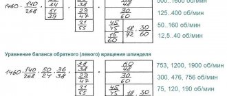
Using a milling machine allows you to achieve higher productivity when cutting threads. The cutter is installed so that its axis of rotation intersects the longitudinal axis of the workpiece shaft at an angle of 90 degrees. To improve the quality of the notch, it is cut in several passes. Before starting work, the milling machine is set up according to the data from the tables, which give the dimensions of the pitch threads. These parameters allow you to install the required set of gears on a screw-cut guitar with specified gear ratios.
Finger cutters are suitable for cutting pitch threads on large items. To apply a pitch notch, special milling heads with an individual cutter drive are installed on the machine. The first pass is performed with a slotted finger cutter of a straight-through profile, with a profile angle of 35 degrees.
Size chart for cutting pitch threads on a machine
Connection parameters
The minimum pipe thread diameter is 1/16″, which corresponds to 7.72 mm, the maximum is 6″ or 163.8 mm. There are 16 standard sizes in total, depending on the outer diameter of the connection, which is measured along the upper ridges. The internal diameter is determined by the lowest points at the opposite ends of the ridge.
Another leading characteristic is the cutting pitch, which is determined by the distance between adjacent thread crests or valleys. The pitch is the same on any section of the connection and is measured by the number of turns per technical inch equal to 25.4 mm. This characteristic also depends on the profile height and is equal to half the difference between the internal and external diameters.
Basic rules for designating pitch threads
Designations in connections with pitch threads are indicated in GOST standards. Each of them contains the following elements:
- a letter indicating that the thread belongs to a certain type;
- size in pitches;
- thread pitch size;
- direction (left - L or right - RH);
- tolerance field dimensions;
- make-up length.
The value of the tolerance field is indicated by several letters and numbers. The former indicate the size of the deviation, the latter indicate the accuracy class. In the first place are symbols characterizing the average diameter, in the second place are symbols relating to the outer diameter. If the dimensions match, only one designation is applied. To indicate the make-up length, three Latin letters are used, with the letter N corresponding to normal length, S to short, L to long.
The rules for applying symbols indicating the main dimensions and other characteristics of pitch threads are given in the form of tables in GOST 24705-2004 and GOST 16093. In 2005, additions were made to the text by adding the main provisions of the ISO 965-1 and ISO 965-3 standards. The pitch system is used in North American countries, and its characteristics are specified in the international standard ANSIB1.9.
Connection parameters
The minimum pipe thread diameter is 1/16″, which corresponds to 7.72 mm, the maximum is 6″ or 163.8 mm. There are 16 standard sizes in total, depending on the outer diameter of the connection, which is measured along the upper ridges. The internal diameter is determined by the lowest points at the opposite ends of the ridge.
Another leading characteristic is the cutting pitch, which is determined by the distance between adjacent thread crests or valleys. The pitch is the same on any section of the connection and is measured by the number of turns per technical inch equal to 25.4 mm. This characteristic also depends on the profile height and is equal to half the difference between the internal and external diameters.
Decoding the writing of threads
Graphic materials are designed in accordance with the instructions of GOST 2.311-68 “Image of threads”.
A typical designation structure contains:
- the literal part defining the type;
- numbers corresponding to the nominal size in millimeters or inches;
- pitch (mm) is indicated only as fine, after the “×” sign;
- for multi-start ones, instead of the previous paragraph, the stroke (mm) is given, then the step in parentheses;
- direction: right is the default, left is LH;
- tolerance range or accuracy class;
- make-up length other than normal.
Example 1: М16×1.5LH–6H. Explanation:
- M – metric cylindrical;
- 16 – nominal diameter, mm;
- 1.5 – fine pitch, mm;
- LH – left;
- 6Н – tolerance range, where 6 – degree of accuracy; H – main deviation. Capital letters are used for internal (nuts), hence the threads in the hole.
The screw-in length is not indicated, which means it is normal.
- G – cylindrical pipe;
- 1/2 – thread size, inches; corresponds to the internal diameter of the pipe;
- A – accuracy class.
The designation options are illustrated below.
Geometric parameters
The parameters determine the purpose of geometric metric cutting for joining materials. Basic designations:
- The nominal diameter of the thread is designated by the letter D. The internal type of fastener is defined as d, external with a capital letter.
- Depending on the location, there is a definition of the average thread diameter. Identified by letters and numbers, for example D2.
- In the drawings there is a thread parameter, such as the internal diameter, the designation is made by the number 1, for example d
- To calculate the mates in the connection structure, the inner circumference of the product is used.
- Determining the distance between the top points of closely spaced threads is called the thread pitch. To distinguish parts with a repeating diameter in the presented drawing, a division into a main step and a step with smaller geometric parameters is used, the designation is set to the letter P.
- The thread stroke and its parameters correspond to the movement of the linear value of the screw fastening connection per full revolution, as well as the distance between the peaks and valleys formed on the surface.
- The height of the triangle forms the dimensions, connection parameters, profile, and the letter H is used for the designation.
Table of metric thread sizes
Parameters such as the average thread diameter must be presented using the accompanying documentation. For standardized display, GOST standards are used. The standards stipulate the display of the main dimensions of connecting products and parameters; GOST 24705-2004 applies to all types of threaded connections.
Metric cuttings of connections are used in the manufacture of objects by applying parameters to drawings. Thread sizes are described in the table, with nominal diameters ranging from 1 to 600 millimeters. The pitch is determined in the table from 0.25 to 6 mm, symbol when displayed through “x”, for example M8 × 1.5.
To produce internal cutting, tools are used (cutters, taps, sliding taps, group cutters, knurling rollers) produced at serial tool factories. The production of special cutting tools is carried out in the tool shops of large production associations.
The most common method is cutting using taps. Threads can be cut manually and on various types of machines. In mass production, automatic machines are used for cutting nuts; an example of such equipment is the MH 63 machine. It is used for cutting threads from M12 to M20 with different pitches. Taps with a curved shank are used as cutting tools. The power of the installed engine allows processing both non-ferrous metals and high-alloy steels.
In conditions of mass production of nuts, so-called automatic knurling machines are used. They are designed in such a way that they allow cutting on nuts of different sizes from M5 to M60 with different productivity, from several to tens of pieces per minute, and purposes, for example, intended for fixing anchors.
For cutting in body parts, multi-spindle units are used, which allow processing several holes at once. Such equipment is used in the processing of propulsion systems for automobile and tractor equipment.
Cutting internal threads is a rather difficult process, during which both the tool and the workpiece experience severe stress, leading to an increase in temperature. For this purpose, lubricating and cooling liquids (coolants) are used.
For manual production, castor oil is used, for example.
Trapezoidal threads Tr
In running gears, a trapezoidal metric thread with the designation Tr is used to convert rotational motion into translational motion. This type is applied to screws that are functional components of machine tools, lifts and other mechanical equipment. The Tr standard includes right-handed and left-handed, single-start and multi-start threads. The diameter is 10-640 mm. Trapezoidal threads, the parameters of which are regulated by GOST 9481–81, are designed for heavy loads.
Geometric parameters
The parameters determine the purpose of geometric metric cutting for joining materials. Basic designations:
- The nominal diameter of the thread is designated by the letter D. The internal type of fastener is defined as d, external with a capital letter.
- Depending on the location, there is a definition of the average thread diameter. Identified by letters and numbers, for example D2.
- In the drawings there is a thread parameter, such as the internal diameter, the designation is made by the number 1, for example d
- To calculate the mates in the connection structure, the inner circumference of the product is used.
- Determining the distance between the top points of closely spaced threads is called the thread pitch. To distinguish parts with a repeating diameter in the presented drawing, a division into a main step and a step with smaller geometric parameters is used, the designation is set to the letter P.
- The thread stroke and its parameters correspond to the movement of the linear value of the screw fastening connection per full revolution, as well as the distance between the peaks and valleys formed on the surface.
- The height of the triangle forms the dimensions, connection parameters, profile, and the letter H is used for the designation.
Table of metric thread sizes Parameters such as the average thread diameter must be presented using the accompanying documentation.
GOST standards are used for standardized display. The standards stipulate the display of the main dimensions of connecting products and parameters; GOST 24705-2004 applies to all types of threaded connections. Metric cuttings of connections are used in the manufacture of objects by plotting parameters on drawings. Thread sizes are described in the table, with nominal diameters ranging from 1 to 600 millimeters. The pitch is determined in the table from 0.25 to 6 mm, symbol when displayed through “x”, for example M8 × 1.5.
To produce internal cutting, tools are used (cutters, taps, sliding taps, group cutters, knurling rollers) produced at serial tool factories. The production of special cutting tools is carried out in the tool shops of large production associations.
The most common method is cutting using taps. Threads can be cut manually and on various types of machines. In mass production, automatic machines are used for cutting nuts; an example of such equipment is the MH 63 machine. It is used for cutting threads from M12 to M20 with different pitches. Taps with a curved shank are used as cutting tools. The power of the installed engine allows processing both non-ferrous metals and high-alloy steels.
In conditions of mass production of nuts, so-called automatic knurling machines are used. They are designed in such a way that they allow cutting on nuts of different sizes from M5 to M60 with different productivity, from several to tens of pieces per minute, and purposes, for example, intended for fixing anchors.
For cutting in body parts, multi-spindle units are used, which allow processing several holes at once. Such equipment is used in the processing of propulsion systems for automobile and tractor equipment.
Cutting internal threads is a rather difficult process, during which both the tool and the workpiece experience severe stress, leading to an increase in temperature. For this purpose, lubricating and cooling liquids (coolants) are used.
For manual production, castor oil is used, for example.
Supply of thread-cutting equipment
LLC "Russian-Metal" will provide the needs of any enterprise for professional equipment. If you are interested in wholesale supplies of tools for high-quality carving of a certain type, please contact us. A rich assortment, unlimited volumes, prompt shipment, minimum prices and maximum security of transactions are our advantages. Large orders for objects in the capital and the Moscow region are delivered free of charge. Buy thread-cutting equipment wholesale on favorable terms!
Implementation of a system of standards in Russia
The Congress, held in Zurich at the end of the 19th century, became a significant event for the standardization of carvings in Europe. But in Russia, the beginning of the process was delayed until 1921, when, on the initiative of the People's Commissariat of Railways, the first standards were developed specifically for railway transport. The NKPS-1 tabular system, based on German metric thread standards, included sizes 6-68 mm. It turned out to be the basis for the creation of OST 32 in 1927, followed immediately by OST 33A. It is based on the Whitworth system.
The development of USSR state standards did not stop there. Modernization of Acme standards issued in the United States led to the standardization of trapezoidal threads in 1932. The abbreviation GOST for national systems was adopted eight years later. In 1947, ISO thread standards appeared, which are still used today. Since then, Russia has taken into account both state and international standards, according to which domestic products for threaded connections are produced at the world level of quality.
Natural analogue of thread
Technogenic civilization began to develop thanks to successful solutions copied from the creations of nature. It’s easy to count the exceptions on one hand, and in 2011 there were one fewer exceptions. It was then that the discovery was made about the existence of threaded connections in the structure of living beings. Trigonopterus oblongus is a weevil beetle native to New Guinea. Researchers from Germany's oldest university, Karlsruhe, have discovered that the insect's leg joints are connected by threads rather than hinges like other species.
Important point. In fact, nature has many original ideas, each of which could serve as the first impetus for the invention of carving. Spiral geometry is inherent in the shells of a number of marine inhabitants and epiphytic plants entwining tree trunks, and the method of screwing into the ground is often used by living creatures of various levels to protect themselves from natural enemies or search for food.
An article about the results of the study was published in the most authoritative US periodical, Science. Although it has now been scientifically proven that the primary invention of the threaded connection does not belong to humanity, you should not be disappointed in your own achievements. After all, analogues of wheel and gear mechanisms have not yet been found in nature. Since the introduction of primitive mechanics into mass production, our civilization has stepped far forward, but carving is still relevant, and tools for its application are always in demand.
Pipe cylindrical, pipe conical and conical inch
Pipe cylindrical threads have found their application in the construction of pipelines. Manufacturers produce products with threads ranging from 1/16 to 6 inches. At the same time, up to 28 to 11 threads of thread can be applied per inch.
Pipe tapered thread
This type of material is used as a fastening and sealing material. The requirements for it are defined in GOST 6211-81. This document states that the profile must correspond to the inch profile. It is made on a cone with an angle of 1:16.
The base has an angle of 55⁰.
It ensures the tightness of the connection without the use of any additional devices (washers, sealants, etc.). Using this type of connection dramatically reduces the time required to assemble/disassemble the connection. It can be found in supply systems for oil, fuel, steam, etc.
Inch tapered thread
It is most often used to connect elements included in fuel, oil and other pipelines. Not so long ago, it was standardized based on the inch system of measures.
Inch conical die
The base is a triangle with an angle of 60⁰. But, in recent years, in practice they have begun to more often use a conical profile made on the basis of the metric system of measures.
Round threads Kr
According to GOST 13536-68, threads are applied to pipeline fittings of engineering systems for supplying drinking water or technical liquids, including aggressive media. The Kr marking applies to valve and spindle mechanisms, mixers and other sanitary equipment components for water supply systems. This is a round thread with a profile formed by arcs in the valleys and at the tops, which are connected to the corner by straight lines. Despite the limited scope of operation, the standard is in demand due to the prevalence of products.