Information about the manufacturer of the screw-cutting lathe 16K20
Manufacturer of the screw-cutting lathe 16K20 - Moscow Machine Tools named after. A.I. Efremova , founded in 1857.
The first universal screw-cutting lathes with a gearbox for the first time in the USSR began to be produced at the Moscow Machine Tool Building named after. A.I. Efremov in 1932 and received the names DIP-200, DIP-300, DIP-400, DIP-500 ( DIP
- Catch up and Overtake), where 200, 300, 400, 500 is the height of the centers above the frame.
Machine tools produced by the Moscow Machine Tool Plant Krasny Proletary, KP
- 1A62
- universal screw-cutting lathe, Ø 400 - 1K62
- universal screw-cutting lathe, Ø 400 - 1K62B
– high-precision universal screw-cutting lathe, Ø 400 - 1K282
- eight-spindle vertical lathe, Ø 250 - 1K620
- universal screw-cutting lathe with variator, Ø 400 - 1K625
- lightweight screw-cutting lathe with an increased line of centers, Ø 500 - 16A20F3
– CNC lathe, Ø 400 - 16B20P
- high-precision screw-cutting lathe, Ø 400 - 16K20
– universal screw-cutting lathe Ø 400 - 16K20VF1
- universal high-precision screw-cutting lathe with digital display, Ø 400 - 16K20M
- mechanized screw-cutting lathe, Ø 400 - 16K20P
- high-precision screw-cutting lathe, Ø 400 - 16K20PF1
- high-precision screw-cutting lathe with digital display, Ø 400 - 16K20F3
- CNC lathe, Ø 400 - 16K20F3S32
- CNC lathe, Ø 400 - 16K20T1
- lathe with operational control, Ø 500 - 16K25
- lightweight screw-cutting lathe with an increased line of centers, Ø 500 - 162
— universal screw-cutting lathe, Ø 420 - 1622
— universal screw-cutting lathe, Ø 120 - 1730
— semi-automatic multi-cutting lathe, Ø 410 - DIP-40 (1D64)
- universal screw-cutting lathe, Ø 800 - DIP-50 (1D65)
- universal screw-cutting lathe, Ø 1000 - DIP-200
– universal screw-cutting lathe, Ø 400 - DIP-300
– universal screw-cutting lathe, Ø 630 - DIP-400
– universal screw-cutting lathe, Ø 800 - DIP-500
– universal screw-cutting lathe, Ø 1000 - MK6046, MK6047, MK6048
- universal screw-cutting lathe, Ø 500 - MK6056, MK6057, MK6058
- universal screw-cutting lathe, Ø 500 - MK-3002
- table lathe, Ø 220
Kinematic diagram of a screw-cutting lathe 16K20
Technical specifications, drawings and descriptions of components are given on page 16K20 .
16K20 screw-cutting lathe replaced the legendary but outdated 1K62 machine in 1972. The 16k20 machine is superior to the 1K62 model in all quality indicators (productivity, accuracy, durability, reliability, etc.).
In 1988, the 16k20 was replaced by the more modern MK6056, MK6057, MK6758.
The kinematic diagram of the 16k20 is given to understand the connections and interaction of the main elements of the machine. The numbers of teeth (z) of the gears are indicated on the callouts (the asterisk indicates the number of worm runs).
Kinematic diagram of a screw-cutting lathe 16K20
Kinematic diagram of the spindle head of a 16K20 screw-cutting lathe
Block diagram of the gearbox of a screw-cutting lathe 16K20
Block diagram of the gearbox of a screw-cutting lathe 16K20
The main movement drive consists of a single-speed three-phase asynchronous electric motor and a stepped mechanical gearbox. From the electric motor Ml with ndv = 1460 rpm (Fig. 4.3), through a V-belt drive with pulley diameters Ø 140 and Ø 268 mm, shaft I of the gearbox rotates, on which freely rotating gears with a number of teeth z = 56 and z = 51 are installed. for forward spindle rotation (clockwise) and z = 50 for reverse spindle rotation (counterclockwise).
Direct or reverse rotation of the spindle is activated using a double friction clutch Mf1.
Shaft III receives two rotation speeds through wheels z = 34 or z = 39.
Next, using gears z = 29, z = 21 or z = 38 and engaging with one of the corresponding rims z = 47, z = 55 or z = 38 and forming a triple block, shaft IV is driven into rotation.
From shaft IV, rotation can be transmitted directly to the spindle: through gears z = 60 or z = 30 to a block with z = 48, z = 60 or through shafts V and VI, which together with the gears form a pick-up group. In this case, rotation is transmitted by gears z = 45 or z = 15 (on shaft IV), engaging with one of the block rims z = 45, z = 60 (on shaft V), and pairs of wheels 18/72 and 30/60.
In addition to the gearbox, a buster . By brute force we mean an additional gear train, with the help of which an increase in the number of spindle speeds is achieved. In addition, the presence of overdrive makes it possible to obtain low speeds and, accordingly, high torque values on the output shaft of the box.
The minimum and maximum frequencies of direct rotation of the spindle are determined:
Where:
η is the slip coefficient of the belt drive, in calculations we take η = 0.985
ndv - rotation speed of the electric motor ndv = 1460 rpm
140/268 - the ratio of the diameter of the transmitting pulley to the diameter of the receiving pulley. Drive pulley diameter Ø 140, Driven pulley diameter Ø 268 mm
It should be noted that when calculating the spindle rotation speed using the equations of the kinematic chains of the gearbox, the result may not coincide with the spindle rotation speeds indicated in the technical characteristics of the machine, calculated theoretically according to the laws of the geometric series (GOST 8032-84).
Kinematic chains of forward and reverse rotation of the spindle
Spindle speed chart for screw-cutting lathe 16k20
Depending on the options for including gears in the gearbox, you can get 22 different spindle speeds.
Areas of use and modification of the 16K20 machine
You can download the passport of the 16K20 screw-cutting lathe for free in pdf format here: Passport 16K20
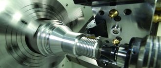
The screw-cutting lathe model 16K20 belongs to the category of universal equipment for processing metal parts. Its characteristics, of course, do not allow it to replace milling equipment, but make it possible to use it to perform a whole list of specialized operations. Such operations, in particular, include cutting threads of various types (metric, inch, modular, pitch), drilling, countersinking and other types of turning.
The capabilities of this screw-cutting lathe are such that it can be used to process workpieces from both hot-rolled and cold-rolled steel. Before the appearance of this machine, enterprises used the 1K62 equipment model, which is significantly inferior to it in all its characteristics. Thus, the advantages of the 16K20 screw-cutting lathe (compared to the previous model) include:
- operational safety;
- high reliability;
- the ability to process parts with high precision;
- simplicity and ease of maintenance;
- exceptional durability even with active use;
- high performance.
Read also: Knife steel characteristics table
Screw-cutting lathes 16K20 are used in enterprises that produce products individually or in small batches, as well as in tool shops, where such equipment can be used to perform both semi-finishing and finishing work.
Among the design features of this screw-cutting lathe, the following can be noted.
- The equipment frame is made in a box-shaped form and installed on a massive monolithic base, which gives high rigidity to the entire structure. Precision movement along the caliper frame and movable tailstock is ensured by reliable guides, which are heat-treated and ground.
- Depending on the type of processing and configuration, the workpieces can be fixed in the chuck or clamped in centers.
- The cutter holder device is designed to ensure reliable fixation of the tool.
- To install the spindle, high-precision (precision) rolling bearings are used, which are necessary for the accuracy of its location and rotation.
- The design of the 16K20 screw-cutting lathe provides a number of blocking and fencing technical elements that ensure safe work on it.
- To ensure processing accuracy, the machine is equipped with rulers with sights, which can be used to control the longitudinal as well as transverse movements of the tool.
- You can urgently turn off the support feed of a 16K20 machine using a special device installed on the apron of the machine.
The 16K20 tool holder on the machine support looks like this:
Machine tool holder 16K20
Due to the versatility, reliability, simplicity of design and maintenance of the 16K20 screw-cutting lathe, analogues of this equipment were produced at a number of domestic and foreign enterprises, where they were designated:
- MK6058 (6057, 6056) – Machine tool building in Moscow;
- 16V20P, 16V20 – Astrakhan Machine Tool Plant;
- ZHA-805 – Automatic machine tools plant in Zhitomir;
- 16B16 and modifications, Samat 400 – Srednevolzhsky Machine Tool Plant in Samara;
- GH-1840ZX (“Jet” – Switzerland), CU402 (“Vratsa” – Bulgaria), CD6140A (“Anhui Chizhou” – China), BJ1630G, CS6240, CS6240 (“Bochi” – China), CA6240B, CA6140A (“SMTCL” – China).
- KA-280 - in Kyiv.
- 16VT20P, 16VT20 - in Vitebsk.
Feed motion and thread cutting
The feed drive includes the following chains and components (see kinematic diagram):
- Thread pitch increasing link - provides an increase in the output rotation speed relative to the spindle speed in the ratio: 1:2, 1:8, 1:32. Provides a double block in the spindle head when connecting z = 45/45;
- Reverse mechanism - serves to change the direction of movement of the caliper with the same direction of spindle rotation. It is carried out by connecting the intermediate gear - snaffle;
- Guitar of replacement wheels - includes replacement gears K, L, M, N. Serves for relatively rare reconfiguration of speeds;
- Feed Box - The feed box receives movement from the headstock through the guitar and sets different rotation speeds for the lead shaft and lead screw;
- Feed mechanism - converts the rotation of the drive shaft into translational movement of the caliper, longitudinal, transverse or cutting slide. The lead screw must be turned off.
- The feed mechanism when cutting threads with a cutter converts the rotation of the lead screw into forward longitudinal movement of the caliper.
Kinematic diagram of the support and apron of the machine 16K20
Block diagram of feeds and thread cutting of a screw-cutting lathe 16k20
The feed movement is borrowed from the spindle in the spindle head when the z = 60/60 pair is running.
If it is necessary to increase the pitch, the movement is borrowed from shaft III with gear z = 45/45 engaged. In this case, the feed and thread pitch increase depending on the position of the blocks in 2; 8 and 32 times.
The reverse mechanism ensures right rotation of the lead screw through a pair of z = 30/45, left rotation through a gear z = 30/25 25/45.
When the machine leaves the factory, gears with a number of teeth z = 40/86, z = 86/64 in the replacement wheels K/L, M/N . This combination provides feeds and cutting of metric and inch threads in steps, the values of which are indicated in the table attached to the machine.
Kinematic chain of longitudinal and transverse feeds of the caliper
The kinematic feed chain coordinates the rotation of the spindle with the movement of the caliper in the longitudinal or transverse directions: for 1 revolution of the spindle, the caliper must move by an amount S.
Kinematic chain of longitudinal feeds of the caliper
The kinematic balance equation for the longitudinal feed chain has the form:
S = 1 rev. sp. · z1/z2 · π · m · z mm/rev ,
Where:
- z1/z2 — gear ratio of the feed drive from the spindle to the rack wheel;
- π·m·z is the length of the pitch circle of the rack and pinion wheel. π m z = 3.1416 3 10 = 94.248;
- m - rack module, m = 3 mm;
- z is the number of teeth of the rack and pinion wheel, z = 10.
The universal feed box 16B20P.070 provides longitudinal feeds (22 pcs), mm/rev:
- 0,05; 0,06; 0,075; 0,09; 0,1; 0,125; 0,15; 0,175; 0,2; 0,25; 0,3; 0,35; 0,4; 0,5; 0,6; 0,7; 0,8; 1; 1,6; 2; 2,4; 2,8; 2,4; 2,8
The equation of the kinematic chain to obtain the minimum longitudinal feed can be written in the following form:
Kinematic chain of transverse caliper feeds
The equation for the kinematic balance of the cross feed chain has the form:
S = 1 rev. sp. · z1/z2 · р mm/rev ,
Where:
- z1/z2 — gear ratio of the feed drive from the spindle to the rack wheel;
- p — pitch of the cross-feed screw, p = 5 mm
The complete kinematic balance equation for the minimum cross feed chain is:
Accordingly, the kinematic chain of the transverse feed coordinates the rotation of the spindle and the transverse lead screw; the amount of transverse feed with the same machine setup is 1/2 of the longitudinal feed.
The kinematic chain equation for obtaining the maximum lateral feed can be written as follows:
In the feed box of a 16k20 screw-cutting lathe, the feeds are not located in a geometric row, so the machine is set to the required feed according to the tables located on the headstock panel.
In the case of cutting precise threads, rotation can be transmitted from the replacement wheels directly to the lead screw with a pitch of t = 12 mm through shafts XII, XVII, XXIII with gear couplings M2 and M5 engaged, bypassing the feedbox mechanism.
and transverse feeds (24 pcs), mm/rev:
- 0,025; 0,03; 0,0375; 0,045; 0,05; 0,0625; 0,075; 0,0875; 0,1; 0,125; 0,15; 0,175; 0,2; 0,25; 0,3; 0,35; 0,4; 0,5; 0,6; 0,7; 0,8; 1; 1,2; 1,4
Kinematic chain for cutting metric threads
When cutting a thread, in one revolution of the spindle, the support (cutter) must move by the thread pitch Рр.
The kinematic balance equation for the metric thread cutting chain has the form:
S = Рм = 1 rev. sp. · z1/z2 · Рх mm/rev ,
Where:
- z1/z2 —gear ratio of the feed drive from the spindle to the lead screw;
- Px is the pitch of the machine lead screw in mm (Px = 12 mm).
Kinematic balance equation for cutting metric threads with a minimum pitch:
Kinematic chain for cutting inch threads
When cutting inch threads, the pitch is specified by the number of threads per inch, all thread parameters are expressed in inches (inch = 25.4 mm).
For inch pipe threads, the size in inches conventionally characterizes the clearance in the pipe, and the outer diameter is, in fact, significantly larger.
Inch thread pitch in millimeters:
Pd = 25.4/k mm/rev,
Where:
- k - number of threads per inch of thread (1″ = 25.4 mm);
Kinematic balance equation for cutting inch threads with a minimum pitch:
Kinematic chain when cutting modular threads
Modular threads are usually used when cutting worms.
The pitch of a modular thread is expressed through the module - a number that is a multiple of pi (3.14).
Modular thread pitch in millimeters:
Pm = 3.14 m mm,
Where:
- m is the thread pitch in modules;
Setting up a lathe for thread cutting
When cutting threads, the equations of kinematic chains are compiled based on the condition that during one revolution of the spindle the tool must move in the feed direction by the pitch Pp of the thread being cut.
Let us write the kinematic balance equation for cutting metric threads with a minimum pitch:
When cutting a modular thread with a minimum pitch, instead of replacement wheels z = 40-73, 73-64, wheels z = 60-73, 86-36 should be substituted into this equation. The kinematic balance equation for cutting inch threads in general form:
Setting up a modern universal screw-cutting lathe 1K620
for thread cutting comes down to setting up the drives of the main movement and the feed movement.
Setting the feed box to the pitch of the thread being cut is in most cases carried out using a table mounted on the machine, or according to a passport.
The feed box control handles are set to the position indicated in the table, and the reverse of the lead screw is set to the position corresponding to cutting a right-handed or left-handed thread, and, if necessary, turn on a link for increasing the thread pitch.
Rotation from the feed box is imparted to the lead screw, and the longitudinal movement of the caliper with the threaded cutter is activated when the split nut is closed.
When cutting high-precision threads or with a non-standard pitch, adjusting the longitudinal feed chain requires preliminary calculations, sometimes quite complex (for example, when adjusting a screw-cutting chain not with a feed box, but with a guitar of interchangeable wheels). Modern universal lathes provide the ability to completely disable the feed box; The driven shaft of the guitar is connected directly to the lead screw of the machine. In these cases, it is necessary to select replacement wheels from those included with the machine or make additional ones. The number of teeth on replacement wheels can be selected in two ways.
In the first method, the feed box levers are placed in a position in which the cut pitch is equal to the pitch of the machine lead screw. Thus, the gear ratio is equal to the pitch of the threaded screw divided by the pitch of the lead screw. In cases where the numerator or denominator of the gear ratio of a simple fraction will have factors that are inconvenient for converting them into the number of teeth of replacement gears, the calculation should be carried out using tables of gear ratios.
In the second method, the selection of replacement wheels is carried out according to one of the gear ratios of the replacement wheels available (even from other machines), or according to the gear ratio of the feed box.
If it is necessary to produce a thread with small pitch tolerances, and the machine lead screw has a manufacturing error, then the selection is performed using approximate methods.
Kinematic diagram of a screw-cutting lathe 16k20
Kinematic diagram of a screw-cutting lathe 16k20
Design of the spindle (front) headstock with gearbox
Gearbox of screw-cutting lathe 16k20
Spindle head of screw-cutting lathe 16k20
All gearbox shafts and the spindle rotate on rolling bearings, which are lubricated both by splashing (the gearbox is filled with oil) and by force, using a pump. The feed movement from the spindle is transmitted to the bit shaft and then to the feed mechanism.
Spindle revolutions per minute - forward rotation (22 pcs): 12.5-16-20-25-31.5-40-50-63-80-100-125-160-200-250-315-400-500 -630-800-1000-1250-1600.
Spindle revolutions per minute - reverse rotation (11 pcs): 19-30-48-75-120-190-300-476-753-1200-1900.
The spindle and all shafts are mounted on rolling bearings. The front spindle support contains a radial double-row roller bearing, in which preload is created by fitting the inner ring onto the tapered journal of the spindle. If you push the ring onto the cone with a nut, it expands and puts pressure on the rollers.
The rear spindle support has two angular contact ball bearings that absorb radial and axial loads; The preload is adjusted with a nut tightening the inner rings.
Shafts II…V of the gearbox are mounted on tapered roller bearings, which is convenient for assembly and disassembly; the preload is adjusted using pressure screws 3. Since shafts III and IV are long, a middle support is provided for them.
On the left side of the friction clutch 13, which reverses the movement of the spindle, there is a large number of disks, since large torques are required in the forward direction of rotation. A special feature of gear blocks is the adhesive connections between the rims and the hubs.
The wheel hub Z= 60 on shaft III is a band brake disc; The rod of the control mechanism, setting the clutch in the neutral position, turns on the brake (by pressing roller 1).
Feed box design of screw-cutting lathe 16K20
Machine feed box - unified unit 16B20P.070
and is a typical closed box design with movable units.
The connection between the spindle and the machine support to ensure optimal cutting mode is carried out using a feed mechanism consisting of a reversing device (bite) and a guitar, which change the direction and speed of movement of the support.
The feed box is mounted on the frame below the spindle (front) headstock and has several shafts on which movable gear blocks and switchable gear couplings are installed. In the right position of the clutch, the lead screw rotates, and in its left position (as shown in the figure), the drive shaft rotates through the overrunning clutch.
Feed box drawing for lathe 16k20
Feed box diagram for lathe 16k20
Adjusting the feed box of the machine 16K20
When repairing the machine, special attention should be paid to the correct installation of the gear shift mechanism mounted on plate 38, which is attached to the housing 3 of the feed box. In order to avoid disruption of the order of engagement of the gear wheels of the feed box during assembly, it is necessary to combine the marks marked on gears 51 and 52.
Node purpose
The tailstock of a metal lathe is a reliable support for securing the workpiece. In addition, it supports the second edge of the workpiece and ensures its stable rotation. During drilling, it is connected to the support with a grip. A drill of the required diameter is inserted into the quill chuck. In addition to drills, mounting is provided for: dies, taps, reamers, countersinks and other cutting tools. Such a wide range of tools used allows for a wide range of processing operations.
Gearbox (replacement gears, guitar)
The gearbox is used to transmit rotation from the output shaft (axis I) of the spindle head to the output shaft (axis II) of the feed box by installing combinations of replaceable gears in accordance with the diagrams in the table (Fig. 10). The machine can be set up to cut various threads.
Replacement gears K and N are mounted on splined shafts and secured with bolts 9 through washers 8.
Intermediate gears L and M are installed on the splined sleeve 10 of the axis 13, secured with a key in the required location of the groove of the bracket 3, which is fixed with a nut 6.
At the ends of the replacement gears K, L, M, N are marked (see packing list), the number of teeth z and the module m.
When fixing bracket 3 and axle 13, you need to install replacement gears with minimal radial clearance.
We must not forget about regular lubrication (see paragraph 6.2. “Lubrication chart”) of the replacement gears and bushing 10, which is lubricated through the oiler cap 12.
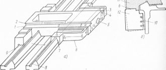
Bed, racks, lead screw, drive shaft and fast movement drive of the caliper
The tension of the drive belt for fast movements of the caliper is carried out by adjusting screw 3, which is locked with nut 2.
When cleaning the lead screw 13 and the drive shaft 14, it is necessary to remove the shields 9 and 10. To do this, you need to loosen the screws 19 and remove the shields from the side of the rear bracket 18.
Technical characteristics of the lathe 16K20
| Parameter name | 16K20 | 16K20P |
| Basic machine parameters | ||
| Accuracy class according to GOST 8-82 | N | P |
| The largest diameter of the workpiece installed above the bed, mm | 400 | 400 |
| Height of the center axis above the flat guides of the frame, mm | 215 | 215 |
| The largest diameter of the workpiece processed above the support, mm | 220 | 220 |
| Maximum length of the workpiece installed in the centers (RMC), mm | 710, 1000, 1400, 2000 | 710, 1000 |
| The greatest distance from the axis of the centers to the edge of the tool holder, mm | 225 | 225 |
| The largest diameter of the drill when drilling steel parts, mm | 25 | 25 |
| Maximum mass of workpiece processed in centers, kg | 460..1300 | 460..1300 |
| Maximum mass of workpiece processed in the chuck, kg | 200 | 200 |
| Spindle | ||
| Spindle hole diameter, mm | 52 | 52 |
| The largest diameter of the rod passing through the hole in the spindle, mm | 50 | 50 |
| Spindle rotation speed in forward direction, rpm | 12,5..1600 | 12,5..1600 |
| Spindle rotation speed in reverse direction, rpm | 19..1900 | 19..1900 |
| Number of forward spindle speeds | 22 | 22 |
| Number of spindle reverse speeds | 11 | 11 |
| Spindle end according to GOST 12593-72 | 6K | 6K |
| Tapered spindle bore according to GOST 2847-67 | Morse 6 | Morse 6 |
| Spindle flange diameter, mm | 170 | 170 |
| Maximum torque on the spindle, Nm | 1000 | 1000 |
| Caliper. Submissions | ||
| Maximum length of longitudinal movement, mm | 645, 935, 1335, 1935 | 645, 935 |
| Maximum length of transverse movement, mm | 300 | 300 |
| Speed of fast longitudinal movements, mm/min | 3800 | 3800 |
| Speed of fast transverse movements, mm/min | 1900 | 1900 |
| Maximum permissible speed of movement when working on stops, mm/min | 250 | 250 |
| Minimum permissible speed of movement of the carriage (support), mm/min | 10 | 10 |
| Price for dividing the longitudinal movement dial, mm | 1 | 1 |
| Transverse movement dial division price, mm | 0,05 | 0,05 |
| Longitudinal feed range, mm/rev | 0,05..2,8 | 0,05..2,8 |
| Transverse feed range, mm/rev | 0,025..1,4 | 0,025..1,4 |
| Number of longitudinal feeds | 42 | 42 |
| Number of cross feeds | 42 | 42 |
| Number of threads to be cut - metric | ||
| Number of threads to be cut - modular | ||
| Number of threads cut - inch | ||
| Number of threads to be cut - pitch | ||
| Limits of metric thread pitches, mm | 0,5..112 | 0,5..112 |
| Limits of pitches of inch threads, threads/inch | 56..0,5 | 56..0,5 |
| Limits of modular thread pitches, module | 0,5..112 | 0,5..112 |
| Limits of pitch thread pitches, diametric pitch | 56..0,5 | 56..0,5 |
| The greatest force allowed by the feed mechanism on the cutter is longitudinal, N | 5884 | 5884 |
| The greatest force allowed by the feed mechanism on the cutter is transverse, N | 3530 | 3530 |
| Cutting slide | ||
| Maximum movement of the cutting slide, mm | 150 | 150 |
| Movement of the cutting slide by one division of the dial, mm | 0,05 | 0,05 |
| Maximum angle of rotation of the cutting slide, degrees | ±90° | ±90° |
| Scale division of the tool slide rotation scale, deg | 1° | 1° |
| The largest cross-section of the cutter holder, mm | 25 × 25 | 25 × 25 |
| Height from the supporting surface of the cutter to the axis of the centers (cutter height), mm | 25 | 25 |
| Number of cutters in the cutting head | 4 | 4 |
| Tailstock | ||
| Tailstock quill diameter, mm | ||
| Cone of the hole in the tailstock quill according to GOST 2847-67 | Morse 5 | Morse 5 |
| Maximum movement of the quill, mm | 150 | 150 |
| Movement of the quill by one division of the dial, mm | 0,1 | 0,1 |
| The amount of lateral displacement of the headstock body, mm | ±15 | ±15 |
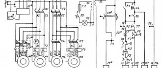
| Electrical equipment | ||
| Main drive electric motor, kW | 11 | 11 |
| Electric motor for fast movement drive, kW | 0,12 | 0,12 |
| Coolant pump electric motor, kW | 0,125 | 0,125 |
| Dimensions and weight of the machine | ||
| Machine dimensions (length width height) RMC=1000, mm | 2795 × 1190 × 1500 | 2795 × 1190 × 1500 |
| Machine weight, kg | 3010 | 3010 |
16K20 (1)
Ministry of Education and Science of the Russian Federation
FSBEI
HPE TSTU
Department: TM, MS and I
Laboratory work “Adjustment and adjustment of turning-screw-cutting
machine model 16K20"
Completed:
student of group STM-41
Checked:
Kolodin A.N.
Tambov 2013
Goal of the work:
study the design, principle of operation, kinematics and control of the screw-cutting lathe mod.16K20 and its main components, acquire practical skills in calculating machine settings for various types of work, and become familiar with its technological capabilities.
Tasks:
- Study the structure and operation of the machine and its components, kinematic diagram.
- Familiarize yourself with the procedure for setting up a machine to perform various turning operations (cutting threads of various types, machining conical surfaces, machining holes).
- Configure the machine to perform turning operations specified in the application table.
Guidelines
1. Purpose of the machine
and its individual components
The screw-cutting lathe mod. 16K20 is designed for processing external and internal surfaces of rotation, cutting threads of various types on them (metric, inch, modular, pitch, etc.) shaped and end surfaces, turning grooves, cutting and cutting Archimedean spirals at the ends.
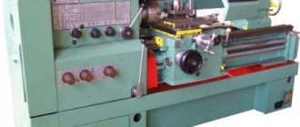
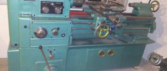
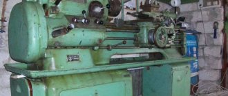
General view of the machine
2.Technical characteristics of the machine mod.16K20
The largest diameter of the part installed above the frame, mm - 400
Distance between centers, mm………………… 710,1000 and 1400
Spindle hole diameter, mm. . ……………………..………52
Number of spindle speed values ……………………24
Spindle rotation speed, rpm………………….12.5+1600
Feeds, mm/rev: longitudinal …………………… 0.05-2.8
transverse………………………………………………………………. 0.025-1.4
Thread pitch: metric, mm. . …………………….0.5-112
inch (number of threads per I")……….56-0.25
modular, module …………………………. 0.5-112
pitch, pitch…………………………56-0.25
Electric motor power, kW……………………… 10
3. Block diagram of turning group machines
Lathes of the turning group are designed for processing the external, internal and end surfaces of rotating bodies and cutting threads (screw-cutting lathes). Turning cutters are used as tools. Dimensional tools can also be used: drills, countersinks, reamers, taps, dies, etc.
The surfaces of bodies of rotation on lathes are obtained according to the scheme “trace” + “trace” or “trace” + “copying”. The first is the method of obtaining a guide, and the second is the generatrix of generating lines.
This implies the need to have in lathes a rotational movement of the workpiece B1 and a translational movement of the cutter P2 along the axis of rotation of the workpiece and P3 - perpendicular to its axis of rotation when turning the end surfaces. Moreover, to ensure the possibility of cutting threads with cutters, it is necessary that the movements of B1 and P2 be coordinated. Based on these considerations, the block diagram of a screw-cutting lathe can be presented as follows
Simple longitudinal turning is carried out by the implementation of two executive movements F (B1) and F (P2); end - F (B1) and F (P3). Thread cutting is carried out by one complex executive movement (two-element) F (B1 P2). The coordination of the elementary movements B1 and P2 is carried out by the internal kinematic connection B1→2→P2→ir→icp→3→4→t1→P2. The use of two parallel gears “screw-nut” and “gear-rack” is due to the following. When cutting threads, greater connection accuracy is required (B1 P2), for which a screw-nut transmission is used as it is more accurate. During normal turning, in order to avoid wear of the “screw-nut” pair, it includes a rack and pinion gear.
4. Main components of the machine and machine controls
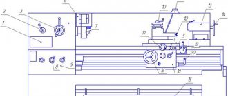
The machine consists of the following main components.
Main nodes:
1 — front cabinet; 2- belt drive; 3 — feed box; 4 — gearbox (guitar); 5 - spindle head; 6 — push-button station; 8 - bridge; 9 — lunette; 10 — caliper; 11 — tool holder; 12 - apron; 13 — protective screen; 14 - tailstock; 15 - bed; 16 - base; 17 — upper support (slide); 18 — lead screw; 19 — running shaft; 20 - spindle.
The bed serves as the basis for fastening the fixed components of the machine, to maintain the accuracy and rigidity of their relative position. The bed guides ensure the straightness of the longitudinal movement of the caliper carriage and tailstock. The headstock is used for
spindle mounts. The workpiece is supported and secured using various types of chucks, centers, mandrels or special fixtures. In the headstock there are gearbox mechanisms, which serve to change the spindle rotation speed, both in the forward and reverse direction of its rotation. A set of interchangeable gears is used to adjust the type and pitch of the thread. The feed box is used to change the feed amount, to adjust the type and pitch of the thread being cut. When cutting precise threads, the feed box is switched off. The support is used for fastening the cutter and for carrying out feeds: mechanical longitudinal or transverse and manual at an angle to the axis of the machine when processing short cones. The transformation of the rotational movement of the lead screw or lead roller into the translational movement of the support is carried out by the mechanisms of the machine apron. To turn cones with a short generatrix length, the tool holder guides are rotated by the angle of the cone. The tailstock is used to create a second support for the workpiece when processing parts, to fasten drills and impart axial feed to them, to shift the rear center from the axis of rotation for the purpose of turning flat cones.
Controls:
21, 35 — handles for engaging the friction clutch of the main movement drive; 22,23,24 — feed box adjustment handles; 25.7 — spindle speed adjustment handles; 26 — adjustment handle for thread pitch (normal or increased); 27 — handle for turning on the right or left thread; 28,29,31,33 — handwheels for manual movement of the caliper, cross slide, tailstock quill; 30 — handle for turning on automatic feed; 32.34 — quill and tailstock clamping levers.
5.Setting the main movement of the machine
The machine's gearbox consists of two kinematic chains.
Low spindle speeds are transmitted when enumeration is enabled along the circuit:
High spindle speeds are transmitted when the search is turned off through the circuit:
The search has the following gear ratios
Setting up the machine for processing conical surfaces
Method for processing conical surfaces.
- Wide incisors. Grinding is carried out with a cutter, the main cutting edge of which is set at an angle to the axis of the workpiece. The method is applicable for short cones (l≤15+20 mm). The processing scheme is shown in Fig.a.
- With the rotation of the upper slide (Fig.b). Conical surfaces with large apex angles are processed. When setting up, the upper slide of the caliper is installed at an angle α along the divisions on the flange of the rotating part of the caliper. The machine does not have a mechanical feed of the upper slide, so the feed is carried out manually by rotating the flywheel. In this case, it is difficult to obtain low roughness of the machined surface.
- Transverse displacement of the tailstock housing.
This method is used to grind long surfaces with a small cone angle. The displacement value h (Fig.c) of the tailstock is calculated using the following formulas: h=(Dd/2)∙(L/l) h=L tgα
Processing is carried out with longitudinal feed of the caliper. The accuracy of the method is relatively low.
Note
. Other methods of processing conical surfaces are also widely used, such as;
a) using a universal carbon ruler;
b) using special copying devices, for example, hydrocopying supports;
c) simultaneous activation of longitudinal and transverse feeds;
d) on computer-controlled machines.
However, the listed methods require special equipment for lathes (copy ruler, hydraulic support, etc.) or machines with wider technological or kinematic capabilities (methods “c” and “d”).
Scheme for processing conical surfaces