Restoring the carriage guides of a lathe support
TO
category:
Industrial equipment repair
Restoring the carriage guides of a lathe support
Next: Repair of milling machine consoles
For caliper carriage guides, wear occurs on surfaces 1, 2, 3, 4,7, and surfaces 1, 2, and wears more in the middle part. They become concave and, as a result, the mutual parallelism of these surfaces and the parallelism of the axis of the screw hole are disrupted. Increased wear of surfaces entails tilting of the carriage towards the apron, as shown by the dotted lines on the top of Fig. 1, b.
In addition, due to the uneven distribution of cutting forces on the surfaces, the carriage gradually rotates. This in turn causes uneven wear of the guides along the length. The perpendicularity of the transverse guides and relative to the longitudinal guides is disrupted.
The lower surface, where the apron is attached, loses parallelism with the longitudinal guides and warps in the transverse direction, as a result of which the apron becomes tilted towards the bed, in the direction of decreasing the angle formed by the surfaces of the carriage and the bed for attaching the feed box.
During repairs, it is necessary to restore the original (within 0.03 mm for a length of 300 mm) accuracy of many coordinates, including: parallelism of surfaces 1, 2, 3 of the screw axes in the horizontal and vertical planes, parallelism of surfaces, planes for attaching the apron, perpendicularity of transverse guides , (along its line) guides; perpendicularity to the surface of the plane for attaching the feed box to the frame (not shown in the figure); parallelism of guides 7, 8 to the surface.
Rice. 1. Wear of the guides of the lathe support carriage: a - location of the guides, b - tilt of the carriage and apron due to wear of the guides
It is rational to start repairing guide carriages from surfaces 1, 2, 3, 4, and to align them to the axis of the hole, install a control mandrel into it. However, the geometric accuracy of these holes is often compromised. Therefore, it is advisable to use as a base a face that is always perpendicular to the axis of the hole for the cross-feed screw and a plane.
The carriage guides can be repaired in the following ways: - all guides are planed and scraped or limited to scraping or grinding alone; - surfaces, and are restored by planing and compensate for wear with fittings made of cast iron, brass, textolite, nylon, plastic compositions, etc.
Below we consider a rational way to restore carriage guides using high-speed milling of both surfaces and plastic compositions.
For repairs, they use a device that is a two-stage base with T-shaped slots and movable jacks.
The device is placed on the table of a vertical milling machine, and the carriage is attached with its surface to the upper stage of the device with screws through the existing holes for attaching the apron using movable nuts located in T-shaped slots.
Rice. 2. Installation of the carriage on the fixture
Then movable jacks are placed under the longitudinal guides of the carriage and adjusted with screws and nuts so as to provide the necessary support, eliminating deformation of the carriage when securing it with a clamping device. Next, using an indicator (not shown in the figure), the surface of the carriage is aligned (by turning the device on the machine table) so that it is parallel to the movement of the table in the transverse direction, allowing deviations of up to 0.03 mm along the entire length, while the axis of the hole will be perpendicular to the direction lateral movement of the table. After this, the device is secured to the machine table using clamps (not shown in the figure). After fastening, they begin to process the transverse guides of the dovetail shape using high-speed milling.
Milling is carried out with an end mill sharpened in accordance with the angle of the guides, equipped with cutting plates made of carbide. The cutting speed should be 3-4 m/s at a feed of 200 mm/min. First, the surfaces are processed simultaneously in one or two passes before wear is removed, then, without changing the position of the cutter, the surfaces are processed in one pass.
The result is high precision execution to the limit! 0.01-0.03 mm and surface quality according to 7-8th roughness classes. The accuracy of the carriage coordinates is restored automatically; the transverse guide surfaces 1,2,3,6 are mutually parallel to the cross-feed screw and the plane for attaching the apron, including in size.
The surfaces are restored after the restoration of the transverse guides. Restoration is carried out with plastic compositions or metal linings made of plastic and metal jb.
Rice. 3. Sealing the carriage guides for filling with acrylic plastic
Restoration of guides with plastic compositions is carried out in the following sequence.
1. Repair the transverse guide carriages using the methods indicated above. 2. A layer 2-3 mm thick is removed from the surfaces of the carriage mating with the frame guides. The surface roughness must correspond to class 1. 3. Four holes are drilled on the carriage, threads are cut and screws with nuts are installed, the same two screws are installed on the rear wall of the carriage (not shown in the figure). In the middle part of the guides, a hole with a diameter of 6-8 mm is drilled. 4. Apply a thin, uniform insulating layer to the repaired frame guides using a bar of laundry soap. 5. Pre-planed guide carriages are degreased with a light cloth swab soaked in acetone and dried for 15-20 minutes. 6. The carriage is installed on the repaired frame guides, the rear clamping bar is attached, the apron, feed box, lead screw, shafts and support bracket (not shown) are installed, located at the right end of the frame. The parallelism of the screw axes and shafts to the frame guides is preliminarily verified. 7. Install a device for checking the perpendicularity of the carriage guides and a device for checking that the axes of the screws and shafts are parallel to the guides. This device is attached to a universal bridge. 8. Set the levels, placing them as shown in the figure. 9. Adjust the position of the carriage using four screws. In this case, according to the indicator readings, the perpendicularity of the transverse guides of the carriage to the guides of the bed is established. The level determines the perpendicularity of the surface of the carriage for attaching the apron and the plane of the feed box on the frame. Using a level, the parallelism of the carriage plane under the apron to the bed guides is established. The device is used to check the alignment of the holes for the lead screw and the self-propelled shaft in the feed box and apron. 10. After all positions have been adjusted and the adjusting screws have been tightened with locknuts, remove the lead screw, self-propelled shaft and apron. Then the surfaces of the carriage and bed are sealed with plasticine from the side of the apron and the rear clamping bar. Funnels and 5 are made from plasticine along the edges of the carriage, and funnels are made around the drilled holes in the middle part of the guides. 11. Prepare an acrylic plastic solution and pour it into the middle funnel of one of the guides until the level of liquid plastic in the outer funnels is equal to the level in the middle funnel. The second guide is also poured. 12. Maintain the carriage on the frame for 2-3 hours at a temperature of 18-20 °C. 13. Remove the carriage from the frame guides, clean it of plasticine, remove the tides of plastic, make grooves for lubrication, and seal the holes of the set screws with stoppers or acrylic plastic.
Rice. 4. Adjusting the position of the carriage with screws: 1 - device for checking the deviation from perpendicularity of the carriage guides. — indicator. 3, 4 — levels. 5, 6 - set screws, 7 - universal bridge, 8 - device for checking deviations from parallelism of the screw axes, 9 - apron, 10 - carriage, 11 - shaft, 12 - lead screw, 13 - feed box
Rice. 5. Checking the console guides on the assembled milling machine: a - checking the deviations of the guides from being parallel to the axis, b - checking the deviations from the perpendicularity of the table surface by the console guides
Varieties
To bore the jaws of a lathe chuck, it is necessary to choose the optimal method for a particular type. Several types of cams are produced, each of which has design features.
Direct
This type of cam is designed to clamp a workpiece with a shaft on the outside and for a workpiece with a hole on the inside. The cams are directly located on top and grip the part.
Reverse
Necessary for clamping the workpiece from the outside. Used for processing hollow blanks so that there is something to cling to.
Invoices
This is a composite version of the cartridge, which is made of non-ferrous metal or stainless steel. Used when working with large-scale projects
This variation is used when working with workpieces of large diameter, and it does not matter whether they are long or short
Prefabricated
A metal cam in this type is mounted on a steel rail. Alloy steel is used, and the cam teeth are ground, hardened and carburized.
Repairing the caliper carriage
Restoring the accuracy of the lower guides, which are associated with the base guides, without taking into account wear - this is where you need to start repairing the caliper carriage.
Also, when repairing the carriage, it is necessary to restore the perpendicularity of its plane under the apron of the base plane (under the gearbox).
The location of these planes is measured by a level. The thickness of the probe placed under the carriage will determine the level of deviation (value).
The parallelism of the longitudinal guides and their parallelism to the axis of the transverse feed are also subject to restoration.
It should be noted that repairing a caliper carriage is a very labor-intensive process; it is very difficult to do it yourself, so the company must schedule maintenance of the device on a schedule.
The carriage guides can be restored using compensation pads or acrylic plastic.
The cross slide of a screw-cutting lathe can be repaired by grinding. The rotary sled begins by scraping the surfaces, after which they begin sanding.
If necessary, the upper skids are also repaired.
To do this, the surface is scraped, aligned, polished, after which the accuracy of the surfaces’ mating with the guides of the rotary slide must be checked.
See the video for scraping the cross carriage.
Video:
Wedge restoration
If the wedges are worn out a lot, repair usually comes down to their complete replacement, which is associated with additional costs of metal and time spent on making new wedges.
Repair experience using new technology shows that all wedges, regardless of their wear, can be restored. The new repair technology is based on the use of styracrylic and appropriate preparation of wedges for pouring.
Experience shows that the labor intensity of repairing wedges using the proposed technology is reduced by approximately 35%, while manual scraping work associated with adjusting the wedges in place is almost completely eliminated.
The technological process for restoring wedges with styracrylic (Fig. 72) is presented in table. 12.
Schedule and composition of repair and maintenance work
When the machine operates under normal operating conditions and compliance with all operating and maintenance rules specified in this manual, the overhaul cycle (service life before major repairs during two-shift operation) is (mainly) at least 9 years when processing steel (mainly), and at least 8 years for cast iron years.
Maintenance and repair work is recommended to be carried out according to the repair work schedule (Fig. 39).
Machine inspection
- External inspection of the machine (without disassembling to identify defects) of the condition and operation of the machine as a whole and by components;
- Inspection and check of the condition of the main movement and feed drive mechanisms;
- Adjusting the table lead screw clearances;
- Spindle bearing adjustment;
- Checking the operation of speed and feed switching mechanisms;
- Regulation of the mechanisms for switching on cam clutches and feeds and the high-speed friction clutch;
- Adjustment of table wedges, slides, console and trunk;
- Inspection of guides, cleaning of nicks and burrs;
- Tightening loose fasteners;
- Checking the operation of the limiting cams;
- Checking the condition and minor repairs of cooling and lubrication systems;
- Checking the condition and repairing protective devices;
- Identification of parts that require replacement during the next repair (starting with the second minor repair);
Small machine repair
- Partial disassembly of components;
- Flushing all components;
- Adjustment or replacement of rolling bearings;
- Cleaning burrs and nicks on gear teeth, crackers and shift forks;
- Replacement and addition of friction discs of the high-speed clutch (starting from the second repair);
- Scraping and cleaning of wedges and strips;
- Cleaning the lead screws and replacing worn nuts;
- Cleaning nicks and burrs on the guides and working surface of the table;
- Replacing worn and broken fasteners
- Checking and adjusting the mechanisms for switching on speeds and feeds;
- Repair of lubrication and cooling systems;
- Testing the machine at idle speed, checking for noise, heating and accuracy of the workpiece.
Specifications
- Accuracy group – N.
- Center height (mm) – 215.
- Ø standard cartridge – 200 or 250 mm.
- The speed range of rotation of the spindle shaft in the direct direction (rpm) is 12.5–1.6*103. Adjustment discrete number of gears 24.
Moreover, both in the forward and reverse directions there are 2 gears with a frequency of 500 and 630 rpm. Therefore, some sources talk about 22 forward and 11 reverse transmissions.
- The speed range of rotation of the spindle shaft in the reverse direction (rpm) is 19–1.9*103. Adjustment discrete number of gears 12.
- Feed range (mm/rev): along the axis – 0.05–2.8; across 0.025–1.4.
- The pitch range of metric threads is 0.5–112 mm.
- The range of modular thread pitches is 0.5–112 modules.
- The range of inch thread pitches is 56–0.5 threads/inch.
- The range of pitch thread pitches is 56–0.5 pitches.
Limit parameters
- The maximum permissible diameter of a “disc” workpiece turned over the bed is 400 mm.
- The maximum diameter of the “shaft” type workpiece turned over the caliper is 220 mm.
- Limit length of the workpiece to be turned (mm) – 710, 1000, 1400, 2000.
- Limit length of turning (mm) – 645.935, 1335, 1935.
- The Ø of the “rod” type workpiece is no more than 50 mm.
- The weight of the workpiece fixed for processing in centers (no more) is 460, 650, 900, 1300 kg.
- The weight of the blank fixed for processing in the chuck (no more) is 200 kg.
- The force developed by the feed unit at the stop (no more) is 800 kgf along the axis, 460 kgf across it.
- The force developed by the feed unit on the cutter (no more) is 600 kgf along the axis, 360 kgf across it.
Some features of scraping guides
Since scraping is one of the most common methods for repairing bed guides, we will consider the sequence of performing this technological operation.
- The areas under the tailstock that suffer the least wear are treated first.
- Then the lathe components in question are processed under the clamping bars and under the carriage. Deviations from parallelism after such processing should not exceed 15 µm along the length of the elements.
- After this, the guides of the transverse caliper are scraped, checking their straightness and parallelism.
- The next stage of repair is processing the counter guides of the carriage. Monitoring the implementation of this process, in which parallelism between the screw axis and the guides must be ensured (divergence - no more than 35 microns), is carried out using a triangular ruler.
- If the longitudinal guides of the carriage are worn out sufficiently, anti-friction compounds must be used to repair them. After performing this procedure, the following parameters are monitored: the alignment of the running shaft and its landing zone; reliability of engagement of the rack and pinion gear and the rack itself, ensuring accurate movement of the carriage in the longitudinal direction; perpendicularity to the axis of the spindle assembly and the transverse movement of the support.
- After this, the tailstock of the lathe (or rather, the guides along which this unit moves) is repaired, for which an antifriction compound is also used.
Tailstock
The tailstock is movable and is used to secure the part to the spindle. It consists of 2 parts: the lower one - the main plate and the upper one, which holds the spindle.
Sectional view of the tailstock
The movable upper part moves along the lower perpendicular to the horizontal axis of the machine. This is necessary when turning cone-shaped parts. A shaft passes through the headstock wall; it can be rotated by a lever on the rear panel of the machine. The headstock is fastened to the frame using ordinary bolts.
Each lathe is individual in its layout, the device and circuit may differ slightly in detail, but in small and medium-sized machines this option is most common. The layout and layout of heavy large lathes differs depending on their purpose; they are highly specialized.
Character of wear and technical requirements for repair of guide frames
Surfaces 3, 4 and 6 (Fig. 87, a) - the guides along which the tailstock of the lathe moves, wear out significantly less than surfaces 7 and 8 of the front caliper guide. Surfaces 1, 2, 10 wear out somewhat less. Surfaces 5, 9, 11 and 12 practically do not wear out. The different amounts of wear on the guide surfaces are explained by the fact that when the assembly units, tailstock and caliper move, these surfaces are subject to different loads.
Based on GOST 18097-72, when repairing lathe beds, the following requirements should be met:
- the guides must be straight, the permissible convexity is 0.02 mm per 1000 mm of length;
- surfaces 2, 3, 4, b, 7 and 8 must be parallel in the horizontal plane, not have a spiral curvature observed when the guides are twisted, as if along a helical line, permissible deviation is 0.02 mm per 1000 mm of length;
- surfaces 7 and 5 must be parallel to surfaces 11 and 12 under the rail, permissible deviation is 0.10 mm over the entire length of the frame;
- surfaces 3 and 4 must be parallel to surfaces 7 and 8, permissible deviation is 0.03 mm over the entire length of the frame;
- surfaces 1 and 10 must be parallel to surfaces 2,7 and 8, the permissible deviation is 0.03 mm over the entire length of the frame.
The durability of the bed guides mainly depends on the operating mode of the machine and the quality of maintenance.
Table of contents
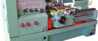
Lathes are widely used in modern industry, for example, models such as the TV-320 screw-cutting lathe, as they allow you to perform many operations on processing cylindrical parts. Their design largely depends on the models, but there are always similar elements, since the main parts are the same for all, even if they have their own characteristics. The lathe support is one of the most important parts of the machine as it is responsible for mounting the cutter. It was its appearance that made a revolutionary step in machine tool building. This element is intended to move the cutting tool, which is located in the tool holder, when processing the workpiece in several planes.
photo: lathe support
Movement is carried out in three main directions relative to the machine axis:
Movements in given directions are carried out both manually and mechanically.
Lathe support device
photo: lathe support device
The lathe support has the following components:
- Lower slide (or longitudinal support);
- Lead screw;
- Cross slide (or cross slide);
- Rotary plate;
- Guides;
- Cutting head (tool holder);
- Screw;
- Fastening bolts;
- Fastening handle;
- Locking nut;
- Upper slide;
- Guides;
- Handle for moving the rotary plate;
- Handle for turning on automatic feeds;
- A handle that provides control of movement along the bed;
The principle of operation of the caliper
The support of a lathe has a very complex control system, since it includes many parts. Each of the elements performs its own function, ensuring the overall performance of the mechanism. For example, the support of a screw-cutting lathe has a lower slide No. 1, which can move along the bed guides during operation to get to the workpiece. Movement is regulated by handle No. 15. Thanks to movement on the slide, longitudinal movement along the workpiece is ensured.
The transverse support of the T3 lathe also moves on the same slide, which carries out transverse movements along its guides No. 12. Thus, all this covers the movement area, which lies perpendicular to the axis of rotation of the workpiece. By the way, if you are interested in the architectural design of buildings and structures, go to the website https://aec-project.ru/services/proektirovanie/.
On the cross slide there is a rotating plate No. 4, which is attached to it with a special nut No. 10. Guides No. 5 are installed on the rotating plate, along which the upper slide No. 11 runs. The upper slide is controlled using the rotary handle No. 13. The upper slide rotates in a horizontal plane simultaneously with the plate. It is this unit that ensures the movement of the cutter, which is carried out at an angle to the axis of rotation of the part.
The cutting head, or as it is also called - the tool holder, No. 6 is fixed on the upper slide using special bolts No. 8 and handle No. 9. The movement from the caliper drive is transmitted through lead screw No. 2 to the drive shaft, which is located under this same screw. This can be done either automatically or manually, depending on the model.
Basic caliper movements
- Transverse movement is carried out perpendicular to the axis of rotation of the workpiece and is used in cases where it is necessary to machine something deep into the surface of the workpiece;
- Longitudinal movement is carried out along the workpiece and is used in cases where it is necessary to remove the top layer or grind a thread on the workpiece;
- Inclined movement is carried out along an inclined plane and significantly expands the processing capabilities of this equipment.
Adjusting the lathe slide
The support of a lathe wears out during its operation and requires adjustment of individual parts to continue working correctly:
- Adjusting the gaps. As the slide guides wear, a gap appears that should not exist. Its appearance can cause interference in the uniform movement of the sled, jamming in one place and lack of swaying when lateral forces are applied. To correct this situation, it is necessary to move the guides to the proper position and eliminate the excess gap. This is done using wedges, and the carriage is pressed against the guides.
- Backlash adjustment. If play appears in the screw drive, it can be easily eliminated by adjusting the fastening nut located on the device.
- Adjusting the seals. During prolonged work at the ends of the carriage protrusion, the seals become clogged and worn out, which can be easily seen by the appearance of dirty streaks that remain when the frame moves. In this case, to adjust the device, you should wash the felt padding and then soak it in oil. If it is completely worn out, it is easier to replace it with a new one.
Lathe support repair
The support of the 1K62 lathe wears out over time and may break. Most wear is noticeable along the guides of the device. Over time, the surface of the guide slide can form small depressions that interfere with normal movement. To prevent this, it is necessary to ensure timely care and lubrication, but if this does happen, then the surface of the guides must be leveled or replaced if repair cannot be achieved.
Repair cost
The purpose of the overhaul is to restore the initial accuracy and safety of service of a machine with an expended resource. The cost of overhauling a lathe is usually less than 50% of its market value: for this reason, repairing it is cheaper than purchasing a new one. In addition, repairs are often ordered for original machines that are no longer in production or are made according to a special order.
Major repairs include:
inspection of equipment performance before disassembly;
- disassembly, washing, cleaning, troubleshooting of worn parts;
- grinding and restoration of the base surface;
- replacement of parts when repairing units if they cannot be restored;
- if necessary, replace or improve the electrical control system;
- galvanizing or painting parts, if they need to be processed in this way;
- assembly of a repaired machine;
- checking equipment for accuracy in accordance with specifications;
- checking operation at idle and under load;
- ultimately – commissioning.
In addition, the price for repairs depends on the type and type of turning equipment and the degree of wear of parts.
It is worth understanding that lathes are expensive equipment. Therefore, before you start repairing yourself, you need to weigh the pros and cons. If you lack experience, you can render it completely unusable.
Areas of use of turning equipment
Screw-cutting lathes vary in weight and size, which directly depends on the industry where they are used. They can produce short and long, thin and wide parts. These lathes can cut internal and external threads on parts. The heavier the part, the more massive the machine for processing it.
Light weight turning equipment is used:
- in experimental workshops;
- in instrument making;
- in the manufacture of watch movement parts.
This type may have a mechanical supply of blanks to the cutter, which allows for faster production of identical parts, if necessary, to produce them in small batches. For the production of piece products, this mechanism is not required, which will be reflected in the design of the lathe.
In the industrial production of threaded parts and tools, medium-weight machines are more often used. Their design contains many automatic systems, which, along with rotary mechanical parts, require preventive checks and debugging. Moving, twisting, rotating, cutting and drilling parts require regular lubrication.
Heavy weight turning equipment is used for more repetitive operations. On it are machined:
- shafts;
- turbines;
- wheels for trains.
Despite the small range of products and a small selection of operations, these machines cannot be called simple. There are also many components in its design that require constant care and monitoring. Lubrication and cleaning of parts becomes more difficult due to their heavy weight.
Guide repair methods
The choice of method for repairing the guides of lathes (it is quite difficult to carry out such repairs yourself, without special equipment) depends on how badly these structural elements are worn, what hardness they have, how well technically equipped the repair team that will carry out this work is. difficult procedure.
Worn lathe bed guides
Bed guides that have undergone significant wear after long-term use can be restored in different ways: planing, milling, scraping (with or without lapping), pulling, grinding, rolling using special rollers. The most common methods used to overhaul a lathe bed include planing, scraping, and sanding.
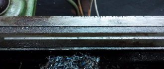
The amount of wear on the guides can be determined only after all dirt and existing nicks have been removed from their surface. To determine the gaps present on these components of the lathe, apply a metal ruler to them and, using a feeler gauge, identify the most worn areas that require urgent repairs, taking measurements every 30–50 cm.
Checking the bed using a homemade device
Experienced specialists can identify the most worn areas of the bed guides using thin paper, the thickness of which does not exceed 0.02 mm. Such paper is placed on the lathe components in question and pressed against them with a metal ruler. In those places where the guides have not undergone serious wear, the paper does not pull out from under the ruler, but breaks off along its edge.
Determination of the least worn areas of the bed
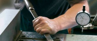
To perform scraping, which is carried out as part of a major overhaul, the equipment frame is installed on a rigid base, checking the position of its elements in the longitudinal and transverse directions and, if necessary, using shoes and wedges to adjust its location.
When checking the condition of the bed guides and the degree of their wear, those parts that are located under the tailstock are used as reference surfaces (they are the ones that are subject to the least wear during operation). After each scraping stage, these lathe components are checked for parallelism and curvature.
Grinding bed guides in garage conditions
Grinding the bed guides, compared to the scraping operation, is characterized by higher productivity, but it is not advisable to use this method when restoring unhardened components.
In order for the lathe bed to be polished efficiently, all nicks and burrs must be thoroughly cleaned. Then the frame for repair is fixed on the work table of the longitudinal planing machine, ensuring the parallelism of its surfaces and the direction of its movement. In addition, using a level that is installed on the tailstock bridge, check the curvature of the guides. Only after this they begin to grind these nodes.
As before grinding, before finishing planing, the frame should first be cleaned of existing nicks and secured to the working surface of the longitudinal planing machine, checking that its elements are parallel to the direction of its movement.
When using this repair method, the bed guides are processed with a cutter in 3–4 passes, after which their parallelism, straightness and twisting are checked. If, after processing, all the geometric parameters of the units being repaired meet the requirements, the frame is detached from the surface of the working table of the longitudinal planing equipment.
Videos of such restoration operations show that it is almost impossible to do them yourself without special equipment for repairs.
Machining the outer cones with the upper caliper slide rotated
The essence of the method for processing outer cones with the upper slide of the caliper rotated. With this method of processing cones, the rotary slide of the caliper is installed as shown in Fig. 154. In this figure: 1 - the workpiece (its front part is a cone); 2 — upper caliper slide; 3 — handle of the feed screw of this slide; 4 - cutter. By rotating handle 3, we will feed cutter 4, and it will process the conical part of part 1.
Determining the rotation angle of the upper caliper slide. The angle of rotation of the upper slide of the caliper when processing a cone is determined by the following rule.
In order for the inclination angle of the cone being processed to be equal to the required one, it is necessary to install the upper slide of the support at an angle to the center line of the machine equal to the inclination angle of this cone.
Rice. 154. Machining the cone with the upper caliper slide rotated
Counting the rotation angle of the upper caliper slide. The angle of rotation of the upper slide of the caliper is measured according to the divisions marked (Fig. 154) on the supporting flange 5 of its rotating part. Each such division usually corresponds to 1°, so smaller readings (1/2°, 1/4°) have to be done by eye.
Disadvantages of the method of processing the outer cones with the upper caliper slide rotated. The main disadvantage of this method is that processing is usually carried out with manual feed of the cutter, because Only large lathes have automatic feeding of the upper slide of the support. Manual feed is often uneven, resulting in unsatisfactory cleanliness of the machined cone surface. The length of the cone processed by the method under consideration is limited by the largest movement of the upper slide of the support, which even on such a modern machine as 1K62 is only 140 mm. It should be noted, finally, that processing even such relatively short cones with manual feed is tiring for the turner.
Outer cones machined with the upper caliper slide rotated. From the above it follows that the conical surfaces of the part can be processed with the upper slide rotated:
- if the length of the cone generatrix is small;
- if the cone being processed has a large slope angle;
- if high accuracy of the slope angle is not required;
- with low requirements for surface cleanliness.
Checking cones processed with the top slide rotated. The measurement of such cones, mostly short ones, is carried out with goniometers, for example a universal one (Fig. 155, a, b).
Rice. 155. Universal protractor (a, b) and examples of its application (c, d, e)
The main part of the universal protractor is disk 6, which is integral with ruler 9. A scale with degree divisions is applied around the circumference of the disk. The rotary disk 2 can be installed in the required position relative to the disk 6 and secured by means of the head 5. Attached to the rotary disk is a vernier 1, each division of which corresponds to 5 minutes, and a holder 8 of the ruler 4. The ruler can be secured in the required position by the head 7.
Rulers 9 and 4 can be installed in such a position that the angle formed by their working edges will be equal to the required one. The value of this angle is measured using the scale of disk 6 and vernier 1, as in the case of determining the readings of a caliper. Let us assume that after fixing the rotary disk 2, the vernier 1 has taken the position shown in Fig. 1 relative to the scale of disk 6. 155, b. The zero line of the vernier has already passed the 12th line of the scale of disk 6, and the 40th line of the vernier most closely matches one of the scale lines. In Fig. 155, b these strokes are marked with an asterisk. This means that the angle between the working edges of rulers 4 and 9 at their given position is 12° 40′.
Additional ruler 3 is used when measuring acute angles; in this case, whole degrees are counted not from zero, but from the 90th stroke of the scale of disk 6.
In Fig. 155, c shows checking the angle at the apex of the working cone of the center of the lathe with a universal goniometer, and in Fig. 155, d, e - checking the angles of the bevel gear.
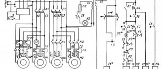
Electrical circuit diagram
There are 3 operating voltages in electrical equipment:
- Motor power supply –380V.
- Automatic - 110V.
- Workplace lighting – 24V.
List of machine electrical components:
- R – Load indicator E38022 (ammeter ~20A).
- F1 – Current protection circuit breaker AE-20-43-12.
- F2 – Automatic AE-20-33-10.
- F3, F4 – E2782—6/380 – fuse link.
- F5 – TRN-40 – electrothermal protection.
- F6, F7 – TRN-10 – electrothermal protection.
- N1 – safety light-signal device UPS-3.
- N2 – NKSO1X100/P00-09 – electric lamp with S24-25 lamp.
- N3 – KM24-90 – switching lamp.
- K1 – PAE-312 – remote magnetic starter.
- K2 – PME-012 – remote starter.
- KZ – RVP72-3121-00U4 – time delay relay (Limit of operation of the main motion electric motor without load).
- K4 – RPK-1-111 – engine starter.
- M1 – Main motion electric motor 4A132 M4, rated power 11 kW.
- M2 – 4А71В4 – electric motor (accelerated displacement of the caliper).
- M3 – Electric pump PA-22 (emulsion supply).
- M4 – 4A80A4UZ – asynchronous electric motor.
- S1 – VPK-4240 – limit switch (Distribution device door).
- S2 – PE-041 – rotary control switch (unlocking S1).
- S3 and S4 – PKE-622-2 – push-button control unit.
- S5 – MP-1203 – microswitch.
- S6 – VPK-2111 – push-type limit switch.
- S7 – PE-011 – rotary control switch.
- S8 – VPK-2010 push-type limit switch.
- T – TBSZ-0.16 – step-down transformer.
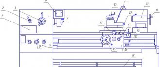
Diagram of lathe controls
Lathe repair cost
| Type of work | Price |
| Spindle Prevention | 9,000 rub. |
| Troubleshooting clamping devices | 19,000 rub. |
| Burnout (damage) of the stator winding | 30,000 rub. |
| Replacing bearings with rotor balancing | 50,000 rub. |
| Replacing spindle sensors | 10,000 rub. |
| Maintenance | 10,000 rub. |
| Non-standard work | 10,000 rub. |
| Major renovation | 50,000 rub. |
| Modernization of machine tools | 30,000 rub. |
Our main specialization is machine repair
If your machine does not work, our specialist will arrive as soon as possible and fix it. Call and consult by phone: 8
Technologies
Thanks to the use of modern devices, we can more accurately identify faults. And we save your money on repairs
Ideas
If your machine does not break down as usual. We will send it to our technicians and they will solve any problem
Speed.
You need the machine to work as quickly as possible. Our desires coincide.
Read useful information:
Repair of turret lathe
Any equipment fails sooner or later, this also applies to a commodity turret machine. In order for the machine to serve for a long time, and for the products made on it to meet the standards, it is necessary to carry out repairs and maintenance regularly.
Further
Machine head repair
The headstock is an important element of the machine. If this part fails, it is very difficult to cope with the repair yourself and you have to contact specialized workshops
How to prevent breakdowns, what is important to know when doing your own repairs and how much the services of qualified craftsmen cost - all this can be found in the article
Further
Repair of the electrical part of the machine
The slightest malfunction of the electrical part of the machine can disrupt the plant’s work schedule
It is important to be able to identify the source of the problem and eliminate it
Further
Turret machine repair
In case of significant breakdowns of the turret machine, a lot of difficulties can arise. In the article you can learn about the types of such equipment, as well as how to carry out repairs yourself and how much the help of specialists will cost.
Further
Daily care
The most reliable care for a lathe is to prevent damage to it. Preparation for the next work shift should be carried out immediately after finishing work and disconnecting the machine from the power supply. At this stage of maintenance, the following operations are performed:
- Chips and other technical debris are swept away from the surface.
- It is necessary to dissolve oil and dirt with kerosene and wipe dry with a rag.
- To avoid corrosion, all parts that do not have a paint coating are lubricated with oil.
- The oil cans are filled with grease.
Before starting a shift, it is necessary to check the presence of lubricant and inspect the equipment for damage or loose parts. During work, it is necessary to observe safety precautions when working with turning mechanisms - this will minimize injuries in the workplace and reduce the risk of equipment breakdown. During work you must:
- The use of protective screens, which will avoid clogging the lathe with metal shavings and small abrasive particles that arise during processing of the part.
- Timely replacement of drilling and cutting parts.
- Control over the reliability of fastenings of cutters and drills.
- During operation, do not allow the formation of long chips, which, if wound around the rotating parts, can damage the mechanism.
- You can turn on the machine only after the cutter is lowered onto the blank, in the place specified in the drawing.
Video covering basic maintenance principles.
Types and features of repair work
The classification of all repair work carried out is carried out on the basis of a system of planned preventive maintenance (PPR). This complex includes:
- technical (overhaul) maintenance – ensures the operation of the machine between repairs. Maintenance involves caring for the equipment in use and minor repairs. Can be performed by machine operators and mechanics on duty;
- current repairs are carried out during the operation of the equipment to ensure its guaranteed performance. During the repair process, parts of the machine are replaced or restored, as well as the necessary adjustments and adjustments;
- major repairs - carried out to restore the serviceability of equipment. When performing a major overhaul, it is possible to replace the main components of the machine;
- Unforeseen breakdowns and emergencies are eliminated during unscheduled repairs. In this case, only damaged elements are replaced or restored.
Preparatory work
Before starting repair work, it is necessary to identify and determine all faults. To do this, the machine must be carefully inspected, checked for accuracy, read the entries in the fault logs, and assess the scope of repairs. It is necessary to study the structure of the machine by reading the drawings and technical data sheet.
It is important to correctly determine the order of disassembling the mechanisms and allocate a suitable place for this. We clean the machine from dust and technical liquids and prepare the tools necessary for repairs
The last step is to turn off the power to the equipment and post a warning sign.
Small
Minor repairs are characterized by the replacement or restoration of a small number of worn parts or components. When performing minor repairs, the machine is checked for accuracy and cleanliness of processing, bearings are adjusted or changed, lead screws are cleaned, and worn fastening elements are replaced. If necessary, repair the coolant and lubrication supply system.
Average
During the average repair of a lathe, the unit components are disassembled, several components or mechanisms are replaced or restored, guides are polished, and adjustments and tests are performed under load. When carrying out mid-term repairs, a List of Defects is compiled.
Capital
The most complex and most expensive type of planned repair. Includes a complete disassembly of all components and assemblies of the machine with recording of noticed faults and deviations in the defect list, complete repair of the tailstock and spindle, replacement or restoration of all faulty units. As part of the overhaul, technical modernization of equipment may also take place in order to increase productivity and reduce defects.
How does the machine lubricate automatically?
Lubrication of a screw-cutting lathe, or rather its moving parts, must occur constantly during operation. The supply of lubricants to the rotor is indicated by the rotating disk on the spindle head. Its rotation should begin within a minute after starting the equipment. This time should be enough for the gear pump, connected by a belt drive to the main engine of the unit, to supply oil to the reservoir. The lubricant will reach the engine bearings and oil distribution trays through a strainer with a magnetic liner. The system is closed - flowing into the spindle head, the oil again enters the reservoir, where it is cleaned of debris by a filter and again ends up on the moving parts.
Intermittent movement or stopping of the disk indicating the flow of lubricant to the parts of the screw-cutting lathe indicates that the filter is clogged or there is not enough lubricant in the system. In this case, the machine must
- disable,
- cut off the power
- remove the filter,
- wash it with kerosene,
- check the lubricant level in the reservoir,
- add oil if necessary,
- insert the filter into place and start the unit.
How to remove the filter
The mesh filter consists of several elements. To get it out of the tank, which serves as the filter housing, you need to disconnect the hoses from it, unscrew the bottom nut, and remove the filters along with the plastic frame.
Scheduled maintenance with mandatory filter washing is carried out in accordance with the instructions in the technical data sheet of the equipment.
Grinding of guide frames in Tula. Processing of metal products
Our company provides a wide range of services for the processing and manufacturing of large-sized products.
Among them:
- Large Grinding
- Processing of mechanisms and components of large-sized metal-cutting machines
- Grinding of beds and carriages of various sizes, as well as tables, bases and plates, processing of cast iron and steel parts with flat and prismatic surfaces.
- The ability to process metal products by milling, grinding and planing.
Advantages of our services
Each machine part is subject to deformation and mechanical wear over time. The same applies to the bed. Wear of the frame is determined by the formation of cracks, level differences and other damage. Parts produced on a machine with a faulty frame are characterized by low quality and a high percentage of defects. To avoid such consequences, regular grinding of the bed and other important parts of each machine is necessary.
Grinding is a finishing operation of parts processing, which is characterized by high productivity. Using grinding, you can achieve the desired shape, size, and also give certain parameters to the part.
Among other services, we perform the following work:
- Milling, including complex ones, on flat surfaces.
- Milling of shoulders, bodies of rotation, grooves and helical surfaces.
- High-quality flat grinding.
- Longitudinal planing.
Our production base operates equipment that has the following production characteristics for processing parts:
- Maximum length: 3100 mm.
- Maximum width: 1000 mm.
- Maximum height: 900 mm.
- Maximum weight of processed workpiece: 4500 kg.
The product can be manufactured and processed from various materials. These include non-ferrous and ferrous metals, and various alloys and polymers.
We accept orders based on drawings and sketches, both on paper and made in such common programs as AutoCAD or SolidWorks
Upon receipt of a drawing or sketch, our on-site specialists inform the client about the timing and price of the work.
To order equipment, call us at 8 (800) 700-31-54 Request a call back and our manager will contact you within 15 minutes.
promtechnolog.ru
Introduction
This standard technological process can be used as a guide when carrying out major and medium repairs of milling machines models 682, 612, 6N11, 6N12, 6N82, 6N13, 6G82, 6N81 and many others. The technological process under consideration makes it possible to carry out parallel repairs of the bed, table, console and other machine components using modern methods that do not require complex equipment and are accessible to any enterprise.
The technological process of repairing milling machines establishes the most rational methods for restoring the accuracy of the coordinates of the basic (body) parts of the machine, guaranteeing the required quality of repair and the final accuracy of the machine in accordance with GOST with the least expenditure of material resources and time.
Features of turning and machine design
When carrying out turning, the problem is solved by reducing the diameter of the workpiece, which performs a rotational movement while being fixed in the spindle of the machine. Removal of the layer of excess metal (due to which the diameter of the workpiece is reduced) is performed by a cutter equipped with a cutting edge.
It can make movements in the longitudinal (feed) and transverse directions. By setting the parameters of these movements (rotation, longitudinal and transverse movement of the cutting tool), you can regulate the thickness of the layer of metal being removed and the shape of the chips and influence the quality of the processing performed.
The main structural components of a lathe group machine include:
- a supporting frame with guides along which the tailstock of the lathe and its support move;
- the headstock, located on the left side of the bed (the most important structural elements of the headstock are the spindle assembly and the chuck in which the workpiece processed on the machine is fixed);
- a gearbox mounted on the front of the frame;
- directly the support itself, on which there are slides to ensure lateral movement of the cutting tool;
- a tool holder that moves along the transverse slide of the caliper.
Basic elements of a metal lathe
The listed components, which require regular maintenance and sometimes repair, can have various modifications, which determines the purpose and functionality of the machine (multi-tool, turret lathe, etc.).
Headstock
The parts located in the headstock serve to support and rotate the workpiece during processing. There are also units here that regulate the speed of rotation of the part. These include:
- spindle;
- 2 bearings;
- pulley;
- gearbox responsible for adjusting the rotation speed.
The headstock is separate from the machine
The main part of the headstock in a lathe is the spindle. On its right side, facing the tailstock, there is a thread. Chucks that hold the workpiece are attached to it. The spindle itself is mounted on two bearings. The accuracy of the work performed on the machine depends on the condition of the spindle assembly.
Gearbox top view
In the headstock there is a guitar of interchangeable gears, which is designed to transmit rotation and torque from the output shaft of the gearbox to the feedbox shaft for cutting various threads. Adjustment of the caliper feed is carried out by selecting and rearranging various gears.
Grinding the guide frames
The policy of our company is aimed at dialogue with partners to reduce the time required to agree on production issues and the cost of work, as well as to accurately and high-quality execution of technical specifications in a short time.
We carry out grinding of beds of various types of machines:
- guides for lathe beds with RMC up to 6 meters (1M63, 1M65, 16K20, 16M30, 1A983, etc.);
- guides for milling machine beds (6T13, 6K81, 6T83, etc.);
- guides for grinding machine beds (3L722, 3B724, etc.);
- carriage groups, consoles, racks, tables.
- The average time for completion of work is five working days.
Maximum parameters of processed products:
- Maximum grinding length, mm – 8590
- Table width, mm – 1800
- Passage between racks, mm – 2020
- Grinding height, mm – 1580
- Maximum weight of the processed product, kg – 12500
PHOENIX LLC is ready to carry out work on grinding guides of any parts that allow us to fulfill the technical capabilities of our equipment.
During the operation of any machine, all its parts are subject to wear, including the bed. Wear of the frame – formation of cracks, level changes, etc. extremely strongly affects the quality of products manufactured on this machine. Therefore, the bed, carriage, racks, consoles and some other elements of machine tools need to periodically restore the geometry by grinding the guides.
Grinding the bed guides, also known as grinding the lathe bed, occupies a special place. It must be performed with the highest precision. We are pleased to inform you that now PHOENIX LLC provides various bed grinding services in Ryazan.
Prices for grinding bed guides
How is it repaired?
Optimal clearance values throughout the entire operating range of matings are achievable on medium-heavy and heavy-duty machines only by restoring the geometric parameters on a grinding machine and scraping.
Restoration and restoration of a lightweight, albeit obsolete, machine is quite accessible to the modern craftsman. Electronic controls eliminate the need for bulky pulleys, belts, gears and massive electric motors. Stepper motors solve the problem of driving calipers and lead screws. The geometry and rigidity of the calipers can be mastered by any tool shop.
Russian screw-cutting lathes from the manufacturing plant RSPK Ryazan
- PHOENIX LLC, part of the RSPC Group of Companies, performs work on grinding guide frames on German longitudinal grinding machines.
- You can obtain information on grinding issues by calling or emailing:
- The policy of our company is aimed at dialogue with partners to reduce the time required to agree on production issues and the cost of work, as well as to accurately and high-quality execution of technical specifications in a short time.
- We carry out grinding of beds of various types of machines:
- guides for lathe beds with RMC up to 6 meters (1M63, 1M65, 16K20, 16M30, 1A983, etc.);
- guides for milling machine beds (6T13, 6K81, 6T83, etc.);
- guides for grinding machine beds (3L722, 3B724, etc.);
- carriage groups, consoles, racks, tables.
- The average time for completion of work is five working days.
Maximum parameters of processed products:
- Maximum grinding length, mm - 8590
- Table width, mm - 1800
- Passage between racks, mm - 2020
- Grinding height, mm - 1580
- The largest weight of the processed product, kg - 12500
PHOENIX LLC is ready to carry out work on grinding guides of any parts that allow us to fulfill the technical capabilities of our equipment.
During the operation of any machine, all its parts are subject to wear, including the bed. Wear of the frame – formation of cracks, level changes, etc. extremely strongly affects the quality of products manufactured on this machine. Therefore, the bed, carriage, racks, consoles and some other elements of machine tools need to periodically restore the geometry by grinding the guides.
Grinding the bed guides, also known as grinding the lathe bed, occupies a special place. It must be performed with the highest precision. We are pleased to inform you that now PHOENIX LLC provides various bed grinding services in Ryazan.
Prices for grinding bed guides
Prices for grinding beds, carriage groups, racks, etc. >>
Quality control when grinding beds
We carefully monitor the quality of all services we provide. Sanding beds was no exception. Once a week, the frames are selectively checked for geometry using an autocollimator. Also, if necessary, the grinding quality is checked for roughness using a Hommel-Etamic T1000 profilometer.
Photo of the grinding process on a 4 meter Waldrich Coburg machine and its results
The lathe bed is used for mounting components used on the machine. The frame is made of cast iron. The result is a massive, strong and durable structure, but it is the bed that is subject to the greatest wear during operation of the machine. This affects the accuracy of the parts produced on this machine.
The work of grinding the bed guides restores the geometric characteristics of the machine, and also eliminates burrs, nicks, complex damage and other defects. The bed is installed on the table and aligned using an indicator head. The degree of wear and straightness of the guides are assessed. After which the grinding process itself begins.
Which designs to choose?
Not everyone can afford to purchase, say, a CNC machining center for the production of small-scale parts at home, a format-type machine or for turning. But a homemade CNC unit, made with your own hands, is real. The assembled device in capable hands will demonstrate examples of correct processing of parts.
When assembling the mechanics of programmable machines, homemade linear guides are usually used, since there is no need for devices with circular motion. Let us pay attention to some of the designs used in this case.
Galvanized or chrome-plated pipes
They come with different diameters and can be used as rods when installing low-power devices - surface grinders, drilling or lathes. The bronze bushing moves along a polished cylindrical rod. Sometimes a support is made without it. Pipes have low prices and are easy to process. Although there is a minus: a short resource (the protective layer wears off after 15-20 penetrations, after which the steel wears out more intensively); there is no required level of strength under high loads.
Fraser
An effective router is one in which the guide mechanism is made from a used dot-matrix printer or Yantar typewriter. With this option it will last a long time. There is no need to look for very wide bearings; their internal diameter should be equal to the diameter of the bolts.
Furniture rods
The problem of mechanics for CNC machines can be solved properly with the help of furniture rods. Moreover, homemade products using them guarantee thorough processing on woodworking, belt sanding equipment, and even a low-power milling machine. Furniture components are cheap, although they have a short resource.
Polished shaft
Inexpensive and frequently used type of guide. The essence of the treatment is to inductively harden the top layer, which helps to increase the service life and reduce the intensity of the wear process. The shaft is then polished and the carriage moves with minimal friction.
Homemade
It is often practiced to install homemade guides using what is available. For example, you can use angle steel, bearings, nuts and bolts.
IMPORTANT! Do not take aluminum, in this case you need to be prepared to frequently replace the part. The tracks in it are eaten away by the ball bearings of the carriage.
It is better to give preference to a steel corner. If the mechanism is expected to be used intensively, it is better to harden and polish it to reduce friction on the bearings.
Stocks
When assembling a small home machine, they sometimes use car strut rods from a domestic car as guides. They are durable and made of high quality metal. This will significantly reduce the cost of components.
There is also this option: aluminum busbars from the switchgear of a transformer substation with pressed-in copper-graphite bushings from a MAZ starter. And the moving units are made from pneumatic valves, which are used to control pneumatic cylinders.
When making guides and carriages for CNC with your own hands (roller or ball), you must use the following expected criteria:
- saving specified parameters;
- smooth linear movement of carriages;
- efficiency;
- low friction.
NOTE! Some craftsmen advise doing without bushings in machine mechanics. This option is possible, but it is fraught with deterioration of the manufactured products, and the service life of the installed rod device will be reduced.
Repair of lathes - general principles
During the operation of the lathe, sooner or later you will encounter some kind of malfunction. The likelihood of a breakdown is especially high if you are using a unit with considerable mileage. In this case, you need to be prepared not only for minor malfunctions, but also for the possible need to overhaul the lathe, and this is a very, very expensive undertaking.
Fortunately, the design of most units (especially those produced during the Soviet era) is simple enough for you to cope with the repair of a lathe without the involvement of a third-party specialist.
Below, using the 1K62 model as an example, we will look at the most common breakdowns, the causes of their occurrence and methods of elimination.
If in practice you encounter the problems described, you will most likely be able to carry out repairs on your own, following the recommendations below.
Main breakdowns, causes and methods for their elimination
The initial cause of most malfunctions in the operation of a lathe is improper operation and care of the equipment. The technician should know how to service the unit. This will allow you to save considerable amounts in the future, since major repairs of lathes are expensive, even if you do the repairs yourself.
Experts recommend that before starting to work with the machine for the first time, you study in detail the operating instructions and other documentation that comes with the equipment. If you purchase a used machine without instructions, then it makes sense to find all the documentation related to the 1K62 unit or any other model yourself on the Internet.
Now that you have learned about the intricacies of operating your “assistant,” it’s time to study the most common breakdowns and how to fix them. For ease of understanding, we present tips for repairing a 1K62 lathe in the form of a list:
Possible faults
Drilling machine on a magnetic sole: types and features of magnetic machines
During long-term operation of turning equipment, the parts of its mechanisms lose their original qualities, which leads to a change in their shape, an increase in gaps at the mating points and a deterioration in the condition of the friction surfaces. One of the main reasons for the occurrence of such malfunctions is wear of the friction surfaces of individual parts, which occurs as a result of:
- influence of friction force;
- plastic deformation (metal collapse);
- surface layer fatigue;
- chemical corrosion.
Possible malfunctions of the main elements of the lathe:
- Case parts. Cracks, chips, wear of holes, damage to threads, deviation from straightness of planes.
- Shafts. Wear of journals, keyways, center holes.
- Flanges. Cracks and chips in mounting holes. Wear of mating surfaces.
- Gears and pinion shafts. Tooth wear and radial runout of the ring gear.
- Spindle. Worn journals, front inner cone and spline joint.
- Lead screw. Wear of threads and journals.
- Running roller. Wear of the keyway and journals.
Machine design 16K20
Based on the inspection and control measurements of these 16K20 components, the need for repair is determined and preparations for repair and restoration work are carried out. Inspecting the machine for repairs begins with the pulley, which on a 16K20 lathe transmits motion from the main motor to the spindle. A list of the main problems that arise as a result of violations of the equipment operation rules is given in section 16 of the “Operation Manual.” Possible causes and methods for eliminating them are also indicated here.