Repair of guide beds of lathes
TO
category:
Industrial equipment repair
Repair of guide beds of lathes
Next: Restoring the bed guides of a horizontal milling machine
Character of wear and technical requirements for repair of guide frames
The surfaces - guides along which the tailstock of the lathe moves wear out significantly less than the surfaces and front guide of the caliper. Surfaces wear out slightly less. Surfaces and practically do not wear out. The different amounts of wear on the guide surfaces are explained by the fact that when the assembly units, tailstock and caliper move, these surfaces are subject to different loads.
Based on GOST 18097-72, when repairing lathe beds, the following requirements must be met: - the guides must be straight, the permissible convexity is 0.02 mm per 1000 mm of length; - surfaces, and must be parallel in the horizontal plane, not have a spiral curvature observed when the guides are twisted, as if along a helical line, permissible deviation is 0.02 mm per 1000 mm of length; - surfaces and must be parallel to the surfaces and under the rail, permissible deviation is 0.10 mm over the entire length of the frame; - surfaces and must be parallel to the surfaces, permissible deviation is 0.03 mm over the entire length of the bed; - surfaces and must be parallel to the surfaces, permissible deviation is 0.03 mm over the entire length of the bed.
Rice. 1. Diagrams of the bed (a) of the lathe and its installation (b): I - with shoes, II - with wedges, III - with jack bolts;
The durability of the bed guides mainly depends on the operating mode of the machine and the quality of maintenance.
Restoring lathe bed guides by scraping
To restore the accuracy of the guides, install the frame on a stand or hard floor and check its position in the longitudinal direction using a level. The latter is installed on the less worn parts of the horizontal guide along its entire length.
The position of the lathe bed in the transverse direction is checked with a frame level, which is applied to the plane where the feed box is attached. At the same time, the helical rotation is checked, for which a bridge or carriage (used as a bridge and level) is used. The bridge is installed at various locations along the guides. Depending on the readings of the levels, the position of the bed is adjusted using shoes or wedges placed under its base or legs. It is very convenient to install the frame on the jack bolts.
Rice. 2. Alignment of the frame on the stand: 1 - bridge base, 2, 5 - threaded columns, 3, 10 - levels, 4, 8 - supports, - platform for the level, - thrust bearings, - frame level, - beam, - bed surface , intended for fastening the feed box
By unscrewing or screwing in the jack bolts, the frame is raised or lowered. The adjustment is carried out until the bubble of the main level ampoule reaches the zero position, which indicates the correct position of the frame.
After aligning the bed, a base surface is selected, on which the parallelism of all guides being repaired is checked. At the lathe bed, guides are usually taken as the base, and under the tailstock, since they wear out much less than other guides. These surfaces are first scraped to remove wear, periodically checking for straightness and flatness with a straight edge.
Having prepared the base using a control ruler, scrape the surfaces and guides, checking for parallelism.
Some repairmen check the spiral curvature of the guide with an indicator. However, this method is unreliable, since the guide on which the indicator stand is mounted often has a deviation in the horizontal plane of up to 0.01 mm. In this case, the indicator arrow reading will be incorrect. The error will be even greater; the longer the indicator holder.
It should be noted, however, that despite the low wear of the guides under the tailstock, their parallelism relative to the planes for fastening the feed box and fastening the lead screw bracket and the lead roller is often disrupted.
Deviations increase with the increase in the number of machine repairs, which is why, when assembling repaired machines, a lot of time has to be spent on fitting the feed box, lead screw bracket and lead roller into place, which is done by hand scraping.
This can be avoided by using more rational repair technology. An essential element of this technology is that sections 200-300 mm long at the ends of the surfaces are taken as the base. These surfaces do not wear and therefore do not require preliminary preparation, like tailstock guides.
Rice. 3. Checking the spiral curvature of the guides: o - with a level (correct), b - with an indicator (incorrect); 1 — level, 2 — carriage, 3 — bed, 4 — indicator, 5 — holder, 6 — prism base
After preparing the base surfaces, they begin scraping the guides. First, they scrape the paint surface using numbers 3 and 6. At the same time, from time to time, use a universal bridge to check the parallelism and spiral tortuosity of these surfaces. For ease of measurement, two indicators are installed on the device. Using them, the parallelism between the surfaces of the guides and the beacons is determined, and the spiral curvature is established by the level.
Next, the surfaces are scraped. A level is used to check the spiral curvature of the surfaces, and an indicator is used to check the parallelism of the surfaces and the base surfaces. Lastly, the surfaces are scraped.
Determining the amount of wear on guides
To determine the amount of wear on the guides, use a control ruler and feeler gauges. The length of the ruler must be at least 2/3 of the length of the surface being tested
When starting the inspection, first of all, clean the surface of the guides to remove nicks and rough burrs. After this, apply a ruler and use feeler gauges to measure the gap between it and the guide every 300-500 mm along the length. Where the gap is greatest, the wear of the guide, i.e., its deviation from straightness, is maximum.
Wide surfaces are checked for flatness. To do this, the ruler is laid on two control tiles of the same size and the distance between the surface of the part and the ruler is measured with feeler gauges. This is done in several directions - a, b, c, d and e, each time taking measurements at several points along the length of the ruler.
Instead of probes, pieces (petals) of tissue paper 0.02 mm thick are sometimes used. The petals are placed in several places on the guides and a ruler is placed on them. After this, they begin to pull out the petals from under the ruler; if the surface is straight, the petals are pressed, and they are not pulled out, but only their ends are torn off.
In cases where the guides are significantly longer than the existing control line, the amount of wear is determined with a sensitive mechanic's level using a special device - a bridge, or the base of the tailstock is used instead.
In Fig. 4, c shows a diagram for measuring the wear of the frame guides in the vertical plane.
The bridge with a level located longitudinally is moved along guides. The area where the level bubble deviates the most will be the most worn. Having found this section, they divide (going from it) the frame into parts of equal length, corresponding to the distance between the bridge supports. At the initial section, the level is adjusted as follows:
so that the bubble of its main ampoule takes the middle position, i.e., is at zero.
When determining the amount of wear using the described method, it is necessary to take into account that the level shows a deviation over a length of 1000 mm, while measurements are taken on sections of shorter lengths. Consequently, level readings must be recalculated in relation to the distances actually measured. If, for example, the level scale division price is 0.04 mm per 1000 mm, and each measured distance is 500 mm,* then the division price in these areas will be 0.02 mm.
Rice. 4. Determining the accuracy of the guides: checking deviations: a - from straightness using a ruler and feeler gauge, b - from flatness using a ruler and measuring tiles, c - from straightness using a bridge and level
The wear of the horizontal guides is determined by the bridge and level as follows. Having placed the bridge on the most worn part of the frame, which is found by the fact that at the boundaries of this part the bubble of the level deviates in both one and the other direction (let it be section 4-5), move the bridge with the level to the next section 5-6 . Here the level reading is determined (the bubble deviates in the upward direction) and this reading is entered into a specially compiled table-graph. If the bubble deviated, for example, by three divisions, then with a division value of 0.04 mm per 1000 mm and a distance between the measured sections of 500 mm, the straightness deviation will be expressed as 0.02X3 = 0.06 mm.
Next, place a bridge with a level in section -7 and also record the level reading. If here the result is 0.06 mm, then the actual deviation from straightness in sections 5~6 is 0.12 mm.
The method of determining the non-straightness of guides using levels is widely used in equipment repair. However, a level checks for non-straightness only in the vertical plane. Therefore, optical control methods have become increasingly widespread, of which the most advanced is the autocollimation method.
This method allows you to measure deviations from straightness in both vertical and horizontal planes. The measurement is carried out using a rigidly fixed autocollimator and a flat mirror, which is moved along the surface being tested. The mirror is installed on a universal or special bridge and adjusted so that it is perpendicular to the optical sighting axis of the autocollimator and the image coincides with the crosshair of the ocular microscope. By moving the bridge with the mirror along the guides in steps L, the position of the mirror will change due to the non-straightness of individual sections. The angles of inclination relative to the initially established position determine the non-straightness, which is measured on the microscope scale and plotted in the same way as shown in Fig. 4, c.
Rice. 5. Scheme for monitoring deviations from straightness with an autocollimator
Universal bridge for checking guides
There are various universal devices for checking the straightness, parallelism and spiral incurvity of the guide frames. One of these devices - a bridge - is shown in Fig. 92, a-e. This bridge has a T-shaped base with hinged supports 2, 5,7, mounted on threaded columns. Supports with columns and can be moved in the vertical direction, and additional supports and - in the horizontal direction along the longitudinal grooves of the base. The column support allows horizontal and vertical movement. All supports are equipped with thrust bearings 9, which can be installed at different angles.
A level is set on the hinged platforms with a division value of the main ampoule of 0.02 mm by 1000 mm. In special devices (not shown in the figure), indicators are installed in any position.
To check the guides, the bridge is placed approximately in the middle part of the frame, then the supports are adjusted. By monitoring the readings of the level bubble, achieve a horizontal position of the bridge with the level. Due to the fact that the device is installed in the middle part of the guides, the possibility of measuring their wear is expanded using a level that has a small scale, plus and minus from the zero position of the level bubble are taken into account.
When checking different types of guides, the bridge supports are positioned differently. The parallelism of those already known to us from Fig. 87, and guide surfaces, and base surfaces and are checked with a universal bridge as follows.
The bridge is installed with supports on the surface, and one of the indicators is brought to the surface. Then they begin to move the bridge along the guides, observing the readings of the indicator arrow. The areas on the surface where the indicator needle has the greatest deviations are marked with chalk or paint. The deviations of the indicator needle on the surface are determined in the same way. If the indicator readings on the surface coincide, then the surface is taken as the base one, since the indicator readings then become more stable and accurate. If the indicator readings on the surfaces differ from each other, then control areas - beacons - are scraped out on the surface in previously marked places. By scraping, the deviations of the beacon surfaces are equalized with the surface deviations.
The base surface can be replaced by another, namely the surface of the grooves or jumpers between the guides, if they are parallel to the surface. Parallelism is checked with an indicator, the arrows of which should show deviations that are equal in magnitude and different in sign. If, for example, on the surface the indicator arrow shows + 0.05 mm, then on the surface of the groove, if it is parallel to the surface, the arrow should show - 0.05 mm. When a deviation from parallelism is detected, beacons parallel to the surface are scraped out on the surface of the groove, and from these beacons further alignment of the frame guides is carried out.
In Fig. Figure 6 shows the settings of a universal bridge for checking guide frames of different profiles and sizes.
In Fig. 6, a shows an example of checking triangular profile guides, often found on the beds of turret lathes. Four bridge supports (of which only two are visible in the picture) are placed on the left prismatic guide, and one support is installed on one side of the right guide. By moving the device along the guides, use the indicator to determine the parallelism of the lower left guide; according to the level located across the guides, their spiral inversion is established, i.e., deviation from parallelism in the horizontal plane. The second side of the right guide can be checked by level by installing a support on this side, or, without moving the support, using an indicator (shown in the figure on the right).
To check the straightness of the surfaces, place the level on the bridge along the guides and move the bridge with the level along the guides, stopping it first on one or another area to be checked and noting the level readings. In Fig. Figure 6, b shows the installation of a device on the bed of a lathe to check the parallelism of the middle guides with the base surface, i.e., with the plane under the rack (shown on the left with a short thick line), and to check for spiral tortuosity. Parallelism is checked with an indicator, and spiral tortuosity is checked with a level.
Rice. 6. Scheme for setting up a universal bridge for checking: a - triangular profile guides, b - deviations from parallelism of the middle guides and the base surface, c, d - combinations of guides, e - prismatic guide, f - flat guides
The outer guides are checked by level and indicator after readjustment of the device and its installation on these guides, or only by the indicator, using the verified middle guides as a base.
A combination of guides is often found on the beds of grinding machines and some other machines. To check deviations or straightness and spiral tortuosity, place four supports between the forming elements of the V-shaped guide, and one support on the opposite flat guide. The check is carried out by level. If the dimensions of the guides do not allow all the supports of the device to be placed between them, then only two supports are installed; the remaining supports are not used.
In Fig. 6, d shows the case of using a bridge in which the supports are moved apart to a significant distance between the surfaces of the prismatic guide frame.
Flat bed guides are checked as shown in Fig. 6, f. The peculiarity of installing the bridge in this case is that two of the supports rest against the side surface, the other two and the support are placed on horizontal planes. Thus, stable level readings are provided.
By using various holders to mount the indicator, a universal bridge can be used to control the parallelism of the lead screw axis and the lathe bed guides, and the parallelism between the reference plane for attaching the feed box and the lead screw bracket.
The accuracy of the tests with the described device depends on the accuracy of the level and indicator used. Setting up the device takes no more than a minute, and a semi-skilled mechanic can handle it. The design of the universal bridge is simple.
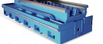
Restoring bed guides by planing
By planing, you can restore the guides, provided that the dimensions of the bed do not exceed the dimensions of the table of the longitudinal planing machine. The bed must be accurately installed on the machine table.
The bed to be repaired is fixed in the middle (approximately) part of the table of a well-calibrated planing machine. After this, check the parallelism of the base surface (the plane under the rail) to the movement of the table along the entire length, and the deviation from parallelism should not exceed 0.04 mm over a length of 1000 mm. The check is carried out with an indicator mounted in the machine support.
Next, a test planing of any of the horizontal surfaces is carried out until wear is eliminated, which is then checked for straightness with a control ruler and feeler gauge in order to determine the amount of their non-straightness caused by inaccuracy of the table movement and various other reasons. Having received the necessary data, attach the frame to the table with bolts, nuts and clamps. Wedges with a slope of 0°30' - 0°40' and a thickness of about 0.1 mm at the sharp end are placed under the base of the bed.
Using clamps in four sections A and B, the machine bed is deformed in the vertical plane by the amount of deviation from straightness found by test planing. If the deviation is directed towards the concavity and is equal to K mm, then bend the frame in the same direction by an amount of K + 0.02 mm and eliminate the wear of the guides by planing. When, at the end of planing, the bolts are loosened and the clamps and wedges are removed, the bed will spring and its guides will become straight. This will happen because during planing, a larger layer of metal was removed at the ends of the bed than in the middle. The deviation of the guides towards the convexity will be within the limits permitted by the technical requirements.
If the deviation from straightness is directed towards convexity, the frame is bent by an amount K - 0.02 mm. After removing it from the table, the guides, as in the previous case, will have a convexity permissible by technical requirements of up to 0.02 mm per 1000 mm of length.
Rice. 7. Diagram of bed deformation when installed for planing
Test planing of the guides is carried out once; the resulting value K of deviation from straightness is taken as a constant for subsequent repairs of frames of different models of similar length.
The methods for deforming the bed are as follows. To bend the bed in the middle part (see Fig. 93, a), the wedges are placed closer to its ends, and the clamps are closer to the middle in the places indicated by arrows A. To bend the bed in the middle part (Fig. 93, b), the clamps are placed closer to its edges, as shown by arrows B, and the wedges are placed closer to the middle. The required deflection or bending is obtained by tightening the bolts of the clamps and moving the wedges with light blows of a hammer *.
When tightening the bolts and adjusting the wedges, observe the indicator arrow readings. The measuring rod of the indicator must be brought to the place of maximum deflection of the frame - point O. The accuracy of the position of the frame is finally checked when fastening the bolts.
The described method of installing the bed being repaired on the planing machine table guarantees the proper straightness of its guides even in cases where the movement of the machine table deviates significantly from straightness. This operation is usually performed by a planer, and a repairman must know this and be able to control it.
It is recommended to install cutters for planing guides according to a template that has the same profile as the guides. The template is fixed on the machine table in front of the bed from the cutter approach side, taking into account the thickness of the chips removed during planing.
Making templates for all guide profiles is too expensive. Therefore, in some cases, cutters are installed directly along the profile of the guides using probes.
When planing the guide beds of lathes, proceed as follows: - the cutters are brought to a probe placed on the unworn part of the guides, where the headstock is attached; — the probe is pulled between the surface of the guides and the cutter, and it should pass under the influence of slight force; — the cutters are lowered to the depth of the metal layer removed during planing.
The bed guides should be planed with wide cutters with a fine-tuned blade. The use of cutters with a wide blade makes it easier to adjust the planer support along the guide profile and allows you to reduce the number of passes during planing.
Surfaces 1, 2, 3, 4, 6, 7,8 are processed by planing and up to the limit of their maximum wear; the surfaces, as a rule, are not planed, since, as indicated, they do not have wear.
The accuracy of guides repaired in the described manner fully meets the technical conditions for acceptance of machine tools. After planing, it is checked using a universal level bridge.
Restoring bed guides by grinding
The bed guides are ground on special grinding, longitudinal planing, or longitudinal milling machines equipped with special devices. And with such processing, the frame installed on the machine table is subjected to deformation. Grinding (both flat and prismatic guides) is carried out with the end of the cup grinding wheel and the periphery, including straight profile wheels. In this case, heating of the guides, which causes deformation of the frame, is not allowed.
Devices for grinding guide frames and tables are relatively inexpensive. They are divided into stationary and portable. Stationary ones include not only grinding heads, but also milling heads installed on longitudinal planing, longitudinal milling and other machines, usually on a caliper. Portable devices are used for grinding or milling the beds of metal-cutting machines without removing them from the foundation.
When using portable devices, you must first prepare a base for their installation. Typically, an unworn or slightly worn surface is used as a base, which is cleared of nicks and then checked for straightness (if required, scraping is also used). The use of portable devices is more economically profitable when the length of the machined bed exceeds 2.5 m. Stationary devices do not require preliminary preparation of the base surfaces, in addition, they are more reliable in operation than portable devices. However, they can only be used where appropriate equipment is available.
Rice. 8. Grinding with the end of a wheel: a - with a slope, - without a slope
Grinding is carried out with a cup wheel with a diameter of 100-175 mm at a speed of 30-40 m/s. The least heating of the bed and better removal of chips and dust is ensured when grinding with the end of a wheel and tilting the spindle axis by 1-3°; however, in this case the grinding quality decreases. That is why this method is used at the “roughing” stage, i.e. during preliminary grinding.
For finishing, the spindle and grinding wheel are positioned strictly perpendicular to the surface to be ground. The quality of grinding is high, but the conditions for chip removal deteriorate, which leads to heating of the bed. This forces grinding to be carried out at reduced conditions - with a cutting depth of no more than 0.01 mm.
The accuracy of setting the spindle perpendicular to the surface being processed is determined by the pattern on it formed as a result of crossing strokes. Non-crossing strokes are obtained when the circle is installed with an inclination to the surface being processed.
Portable devices are distinguished by the peculiarity that the accuracy of their processing of guides primarily depends on the accuracy of the installation base of the device. In this regard, as already indicated, the required accuracy of the base surfaces is first achieved, for which low-wear guides for the tailstock, easily restored by scraping, are usually chosen on a lathe. Longitudinal feed in portable devices is carried out by means of screws, bushing or roller chains.
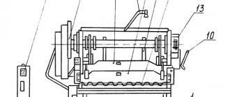
Rice. 9. Portable device for grinding guide frames: a - device in operation, - types of profiles processed using the device
A general idea of a portable device for grinding guide frames is given in Fig. 9, a. The device plate with its two replaceable guides, which are attached to it with screws, is installed on a lathe - on scraped-in guides for the tailstock. The latter can have any shape allowed by a set of interchangeable guides of the device. At the bottom of the plate there are spring-loaded stops with ball bearings and 5, which act as rollers. The device is moved along the frame manually. When grinding large beds, a chain drive can be used.
In case of significant and uneven wear of the guides, devices are used to mill them. However, after milling, the guides must either be scraped or ground. The longer the frame length, the more profitable it is to use portable devices.
In Fig. 9. b shows the types of profiles processed by a portable grinding device: - lathe bed; — bed of a longitudinal planing machine, 8, 9, — dovetail type guides, — combined shape.
Repair by scraping
Scraping of guides or scraping followed by lapping remains the most effective way to restore their geometric and technical accuracy. And now this method is often used, demonstrating excellent results in machine bed repair for many decades. First of all, it is necessary to examine the condition of the guides and determine the degree of their wear. The place where the wear is minimal is taken as the base level, and the measurement data is entered into a table, on the basis of which repairs will be made. In a lathe, the base surface is most often taken to be the location of the tailstock, which practically does not wear out during operation of the equipment. The method includes the following steps:
- installation of the machine bed on a rigid base (repair stand), the longitudinal and transverse position of the bed should be adjusted exactly in the horizontal plane using wedges, shoes or using jacks;
- after completion of the preparatory work, rough (preliminary) scraping is performed with a working scraper width of 20-25 mm, while maintaining a length of strokes on the surface of more than 10 mm and achieving 4-6 spots when checking paint in 25x25 mm squares. This achieves the breakdown of large spots into smaller ones;
- semi-finish scraping is performed with a 12-16 mm scraper, stroke length 5-10 mm until 8-15 spots per square are achieved;
- finishing (finishing) scraping is carried out with a scraper 5-10 mm wide and strokes 3-5 mm long to achieve 20-25 spots per square.
[Show slideshow]
Since the guides of the lathe bed are quite long, processing is carried out along the beacons, dividing the total length into sections. The first beacon is always the place of maximum production. At a distance less than the length of the straight edge from the first beacon, a second beacon is scraped, located in the same plane as the first. Then the entire surface between the beacons is scraped, followed by moving to the adjacent area. Periodically, apply a ruler with paint to assess the condition of the guides and the quality of work.
Watch the video of rough scraping
Non-hardened parts of lathe guides are subjected to this treatment; the method guarantees the achievement of high surface accuracy (0.002 mm per 1000 mm length). The tiny holes formed after scraping are able to hold the lubricant well and distribute it evenly. The quality of scraping depends entirely on the professionalism of the worker.
Eliminating scoring on guides using polymer materials
- home
- Articles
- Eliminating burrs on guides
2
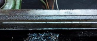
Another common defect that occurs during the operation of grinding machines is the appearance of scoring. The cause of this type of defect can be, for example, loss of lubricant during operation. Similar damage was found on the bed guides of the roll grinding machine mod. LUX5-05. A section 7200 mm long was damaged. Across the entire width of the guides, from 8 to 12 burrs up to 0.8 mm deep were recorded.
To apply the polymer material, the notches were pre-prepared: the V-shaped notch in cross-section was given a U-shape using a disk cutter. Surface preparation, filling of burrs with Moglais FL/P and formation of the working surface were carried out similarly to the operations described in the first case.
Similar damage was eliminated on the carriage guides using the multimetal-steel material (Diamant, Germany). The described types of repairs did not require dismantling the machine frame and were completed in a short time.
One of the most complex repairs carried out in recent years was the repair of a horizontal boring machine mod. 2A656F11. The machine received damage in the form of multiple scratches in the lower part of the bed guides at a length of 1500 mm and similar damage on the carriage guides. It was decided to restore the guides using polymer material. Another option - grinding six planes of guides over a length of 4000 mm - was not possible in the conditions of a metallurgical plant. Sending the machine to the manufacturing plant was unacceptable due to the high cost and the impossibility of removing the machine from the production process.
The initial stage was to restore the bed guides. The damaged areas were milled to a depth of 2.0 mm. The formation of the plane of the bed guides, installed horizontally, was carried out using the “multi-metal-steel” material and polished rulers. Particular attention was paid to ensuring contact of the rulers with the base surfaces after applying the material. For this purpose, specially designed traverses and screw clamps were used (for horizontal planes of the frame), as well as powerful clamps (for vertical planes of the frame).
The guide carriages were prepared for the next step. The milled grooves of all six guide planes (four horizontal and two lateral vertical) were degreased. The restoration was carried out using Moglais FL/P and Moglais-hart materials. Two vertical guides were restored by injecting a restoration compound with an injector into the gap between the ruler and the groove milled in the guide. The ruler was installed in advance and secured with clamps.
The final stage of forming 4 carriage guide planes was performed after applying the material to the milled grooves. The material was applied with 30% excess of the required volume. Then the bed was laid on the carriage and secured with special clamps. This operation was complicated by the uneven load on the carriage and the impossibility of installing it in a strictly horizontal position. In this regard, the carriage was mounted on a hinged device, which ensured a perfect fit. Thus, all 4 guides were formed by the bed guide planes in one installation. The required technological processing accuracy has been restored, there are no comments on the work.
Article parts: 2
Repair by grinding
It is not always possible to use planing or longitudinal milling machines for repairs due to the long length of the lathe bed. In this case, the bed guides are restored using a portable device with a grinding head, which is installed directly on the equipment bed.
Repairs can be made on site, without removing the machine from the foundation. This method ensures high repair accuracy, low surface roughness, and is also indispensable when processing hardened surfaces. This method is many times more productive than scraping, but experts still prefer finishing planing.
[Show slideshow]
Repair cost
| Type of work | Price |
| Spindle Prevention | 9,000 rub. |
| Troubleshooting clamping devices | 19,000 rub. |
| Burnout (damage) of the stator winding | 30,000 rub. |
| Replacing bearings with rotor balancing | 50,000 rub. |
| Replacing spindle sensors | 10,000 rub. |
| Maintenance | 10,000 rub. |
| Non-standard work | 10,000 rub. |
| Major renovation | 50,000 rub. |
| Modernization of machine tools | 30,000 rub. |
Our main specialization is machine repair
If your machine does not work, our specialist will arrive as soon as possible and fix it. Call and consult by phone: 8
Technologies
Thanks to the use of modern devices, we can more accurately identify faults. And we save your money on repairs
Ideas
If your machine does not break down as usual. We will send it to our technicians and they will solve any problem
Speed.
You need the machine to work as quickly as possible. Our desires coincide.
Read useful information:
Self-repair of the machine shaft and care for it
In the modern world, the use of complex equipment is associated with wear and tear. In particular, the shafts of various machines are subject to enormous loads due to the large volume of work, and sometimes due to the conditions in which they are operated. The article discusses the main causes of breakdowns, as well as methods of prevention and maintenance of equipment. Questions about repairs for various damage to machine shafts are also covered.
Further
Repair of the electrical part of the machine
The slightest malfunction of the electrical part of the machine can disrupt the plant’s work schedule. It is important to be able to identify the source of the problem and eliminate it.
Further
Spindle malfunctions and their elimination
In modern production, many CNC (computer numerical control) machines are used. Machines work continuously around the clock and, like any equipment, sometimes have malfunctions. One of the main elements of machine tools is the spindle. Let’s look at what breakdowns can occur during operation and whether they can be repaired yourself.
Further
Types of production machines, their setup and maintenance.
To work effectively with machine tools, you need to understand the types and purposes of machines, be able to carry out setup and independent maintenance. In this article we will analyze the main types of machines and general setup rules.
Further
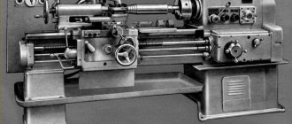
Lathe device
A classic lathe made in the USSR consists of the parts shown in the drawing:
Lathe device - front view
This figure does not show everything, only some parts, but this is enough for a basic understanding. The parts that are related to electrical are highlighted.
- 8 – handle for clutch and switching direction of spindle rotation. The important thing is that this handle acts on the zero stroke limit switch - while it is pressed, the machine will not turn on.
- 12 – Start and Stop buttons for controlling the main engine.
- 21 – non-latching button to turn on the high-speed motor (accelerated movement of the carriage).
- 24 – lighting lamp.
- 27 – direct connection ammeter, for monitoring the main motor current.
- 28 – toggle switch for turning on the engine of the coolant pump (coolant).
- 29 – power on indicator.
- 30 – power handle.