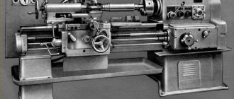
Repair by scraping
Scraping of guides or scraping followed by lapping remains the most effective way to restore their geometric and technical accuracy. And now this method is often used, demonstrating excellent results in machine bed repair for many decades. First of all, it is necessary to examine the condition of the guides and determine the degree of their wear. The place where the wear is minimal is taken as the base level, and the measurement data is entered into a table, on the basis of which repairs will be made. In a lathe, the base surface is most often taken to be the location of the tailstock, which practically does not wear out during operation of the equipment. The method includes the following steps:
- installation of the machine bed on a rigid base (repair stand), the longitudinal and transverse position of the bed should be adjusted exactly in the horizontal plane using wedges, shoes or using jacks;
- after completion of the preparatory work, rough (preliminary) scraping is performed with a working scraper width of 20-25 mm, while maintaining a length of strokes on the surface of more than 10 mm and achieving 4-6 spots when checking paint in 25x25 mm squares. This achieves the breakdown of large spots into smaller ones;
- semi-finish scraping is performed with a 12-16 mm scraper, stroke length 5-10 mm until 8-15 spots per square are achieved;
- finishing (finishing) scraping is carried out with a scraper 5-10 mm wide and strokes 3-5 mm long to achieve 20-25 spots per square.
Since the guides of the lathe bed are quite long, processing is carried out along the beacons, dividing the total length into sections. The first beacon is always the place of maximum production. At a distance less than the length of the straight edge from the first beacon, a second beacon is scraped, located in the same plane as the first. Then the entire surface between the beacons is scraped, followed by moving to the adjacent area. Periodically, apply a ruler with paint to assess the condition of the guides and the quality of work.
Watch the video of rough scraping
Non-hardened parts of lathe guides are subjected to this treatment; the method guarantees the achievement of high surface accuracy (0.002 mm per 1000 mm length). The tiny holes formed after scraping are able to hold the lubricant well and distribute it evenly. The quality of scraping depends entirely on the professionalism of the worker.
DIY repair
If any types of deformation appear on the surface of the guides, you can correct the damage yourself. There are several types of equipment repair for this purpose.
Repair by scraping is considered one of the effective ways to level the guide surface. This method of repairing breakdowns has been around since ancient times. This can be said to be an old-fashioned way of solving the problem. To do this, you must first examine the guides and identify the degree of wear. Where there is not much damage, it is considered the main level. This data should be entered into a table.
- The bed along with the guides should be placed on a hard, flat surface (preferably on a repair stand).
- Using wedges, a jack or shoes, the bed should be leveled to a clearly horizontal position.
- First, the so-called rough scraping is carried out:
- scraper width 20 – 25mm.,
- stroke length ≥10mm.
- The formation of about 4 - 6 spots in an area of 25 x 25 mm is allowed when checking for paint.
The next stage is semi-finish scraping:
- scraper width 12 – 16mm.,
- stroke length from 5 to 10mm;
- paint control 8 – 15 (25 x 25).
The last stage of scraping:
- scraper width 12 – 16mm.,
- stroke length from 5 to 10mm;
- paint control 8 – 15 (25 x 25).
Sanding – used for long beds. In this case, a portable grinding device is used. It is installed directly on the tool, secured and the machine is turned on. To do this, you do not need to remove the device from the foundation. And the accuracy is much higher than the previous type of repair. Although professionals still prefer scraping.
Repairs by planing are not as exhausting as scraping, and are much cheaper than sanding. But it is used when the depth of wear does not exceed 0.15 cm. For this, another machine (longitudinal planing) is used. To do this, the frame is removed from the foundation and secured to the planing device table.
The repair is carried out in several stages.
The first step is to make a test cut to create the main surface. To do this, find the deepest defect and cut it off until the damage is corrected.
The next stage is finishing planing. For this you need carbide cutters. Then they make two approaches until wear is eliminated, but for the last approach it is necessary to lower the cutter no lower than 0.05 mm.
After each approach, the cutter must be moistened with kerosene. And if the wear is more than 0.4 - 0.5 mm, it is subjected to rough planing.
Guide repair methods
The choice of method for repairing the guides of lathes (it is quite difficult to carry out such repairs yourself, without special equipment) depends on how badly these structural elements are worn, what hardness they have, how well technically equipped the repair team that will carry out this work is. difficult procedure.
Worn lathe bed guides
Bed guides that have undergone significant wear after long-term use can be restored in different ways: planing, milling, scraping (with or without lapping), pulling, grinding, rolling using special rollers. The most common methods used to overhaul a lathe bed include planing, scraping, and sanding.
The amount of wear on the guides can be determined only after all dirt and existing nicks have been removed from their surface. To determine the gaps present on these components of the lathe, apply a metal ruler to them and, using a feeler gauge, identify the most worn areas that require urgent repairs, taking measurements every 30–50 cm.
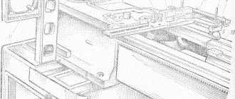
Checking the bed using a homemade device
Experienced specialists can identify the most worn areas of the bed guides using thin paper, the thickness of which does not exceed 0.02 mm. Such paper is placed on the lathe components in question and pressed against them with a metal ruler. In those places where the guides have not undergone serious wear, the paper does not pull out from under the ruler, but breaks off along its edge.
Determination of the least worn areas of the bed
To perform scraping, which is carried out as part of a major overhaul, the equipment frame is installed on a rigid base, checking the position of its elements in the longitudinal and transverse directions and, if necessary, using shoes and wedges to adjust its location.
When checking the condition of the bed guides and the degree of their wear, those parts that are located under the tailstock are used as reference surfaces (they are the ones that are subject to the least wear during operation). After each scraping stage, these lathe components are checked for parallelism and curvature.
Grinding bed guides in garage conditions
Grinding the bed guides, compared to the scraping operation, is characterized by higher productivity, but it is not advisable to use this method when restoring unhardened components.
In order for the lathe bed to be polished efficiently, all nicks and burrs must be thoroughly cleaned. Then the frame for repair is fixed on the work table of the longitudinal planing machine, ensuring the parallelism of its surfaces and the direction of its movement. In addition, using a level that is installed on the tailstock bridge, check the curvature of the guides. Only after this they begin to grind these nodes.
As before grinding, before finishing planing, the frame should first be cleaned of existing nicks and secured to the working surface of the longitudinal planing machine, checking that its elements are parallel to the direction of its movement.
Read also: How to connect a gas cylinder through a reducer
When using this repair method, the bed guides are processed with a cutter in 3–4 passes, after which their parallelism, straightness and twisting are checked. If, after processing, all the geometric parameters of the units being repaired meet the requirements, the frame is detached from the surface of the working table of the longitudinal planing equipment.
Videos of such restoration operations show that it is almost impossible to do them yourself without special equipment for repairs.
Repair by planing
This method is less tedious than scraping and less expensive sanding. For example, the average repair time for machine guides is:
- scraping: about 35 hours;
- grinding with a special abrasive head: 8-10 hours;
- finishing planing: 4-5 hours.
If wear is more than 0.15 mm, manual scraping is replaced by mechanical processing on a longitudinal planing machine with a centralized method of organizing repairs in a repair shop or at a specialized enterprise. The reason is simple: you will have to remove the frame from the foundation and install and align it on the rigid table of the planing machine.
Planing bed guides
At the first stage, test planing is carried out once to obtain a base surface, which will make it possible to determine deviations along the entire length of the bed. To do this, alternately bring the cutter to the most worn surfaces and remove the metal layer until the wear is eliminated. Finish planing is performed in at least two finishing passes with wide carbide cutters. The last pass is performed with a cutting depth of less than 0.05 mm, constantly wetting the cutter and the surface of the guides with kerosene. When wear exceeds 0.4-0.5 mm, the guides are subjected to rough and fine planing. The main disadvantage of this repair method is the considerable time it takes to dismantle the bed, transport, install the bed on the planer table, align and remove the restored bed.
When cutting the flat prismatic surface of the guides, small metal particles of various sizes and shapes are torn out from the solid frame. Furrows and grooves appear on the surface, forming a rough surface. Therefore, sometimes after machining it is impossible to do without scraping or vibration rolling. This increases the strength of the guides due to plastic deformation (changes in the structure of the material). Vibration rolling achieves smoothing of micro-roughness and irregularities by translational movement along and across the axis with specially treated balls or rollers.
Repairing lathe guides using one of the described methods is an element of complex work related to restoring the full functionality and accuracy of metal-cutting equipment. But we should not forget that the quality of the repair, with a minimum period of time for its completion, significantly depends on the degree of preparation of the machine for repair and the qualifications of the mechanic.
Tell me about scraping the bed. - Lathes
Finally I got around to my 16b05p lathe and decided to scrape off all the surfaces.
Of the tools, there are two rulers, one SD-1000 and a triangular 55 deg 400 mm, an indicator stand and a level 0.05 mm\m.
I started by scraping off the guides of the guard, brought them into one plane, controlling the propeller level, and scraped the guard to the guides. Regarding the platform, the ZB brought out all the other planes under the caliper, and the planes at the beginning and at the end, which the caliper entered extremely rarely or in that place it did not work at all, relative to the platform of the ZB, the readings were the same, only wear was visible in the middle and most strongly closer to the cartridge.
After that, I felt the urge to check the tailstock guides again, if you check the propeller, everything is as it was, the level is at zero or very slightly deviates literally by 1/4 divisions, but if the level is set in the direction of movement of the rear wheel, then if you take the start of movement as 0, then to the other side the level will go by 4-4.5 divisions, while there is a pattern, in the middle it will go by 2 divisions and if you divide the entire frame into 4-5 segments, then on each segment it will clearly go by 1 division, please tell me how can this be? Maybe this is normal or does no one measure frames like this?
I have attached a video of the propeller test and 3 photos when the level is in the direction of movement with a stop in the middle.
Thank you all. Modified on September 7, 2022 by Ace Ventura www.chipmaker.ru
Types of failures of lathes
In most cases, the structure of lathes is the same:
- bed;
- spindles;
- working grandmother.
In this case, scraping of workpieces is usually carried out in a horizontal plane. If we analyze screw-cutting lathes, they differ from simple ones in that they have front and rear working headstocks, a support, a bed with an extension and a feed box. The following malfunctions occur in the equipment:
- Based on practice, the spindle speed control module breaks first. Tapered roller bearings, which are used in many machines, are subject to the greatest degree of wear. From time to time, adjustment and replacement of bearings is necessary, which directly depends on the lubrication system and type of machine.
- The next most common breakdown is a malfunction of the caliper locking holder. In this case, the part being processed moves unevenly, both in the transverse and longitudinal directions.
All lathes vary in size, design and type of workpieces. There are semi-automatic and automatic devices. The latter, as a rule, work much longer, since when feeding manually, the size of the head and the degree of its turning are often not calculated correctly.
Repair by grinding
It is not always possible to use planing or longitudinal milling machines for repairs due to the long length of the lathe bed. In this case, the bed guides are restored using a portable device with a grinding head, which is installed directly on the equipment bed.
Repairs can be made on site, without removing the machine from the foundation. This method ensures high repair accuracy, low surface roughness, and is also indispensable when processing hardened surfaces. This method is many times more productive than scraping, but experts still prefer finishing planing.
Types of repairs
Repair work is carried out in order to maintain the operational characteristics of turning equipment and is of two types: planned and unscheduled. The first ones are carried out only on the basis of preventive maintenance schedules. For 16K25, four types of work are provided, including inspection and three types of repairs:
- small;
- average;
- capital.
According to clause 17.2 of the “Operating Manual” of the 16K20 lathe, its turnaround period (working time before the first overhaul), subject to compliance with the manufacturer’s operational requirements, is 10 years with two-shift operation. During this period, six scheduled inspections 16K20, four minor repairs, one medium (in the middle of the period) and one major (at the end of the period) must be performed.
The need for unscheduled repair work usually arises when the permissible parameters of equipment suddenly decrease or fail. This usually happens when the manufacturer’s specifications for the operation and maintenance of turning equipment are not met. At production enterprises, all types of work are carried out according to maintenance schedules by qualified personnel of specialized repair departments. In small enterprises, repairs to a lathe are carried out with their own hands as problems arise with its accuracy and performance.
Small repairs
This type of repair work is carried out both according to the approved nomenclature and according to the results of observations of turning equipment during shift and periodic maintenance. Its purpose is to ensure the operation of turning equipment until the next scheduled repair.
According to clause 17.3.3 of the “Operating Manual” of the 16K20 lathe, during minor repairs the following types of work are mandatory:
- identifying faults for elimination during subsequent scheduled repairs;
- measurements of equipment geometry for certified accuracy;
- idle tests;
- noise and temperature tests;
- checking the accuracy and purity of processing.
The rest of the work from the list given in the Manual is carried out only if necessary, depending on the condition of the equipment. Based on the results of minor repairs, a statement of the condition of machine parts is compiled for inclusion in the work that follows the scheduled maintenance work.
Medium renovation
This type of repair work includes work according to the list of recommendations for minor repairs, as well as partial disassembly of the turning 16K20, during which the functionality of the main mechanisms and assemblies is restored. Such repairs for the 16K20 screw-cutting lathe are carried out according to the list given in paragraph 17.3.4 of the “Operating Manual”.
During an average repair, the accuracy is checked before and after disassembling the turning equipment, the spindle rigidity is checked, and the wear of the friction surfaces is measured before and after their restoration. The average repair of a lathe is performed in the middle of the overhaul period. Its goal is to restore the service life of turning equipment to such a level that the machine can operate until a major overhaul.
Major renovation
According to clause 17.3.2. In the “Operating Manual”, a major overhaul of the 16K20 lathe is preceded by an inspection of the condition of the machine equipment. During the inspection, inspection data from previous repair work is checked, lists of parts for restoration and replacement are determined, and working drawings are produced for ordering replacement parts.
Overhaul of machine 16K20
During major repairs, before complete disassembly, the accuracy of 16K20 and the degree of wear of the friction surfaces will be checked.
After complete dismantling of all mechanisms, each part is cleaned, after which they are inspected and compared with the defective list. The overhaul involves the restoration of all passport characteristics of 16K20. Therefore, lathes after a high-quality overhaul have the same parameters as new turning equipment, and their overhaul period is also ten years.
Download the passport (operating instructions) of the lathe 16K20
Repair cost
| Type of work | Price |
| Spindle Prevention | 9,000 rub. |
| Troubleshooting clamping devices | 19,000 rub. |
| Burnout (damage) of the stator winding | 30,000 rub. |
| Replacing bearings with rotor balancing | 50,000 rub. |
| Replacing spindle sensors | 10,000 rub. |
| Maintenance | 10,000 rub. |
| Non-standard work | 10,000 rub. |
| Major renovation | 50,000 rub. |
| Modernization of machine tools | 30,000 rub. |
Our main specialization is machine repair
If your machine does not work, our specialist will arrive as soon as possible and fix it. Call and consult by phone: 8
- Thanks to the use of modern devices, we can more accurately identify faults. And we save your money on repairs
- If your machine does not break down as usual. We will send it to our technicians and they will solve any problem
Read useful information:
Machine support repair
In the modern world, various machines are widely used, because... they allow you to perform many operations. This unit consists of many parts, where the main role is played by the machine support. And it often happens that the work of the tool freezes due to the breakdown of the caliper or other parts.
Further
Spindle malfunctions and their elimination
In modern production, many CNC (computer numerical control) machines are used. Machines work continuously around the clock and, like any equipment, sometimes have malfunctions. One of the main elements of machine tools is the spindle. Let’s look at what breakdowns can occur during operation and whether they can be repaired yourself.
Further
Repair of metalworking machines
Further
Overhaul of machines
Not one unit can work forever. To restore the functionality of turning equipment, they often resort to major repairs. It is difficult to carry out this process on your own, so it is worth contacting a company that specializes in repairing these units.
Further
Turret machine repair
In case of significant breakdowns of the turret machine, a lot of difficulties can arise. In the article you can learn about the types of such equipment, as well as how to carry out repairs yourself and how much the help of specialists will cost.
Further
When concluding a long-term service agreement, you receive a discount of up to 20%. Don't forget, we have a guarantee on all types of work.
- engineer - mechanic
- CNC programmer
- Service engineer
- Electrician
- Electronics engineer
- Locksmith - repairman
Types and features of repair work
The classification of all repair work carried out is carried out on the basis of a system of planned preventive maintenance (PPR). This complex includes:
- technical (overhaul) maintenance – ensures the operation of the machine between repairs. Maintenance involves caring for the equipment in use and minor repairs. Can be performed by machine operators and mechanics on duty;
- current repairs are carried out during the operation of the equipment to ensure its guaranteed performance. During the repair process, parts of the machine are replaced or restored, as well as the necessary adjustments and adjustments;
- major repairs - carried out to restore the serviceability of equipment. When performing a major overhaul, it is possible to replace the main components of the machine;
- Unforeseen breakdowns and emergencies are eliminated during unscheduled repairs. In this case, only damaged elements are replaced or restored.
Preparatory work
Before starting repair work, it is necessary to identify and determine all faults. To do this, the machine must be carefully inspected, checked for accuracy, read the entries in the fault logs, and assess the scope of repairs. It is necessary to study the structure of the machine by reading the drawings and technical data sheet.
It is important to correctly determine the order of disassembling the mechanisms and allocate a suitable place for this. We clean the machine from dust and technical liquids and prepare the tools necessary for repairs
The last step is to turn off the power to the equipment and post a warning sign.
Small
Minor repairs are characterized by the replacement or restoration of a small number of worn parts or components. When performing minor repairs, the machine is checked for accuracy and cleanliness of processing, bearings are adjusted or changed, lead screws are cleaned, and worn fastening elements are replaced. If necessary, repair the coolant and lubrication supply system.
Average
During the average repair of a lathe, the unit components are disassembled, several components or mechanisms are replaced or restored, guides are polished, and adjustments and tests are performed under load. When carrying out mid-term repairs, a List of Defects is compiled.
Capital
The most complex and most expensive type of planned repair. Includes a complete disassembly of all components and assemblies of the machine with recording of noticed faults and deviations in the defect list, complete repair of the tailstock and spindle, replacement or restoration of all faulty units. As part of the overhaul, technical modernization of equipment may also take place in order to increase productivity and reduce defects.
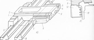
Wedge restoration
If the wedges are worn out a lot, repair usually comes down to their complete replacement, which is associated with additional costs of metal and time spent on making new wedges.
Repair experience using new technology shows that all wedges, regardless of their wear, can be restored. The new repair technology is based on the use of styracrylic and appropriate preparation of wedges for pouring.
Experience shows that the labor intensity of repairing wedges using the proposed technology is reduced by approximately 35%, while manual scraping work associated with adjusting the wedges in place is almost completely eliminated.
The technological process for restoring wedges with styracrylic (Fig. 72) is presented in table. 12.
Schedule and composition of repair and maintenance work
When the machine operates under normal operating conditions and compliance with all operating and maintenance rules specified in this manual, the overhaul cycle (service life before major repairs during two-shift operation) is (mainly) at least 9 years when processing steel (mainly), and at least 8 years for cast iron years. Maintenance and repair work is recommended to be carried out according to the repair work schedule (Fig. 39).
Machine inspection
- External inspection of the machine (without disassembling to identify defects) of the condition and operation of the machine as a whole and by components;
- Inspection and check of the condition of the main movement and feed drive mechanisms;
- Adjusting the table lead screw clearances;
- Spindle bearing adjustment;
- Checking the operation of speed and feed switching mechanisms;
- Regulation of the mechanisms for switching on cam clutches and feeds and the high-speed friction clutch;
- Adjustment of table wedges, slides, console and trunk;
- Inspection of guides, cleaning of nicks and burrs;
- Tightening loose fasteners;
- Checking the operation of the limiting cams;
- Checking the condition and minor repairs of cooling and lubrication systems;
- Checking the condition and repairing protective devices;
- Identification of parts that require replacement during the next repair (starting with the second minor repair);
Small machine repair
- Partial disassembly of components;
- Flushing all components;
- Adjustment or replacement of rolling bearings;
- Cleaning burrs and nicks on gear teeth, crackers and shift forks;
- Replacement and addition of friction discs of the high-speed clutch (starting from the second repair);
- Scraping and cleaning of wedges and strips;
- Cleaning the lead screws and replacing worn nuts;
- Cleaning nicks and burrs on the guides and working surface of the table;
- Replacing worn and broken fasteners
- Checking and adjusting the mechanisms for switching on speeds and feeds;
- Repair of lubrication and cooling systems;
- Testing the machine at idle speed, checking for noise, heating and accuracy of the workpiece.
Average machine repair
- Unit disassembly of the machine;
- Flushing all components;
- Inspection of parts of disassembled units;
- Drawing up a list of defects;
- Adjusting or replacing spindle bearings;
- Replacement or restoration of spline shafts;
- Replacement of worn bushings and bearings;
- Replacement of discs and fastener clutch parts;
- Replacement of worn gears;
- Restoring or replacing worn lead screws and nuts;
- Scraping or replacing adjusting wedges;
- Repair of pumps and fittings of lubrication and cooling systems;
- Correction by scraping or grinding the surfaces of the guides if their wear exceeds the permissible level;
- Painting the external surfaces of the machine;
- Running in the machine at idle (at all speeds and feeds) with checking for noise and heating;
- Checking the machine for accuracy and rigidity according to GOST 17734-72.
Overhaul of the machine
Major repairs are carried out with complete disassembly of all components of the machine, based on the results of which a defective estimate sheet must be drawn up. As a result of the repair, all worn components and parts of the machine must be restored or replaced, and its original accuracy, rigidity and power must be restored. The nature and scope of work for this type of repair are determined for specific operating conditions by a unified system of scheduled preventive maintenance.
Pekelis G.D., Gelberg B.T. L., "Mechanical Engineering". 1970
Varieties
To bore the jaws of a lathe chuck, it is necessary to choose the optimal method for a particular type. Several types of cams are produced, each of which has design features.
Direct
This type of cam is designed to clamp a workpiece with a shaft on the outside and for a workpiece with a hole on the inside. The cams are directly located on top and grip the part.
Reverse
Necessary for clamping the workpiece from the outside. Used for processing hollow blanks so that there is something to cling to.
Invoices
This is a composite version of the cartridge, which is made of non-ferrous metal or stainless steel. Used when working with large-scale projects
This variation is used when working with workpieces of large diameter, and it does not matter whether they are long or short
Prefabricated
A metal cam in this type is mounted on a steel rail. Alloy steel is used, and the cam teeth are ground, hardened and carburized.
Parameters of cutters for their use in equipment
The key parameters of the technological process of this type of activity depend on the selected attachment (cutter). The angle of its rotation affects not only the shape given when turning and cutting the workpiece, but also the temperature. The main task of the master is to monitor the effective removal of temperature from the metal, since when heated strongly, parts can lose their primary geometric shape. Heating of workpieces depends on their size and metal density. For cast iron, for example, it is not recommended to set the main angle of the cutter to 60 degrees or more during the first operation, since a strong impact on the material will heat it to a critical temperature. The optimal parameter in such conditions would be an angle of 45 degrees, followed by its increase to the desired value.
There are two main types of cutters for boring metal workpieces:
- Roughing cutters;
- Finishing cutters.
The first option is necessary for primary boring processes, when a significant part of the metal is removed. The structure and surface of the cutter does not allow achieving an ideal smooth surface. Such nozzles have high mechanical strength, as they are subject to high loads due to the large volume of metal removed (this leads to heating and other factors). Despite the initial boring, maximum dimensional accuracy is achieved during this operation.
Finishing cutters are designed for precise filigree boring and giving the exact dimensions specified in the technical specifications. While “rough” bits can leave a rough texture on the workpiece, finishing cutters completely smooth out the surface, removing any irregularities and chip elements even on the densest metals and alloys. The shape of the cutters is designed in such a way that during the removal process the chips do not fall into the moving mechanisms, but are brought out into specially designated containers under the chuck and spindle.
Typical faults
Most often, lathes deteriorate the cleanliness of the machined surface. This occurs due to wear of the spindle group bearings. The cleanliness and precision of processing is also affected by the play in the transverse feed of the caliper. Very often problems arise with the inclusion of working feeds and speeds. This occurs due to wear of bearings, spacer rings and gear forks. Such malfunctions are manifested by difficulty turning on feeds or speeds and self-switching off (“knocking out”) during operation. During intensive use, lathes experience many other equally serious breakdowns.
If you need to repair your lathe, please contact us and we will try to help you. You will find the machine repair algorithm in the REPAIRS section.
This is interesting: Checking lathes for accuracy - GOST, video
Wedge restoration
If the wedges are worn out a lot, repair usually comes down to their complete replacement, which is associated with additional costs of metal and time spent on making new wedges.
Repair experience using new technology shows that all wedges, regardless of their wear, can be restored. The new repair technology is based on the use of styracrylic and appropriate preparation of wedges for pouring.
Experience shows that the labor intensity of repairing wedges using the proposed technology is reduced by approximately 35%, while manual scraping work associated with adjusting the wedges in place is almost completely eliminated.
The technological process for restoring wedges with styracrylic (Fig. 72) is presented in table. 12.
Schedule and composition of repair and maintenance work
When the machine operates under normal operating conditions and compliance with all operating and maintenance rules specified in this manual, the overhaul cycle (service life before major repairs during two-shift operation) is (mainly) at least 9 years when processing steel (mainly), and at least 8 years for cast iron years. Maintenance and repair work is recommended to be carried out according to the repair work schedule (Fig. 39).
Machine inspection
- External inspection of the machine (without disassembling to identify defects) of the condition and operation of the machine as a whole and by components;
- Inspection and check of the condition of the main movement and feed drive mechanisms;
- Adjusting the table lead screw clearances;
- Spindle bearing adjustment;
- Checking the operation of speed and feed switching mechanisms;
- Regulation of the mechanisms for switching on cam clutches and feeds and the high-speed friction clutch;
- Adjustment of table wedges, slides, console and trunk;
- Inspection of guides, cleaning of nicks and burrs;
- Tightening loose fasteners;
- Checking the operation of the limiting cams;
- Checking the condition and minor repairs of cooling and lubrication systems;
- Checking the condition and repairing protective devices;
- Identification of parts that require replacement during the next repair (starting with the second minor repair);
Small machine repair
- Partial disassembly of components;
- Flushing all components;
- Adjustment or replacement of rolling bearings;
- Cleaning burrs and nicks on gear teeth, crackers and shift forks;
- Replacement and addition of friction discs of the high-speed clutch (starting from the second repair);
- Scraping and cleaning of wedges and strips;
- Cleaning the lead screws and replacing worn nuts;
- Cleaning nicks and burrs on the guides and working surface of the table;
- Replacing worn and broken fasteners
- Checking and adjusting the mechanisms for switching on speeds and feeds;
- Repair of lubrication and cooling systems;
- Testing the machine at idle speed, checking for noise, heating and accuracy of the workpiece.
Repair by scraping
Scraping of guides or scraping followed by lapping remains the most effective way to restore their geometric and technical accuracy. And now this method is often used, demonstrating excellent results in machine bed repair for many decades. First of all, it is necessary to examine the condition of the guides and determine the degree of their wear. The place where the wear is minimal is taken as the base level, and the measurement data is entered into a table, on the basis of which repairs will be made. In a lathe, the base surface is most often taken to be the location of the tailstock, which practically does not wear out during operation of the equipment. The method includes the following steps:
- installation of the machine bed on a rigid base (repair stand), the longitudinal and transverse position of the bed should be adjusted exactly in the horizontal plane using wedges, shoes or using jacks;
- after completion of the preparatory work, rough (preliminary) scraping is performed with a working scraper width of 20-25 mm, while maintaining a length of strokes on the surface of more than 10 mm and achieving 4-6 spots when checking paint in 25x25 mm squares. This achieves the breakdown of large spots into smaller ones;
- semi-finish scraping is performed with a 12-16 mm scraper, stroke length 5-10 mm until 8-15 spots per square are achieved;
- finishing (finishing) scraping is carried out with a scraper 5-10 mm wide and strokes 3-5 mm long to achieve 20-25 spots per square.
Repair of tailstock and headstock
Repair of the tailstock of the 16K20 machine begins with leveling the surfaces of the tailstock body, which mate with the guides of the plate. In this case, grinding and scraping methods are used.
At the next stage, the hole in the tailstock housing for the quill is repaired by boring on a boring machine and pressing in the bushing. The holes in the bushing are bored on a boring machine or on a machine being repaired using a boring bar.
As for the gearbox (headstock) and feedbox, they have quite complex kinematic diagrams. That is why the disassembly process requires the master to know the design features of the machine, the sequence of dismantling parts and assemblies, the locations of retaining rings, keys and other fixing elements.
IMPULS LLC specialists will conduct a free preliminary diagnostic of your equipment, an application for which can be submitted directly on the company’s website. We have all the necessary resources to perform high-quality repairs of machine tools and other industrial equipment of any complexity.
Russian screw-cutting lathes from the manufacturing plant RSPK Ryazan
- PHOENIX LLC, part of the RSPC Group of Companies, performs work on grinding guide frames on German longitudinal grinding machines.
- You can obtain information on grinding issues by calling or emailing:
- The policy of our company is aimed at dialogue with partners to reduce the time required to agree on production issues and the cost of work, as well as to accurately and high-quality execution of technical specifications in a short time.
- We carry out grinding of beds of various types of machines:
- guides for lathe beds with RMC up to 6 meters (1M63, 1M65, 16K20, 16M30, 1A983, etc.);
- guides for milling machine beds (6T13, 6K81, 6T83, etc.);
- guides for grinding machine beds (3L722, 3B724, etc.);
- carriage groups, consoles, racks, tables.
- The average time for completion of work is five working days.
Maximum parameters of processed products:
- Maximum grinding length, mm - 8590
- Table width, mm - 1800
- Passage between racks, mm - 2020
- Grinding height, mm - 1580
- The largest weight of the processed product, kg - 12500
PHOENIX LLC is ready to carry out work on grinding guides of any parts that allow us to fulfill the technical capabilities of our equipment.
During the operation of any machine, all its parts are subject to wear, including the bed. Wear of the frame – formation of cracks, level changes, etc. extremely strongly affects the quality of products manufactured on this machine. Therefore, the bed, carriage, racks, consoles and some other elements of machine tools need to periodically restore the geometry by grinding the guides.
Grinding the bed guides, also known as grinding the lathe bed, occupies a special place. It must be performed with the highest precision. We are pleased to inform you that now PHOENIX LLC provides various bed grinding services in Ryazan.
Prices for grinding bed guides
Prices for grinding beds, carriage groups, racks, etc. >>
Quality control when grinding beds
We carefully monitor the quality of all services we provide. Sanding beds was no exception. Once a week, the frames are selectively checked for geometry using an autocollimator. Also, if necessary, the grinding quality is checked for roughness using a Hommel-Etamic T1000 profilometer.
Photo of the grinding process on a 4 meter Waldrich Coburg machine and its results
The lathe bed is used for mounting components used on the machine. The frame is made of cast iron. The result is a massive, strong and durable structure, but it is the bed that is subject to the greatest wear during operation of the machine. This affects the accuracy of the parts produced on this machine.
The work of grinding the bed guides restores the geometric characteristics of the machine, and also eliminates burrs, nicks, complex damage and other defects. The bed is installed on the table and aligned using an indicator head. The degree of wear and straightness of the guides are assessed. After which the grinding process itself begins.
What is turning?
The technological process of turning consists of reducing the diameter of the workpiece using a cutter, which is equipped with a special cutting edge.
Due to the rotation of the workpiece, the cutting process occurs; feed and lateral movement are carried out by the cutter.
Thanks to these three components: rotation, feed, movement, it is possible to influence the amount of material removal; the quality of the machined surface, the shape of the chips, etc. also depend on this.
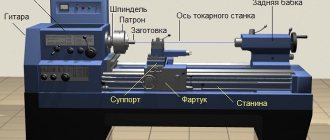
Basic elements of a lathe:
These elements are the main ones; depending on the modifications, you can get centering, turret lathe, multi-cutting and other machines that must undergo mandatory maintenance.
Technical characteristics of the machine 16K20
The 16K20 screw-cutting lathe is designed for finishing and rough machining of parts of rotating bodies made of non-ferrous and ferrous metal. It is used to perform various turning operations with straight and stepped profiles, drilling, boring, reaming, countersinking, trimming ends, turning grooves, cutting various types of threads.
Processing of workpieces on a 16K20 screw-cutting lathe can be carried out in a chuck or in centers. Screw-cutting lathes 16K20 are used in single and small-scale production.
| Technical characteristics of the machine 16K20 | |
| Largest processing diameter above the bed, mm | 400 |
| Largest machining diameter above the support, mm | 220 |
| Distance between centers (RMC), mm | 710 / 1000 / 1500 |
| Workpiece weight, kg | 1300 |
| Accuracy class (GOST 8-82) | N(P) |
| Spindle hole diameter, mm | 55 |
| Spindle inner taper | M6 |
| Spindle end | D6 |
| Maximum torque, Nm | 1000 |
| Spindle rotation speed in forward direction, rpm: | 12,5 – 1600 |
| Spindle rotation speed in reverse direction, rpm: | 19,0 – 1900 |
| Number of straight spindle speeds | 22 |
| Number of spindle reverse speeds | 11 |
| Cutter holder section, mm | 25 x 25 |
| Longitudinal carriage movement, mm | 950 / 1250 |
| Transverse movement of the carriage, mm | 219 |
| Range of longitudinal working feeds, mm/min | 0,05 – 2,8 |
| Range of transverse working feeds, mm/min | 0,025 – 1,4 |
| Number of longitudinal feeds | 42 |
| Number of cross feeds | 42 |
| Metric thread pitch range, mm | 0,5 — 112 |
| Range of inch thread pitches, threads per inch | 56 – 0,5 |
| Modular thread pitch range, module | 0,5 — 112 |
| Pitch thread pitch range, diametric pitch | 56 – 0,5 |
| Quill hole cone | Morse 5 |
| Quill stroke, mm | 150 |
| Main engine power, kW | 11 |
| Overall dimensions, mm: | |
| length | 2795 / 3195 |
| width | 1190 |
| height | 1500 |
| Machine weight, kg | 3005 / 3225 |
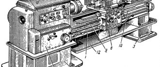
Lathe support device
General view of the caliper assembly with apron
Screw-cutting lathe support
Universal lathe support
The support of a universal lathe is designed to move a cutter fixed in a tool holder along the spindle axis, across the spindle axis and at an angle to the spindle axis.
The machine support has a cross design and consists of three main moving units - the support carriage, the cross slide of the support, and the cutting slide. In the technical literature, these units are called differently, for example, the caliper carriage may be called lower slide, longitudinal slide, longitudinal carriage. In our description we will adhere to the terminology from the Operating Manual for the 1k62 machine.
The caliper consists of the following main parts (Fig. 13):
- Carriage for longitudinal movement of the caliper along the guides (longitudinal slide, lower slide)
- Machine bed
- Cross slide (cross carriage)
- Cutter slide (top slide, rotary slide)
- Cross carriage feed screw
- Backlash-free detachable nut
- Cross carriage manual feed handle
- Gear for mechanical feed of cross carriage
- Rotary plate
- Four-position tool holder
In the circular guides of the transverse carriage 3 there is a rotary plate 9, in the guides of which the cutting slide 4 with a four-position tool holder 10 moves. This design allows you to install and bolt the rotary plate with the cutting slide at any angle to the spindle axis. When turning the handle 11 counterclockwise, the tool holder 10 is raised by the spring 12 - one of its lower holes comes off the clamp. After fixing the tool holder in the new position, it is clamped by turning handle 11 in the opposite direction.
The apron mechanism is located in a housing screwed to the caliper carriage (Fig. 14). Worm wheel 3 rotates from the running shaft through a series of gears. Rotation from shaft I is transmitted by the gears of shafts II and III. These shafts are equipped with couplings 2, 11, 4 and 10 with end teeth, which activate the movement of the caliper in one of four directions. The longitudinal movement of the caliper is carried out by rack wheel 1, and the transverse movement is carried out by a screw (not shown in Fig. 14), rotating from a gear wheel 5. Handle 8 serves to control the nut 7 of the lead screw 6. The shaft with cams 9 locks the lead screw and the lead shaft, so that it is impossible to turn on the caliper feed from them at the same time.
Photo of the cross slide and caliper carriage
Caliper carriage
The support carriage (lower slide, longitudinal slide) moves along the frame guides along the spindle axis. The carriage is driven both manually and mechanically using a feed mechanism. The movement of the carriage is transmitted using an apron rigidly fixed to the carriage. The carriage can be clamped to the bed with a clamping bar and screw for heavy cross-cutting work.
The apron contains mechanisms and transmissions designed to convert the rotational movement of the lead roll and lead screw into the rectilinear translational movement of the caliper carriage, longitudinal and transverse slides. The apron is rigidly attached to the caliper carriage.
In the upper part of the carriage, perpendicular to the spindle axis, there are dovetail-shaped guides for installing the transverse slide of the caliper.
Basic parameters for moving the support carriage for the 1k62 machine:
- The greatest longitudinal movement of the caliper by hand using the handwheel .. 640 mm, 930 mm, 1330 mm for RMC 750, 1000, 1500
- Maximum longitudinal movement of the caliper along the running shaft .. 640 mm, 930 mm, 1330 mm for RMC 750, 1000, 1500
- Maximum longitudinal movement of the caliper along the lead screw .. 640 mm, 930 mm, 1330 mm for RMC 750, 1000, 1500
- Moving the carriage one division of the dial .. 1 mm