In mechanical engineering, the share of lathes is up to 70% of metal-cutting equipment. Many parts are made on it. Turning is characterized by rapid rotation of the workpiece and a cutter fixed motionless on a support, moving along or across the axis of the rotating part. The result is cylindrical and conical parts.
Turning
Processing Features
The turning process on a lathe is a simultaneous rotational movement of the workpiece in a horizontal plane with the translational movement of the tool feed, which removes a certain layer of metal in one pass along the machined surface. During the processing process, the workpiece is clamped by the edge of the cutter, and the cutting tool overcomes the friction force and removes a given thickness of the metal layer.
A special feature of the lathe is the possibility of various combinations of two types of movement and the installation of various types of cutters, drills and other tools. This allows you to process cylindrical, shaped, conical and other surfaces, cut threads, drill internal holes and perform other metal-cutting operations. Turning can be used to produce nuts, bolts, couplings, pulleys, shafts and other parts.
Main turning capabilities:
- Turning of cylindrical, conical and shaped surfaces.
- Grooving.
- Threading
- Cutting parts and workpieces.
- Drilling internal holes.
- Reaming and countersinking of holes.
To accurately perform turning, measuring tools of various types and precision are used. These are calipers, micrometers, internal gauges, limit gauges, rulers, etc. With their help, the relative position of various surfaces is monitored, and the dimensions and shape of the part are determined.
Equipment and tools
On lathes, workpieces are processed by rotating them around a horizontal and vertical axis. The main tool used is cutters. All turning equipment is marked with the number “1” and is divided into 9 types, taking into account the features of the device.
The tool rotates using a special device on the caliper. Grinding and milling work is performed on a lathe.
Types of lathes
There are main types of lathes used in production:
- screw-cutting lathe;
- turning-turret;
- rotary turning;
- turning and grinding;
- lobotocar.
Screw-cutting lathes are the most widely used. They process long parts such as shafts and short cylindrical ones.
Carousels are used for the manufacture of bushings, rings and other large parts whose diameter is greater than their height.
Classification of incisors
According to the location of the cutting edge and the direction of movement of the caliper, cutters are divided into two types:
- rights;
- left.
According to the shape of the working part:
- straight - the working part and the body have common lateral surfaces;
- bent - the cutting edge protrudes beyond the plane of the body and has a variable cross-section.
For external processing, types of cutters are used, named after the operations they perform:
- checkpoints;
- groove;
- shaped;
- threaded;
- boring
Lathe equipment is widely used for machining ends. At the same time, face and cutting cutters are installed on the caliper. In addition, the following are mounted on the tailstock:
- drill;
- countersink;
- taps;
- boring cutters.
There are certain geometric parameters of the cutter that are applied to the wedge. The cutting edge can be located at an angle to the direction of movement and perpendicular. For cutting tools - parallel to the axis of rotation.
Metal turning
Introduction of CNC
With the advent of CNC machines, the processing of parts with complex radial and involute surfaces has become much easier. Productivity has increased in the production of large batches.
Several operations are performed on one installation, including milling. The equipment may have 2 movable supports and several turrets.
Classification of turning tools
The quality and productivity of a turning operation directly depend on the condition of the cutter, the amount of longitudinal feed, speed and depth of cut. This defines:
- The rate of rotation of the machine shaft and the time spent processing the part.
- The durability of the cutter and the thickness of the removed metal layer.
- The nature and volume of chips formed during the passage of the working tool.
- Maintaining the lathe in good technical condition, eliminating extreme loads during operation.
The processing speed depends on the characteristics of the workpiece material, the type and quality of the cutters. The rotation speed depends on the parameters of turning parts and cutting speed. Cutters are divided into roughing and finishing. The former are used to remove large layers of metal, while the finishing ones are used to obtain a surface with specified roughness parameters. Depending on the direction of movement of the tool, it is divided into left, moving from the headstock to the tailstock, and right, moving in the opposite direction.
According to the shape and location of the cutting part of the incisor, they are divided into bent, straight and retracted. Depending on the purpose, the tool is classified into threading, cutting, shaped, through, boring, scoring and grooving.
Turning technology and tooling
Home » Articles » Professionally about metalworking » LathesWe recommend purchasing:
Installations for automatic welding of longitudinal seams of shells - in stock!
High performance, convenience, ease of operation and reliability in operation.
Welding screens and protective curtains are in stock!
Radiation protection when welding and cutting. Big choice. Delivery throughout Russia!
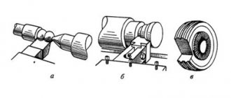
Turning is the most common cutting method and is used in the manufacture of axisymmetric parts such as rotating bodies (shafts, disks, axles, fingers, journals, flanges, rings, bushings, nuts, couplings, etc.). The main types of turning work are shown in Fig. 4.6.
Rice. 4.6. The main types of turning work (arrows indicate the directions of tool movement and workpiece rotation): a - processing of external cylindrical surfaces; b - processing of external conical surfaces; c - processing of ends and ledges; d - turning of grooves and grooves, a piece of workpiece; d - processing of internal cylindrical and conical surfaces; e - drilling, countersinking and reaming of holes; g - cutting external threads; h - cutting internal threads; and - processing of shaped surfaces; k - rolling of corrugations
In mechanical engineering, most parts receive their final shapes and overall dimensions as a result of mechanical processing of the workpiece by cutting, which is carried out by sequentially removing thin layers of material in the form of chips from the surface of the workpiece with a cutting tool.
Cutting tool
. When working on lathes, various cutting tools are used: cutters, drills, countersinks, reamers, taps, dies, threading heads, shaped tools, etc.
Turning cutters are the most common tool and are used for processing planes, cylindrical and shaped surfaces, cutting threads, etc. (Fig. 4.7).
Rice. 4.7. Turning cutters for various types of processing: a - external turning with a bent cutter; b - external grinding with a straight through cutter; c - turning with cutting the ledge at a right angle; g - cutting a groove; d — turning the radius fillet; e - boring a hole; g and h - cutting external and internal threads, respectively
Drilling is one of the common processing methods on lathes and is carried out to pre-process holes. Pre-cutting a hole in solid material can only be done using a drill. Depending on the design and purpose, drills are distinguished: spiral, feather, for deep drilling, centering, ejector, etc. Spiral drills are most widespread in turning.
The movement of the cutting tool during turning and its fastening on a screw-cutting lathe is ensured by several units (assembly units). Below is a brief description of how some of them work.
Rice. 4.8. Caliper: 1 - lower slide (longitudinal caliper); 2 — lead screw; 3 — transverse caliper slide; 4 - rotary plate; 5 - guides; 6 — tool holder; 7 — rotating head of the tool holder: 8 — screw for fastening the cutters; 9 — tool holder rotation handle; 10 - nut; 11 — upper slide (longitudinal support); 12 — guides; 13 and 14 — handles; 15 — handle for longitudinal movement of the caliper
The support (Fig. 4.8) consists of a lower slide (longitudinal support) 7, which moves along the frame guides using a handle 75 and ensures the movement of the cutter along the workpiece. On the lower slide, transverse slides (transverse slide) 3 move along guides 12, which ensure the movement of the cutter perpendicular to the axis of rotation of the workpiece. The upper slide 77 moves along the guides 5 of the rotary plate (using the handle 13), which together with the plate 4 can rotate in a horizontal plane relative to the transverse slide 3 and ensure the movement of the cutter at an angle to the axis of rotation of the workpiece. The cutter holder (also known as a four-position cutting head) is attached to the upper slide 77 using handle 9 and allows you to put the cutter into work with minimal time.
Rice. 4.9. Tool holder: 1 - washer; 2 - head; 3 - conical mandrel; 4 — handle; 5 — upper slide; 6 — four-sided cutting head; 7 - screw
The tool holder structure is shown in Fig. 4.9. A conical mandrel 3 with a threaded end is installed in the centering bore of the upper slide 5. A four-sided cutting head 6 is installed on the mandrel cone. When the handle 4 rotates, the head 2 moves down the thread of the conical mandrel 5. The washer 7 and the thrust bearing ensure a rigid fit of the cutting head 6 on the conical surface of the mandrel 3. Head 2 is attached to the cutting head 6 with screws 7. The cutting head is kept from turning when secured by a ball, which is wedged between the surfaces formed by the groove in the base of the conical mandrel 3 and the hole in the cutting head 6.
The tailstock of a lathe is primarily designed to support long workpieces during processing. It is also used to secure tools intended for processing holes (drills, countersinks, reamers) and for cutting threads (taps, dies, threading heads).
Rice. 4.10. Tailstock: 1 - body; 2 - center; 3, 6 — handles; 4 - quill; 5, 12 and 14 - screws; 7 - flywheel; 8 - traction; 9, 10 — levers; 11, 13 — nuts
The tailstock structure is shown in Fig. 4.10. In the housing 7 (when the screw 5 is rotated by the flywheel 7), a quill 4 moves, secured by a handle 3. A center 2 with a conical shank (or a tool) is installed in the quill. The tailstock is moved along the machine guides manually or using a longitudinal slide. In a stationary working position, the tailstock is fixed with a handle 6, which is connected to a rod 8 and a lever 9. The force of pressing the lever 9 with a rod 8 to the frame is adjusted with a nut 77 and a screw 72. A more rigid fastening of the tailstock is made using a nut 13 and a screw 14, which presses to bed lever 10.
On screw-cutting lathes designed for processing workpieces of complex configurations in mass production, various tools are secured in a multi-position rotary turret head. When rotating (indexing) the turret head, tools pre-set to size are sequentially put into operation.
Depending on the purpose, accessories for lathes can be divided into three groups:
- devices for securing workpieces;
- auxiliary tool for securing the cutting tool;
- devices that expand the technological capabilities of machine tools, i.e. allowing you to perform work that is not typical for these machines (milling, simultaneous drilling of several holes, etc.).
Devices for securing workpieces
. For fastening workpieces on lathes, two-, three- and four-jaw chucks with manual and mechanized clamping drives are used.
Rice. 4.11. Three-jaw self-centering chuck: 1, 2 and 3 - jaws; 4 — disk; 5 - gear; 6 — cartridge body
The most widely used is the three-jaw self-centering chuck (Fig. 4.11). Cams 7, 2 and 3 of the cartridge move simultaneously using disk 4. On one side of this disk there are grooves (shaped like an Archimedean spiral) in which the lower projections of the cams are located, and on the other there is a cut bevel gear mated to three bevel gears 5. When you turn one of the wheels 5 with a key, disk 4 (thanks to gearing) also turns and, by means of a spiral, simultaneously and evenly moves all three cams along the grooves of the cartridge body 6. Depending on the direction of rotation of the disk, the cams move closer to the center of the chuck or move away from it, clamping or releasing the part. The cams are usually made in three stages and are hardened to increase wear resistance.
There are cams for securing workpieces on the internal and external surfaces; when fastening on the inner surface, the workpiece must have a hole in which the cams can be placed.
Three-jaw self-centering chucks hold round and hexagonal workpieces or large diameter round rods.
Various shaped castings and forgings are secured in two-jaw self-centering chucks; The jaws of such chucks are usually designed to secure only one part.
In four-jaw self-centering chucks, square-section rods are fixed, and in chucks with individual adjustment of the jaws, parts of rectangular or asymmetrical shape are fixed.
Rice. 4.12. Types of centers: a - persistent; b - reverse; c - persistent half-center; g - with a spherical working part; d - with a corrugated surface of the working cone; e - with a carbide tip; 1 - working part; 2 — tail part; 3 - support part
Depending on the shape and size of the parts being processed, different centers are used (Fig. 4.12). The angle at the top of the working part of the center (Fig. 4.12, a) is usually 60°. The conical surfaces of the working 1 and tail 2 parts of the center should not have nicks, as this leads to errors in the processing of workpieces. The diameter of the supporting part 3 is smaller than the small diameter of the tail cone, which allows the center to be knocked out of the socket without damaging the conical surface of the tail part.
Rice. 4.13. Rotating center: 1 - working part; 2, 3 and 5 — rolling bearings; 4 — tail section
When processing with high cutting speeds and loads, rear rotating centers are used (Fig. 4.13). In the tail part 4 of the center, an axis is mounted on rolling bearings 2, 3 and 5, at the end of which the working part 1 of the center is made, which ensures its rotation together with the workpiece being processed.
Rice. 4.14. Turning clamps: a - regular: 1 - screw; 2 - shank; b - self-tightening: 1 - stop; 2 - shank; 3 - spring; 4 - axis; 5 - prism
Clamps (Fig. 4.14) serve to transmit rotation from the spindle to the workpiece installed at the centers of the machine. The clamp is put on the workpiece and secured with screw 1 (Fig. 4.14, a), while the shank 2 of the clamp rests against the pin of the driving chuck.
When processing a workpiece at centers, movement can be transmitted to it by a driver chuck through a driver pin and a clamp, which is attached to the part with a screw. To reduce auxiliary time during roughing, self-clamping driver chucks are used in the centers of shafts with a diameter of 15...90 mm.
Collet chucks are used primarily for securing cold-drawn rods or for re-clamping workpieces on a pre-treated surface.
Diaphragm cartridges are used when it is necessary to process a batch of workpieces with high centering accuracy.
The method of installing and securing workpieces on the machine is chosen depending on their size, rigidity and required processing accuracy. With a ratio of l/D < 4 (where l is the length of the workpiece being processed, mm; D is the diameter of the workpiece, mm), the workpieces are fixed in the chuck, with 4 < l/D< 10 - in the centers or in the chuck with pressing at the rear center (Fig. 4.15), with l/D> 10 - in the centers or in the chuck and the center of the tailstock and supported by a rest (Fig. 4.16).
Rice. 4.15. Installation of workpieces in the chuck with pressing at the rear center: 1 - workpiece; 2 and 3 - incisors
Rice. 4.16. Lunettes: a - movable; b - fixed: 1 - upper (folding) part; 2 - screws; 3 - bolts; 4 - cams or rollers; 5 — bar; 6 - bolt with nut
The most common is the installation of the workpiece being processed in the centers of the machine.
The workpiece is processed in centers if it is necessary to ensure the concentricity of the processed surfaces when reinstalling the workpiece on the machine, if subsequent processing is performed on a grinding machine, also in centers, and if this is provided for by the processing technology.
Workpieces with holes are installed in the centers using turning mandrels (Fig. 4.17).
Rice. 4.17. Turning mandrels: a - mandrel with a small taper (usually 1:2000): 1 - center hole; 2 - clamp; 3 - mandrel; 4 - workpiece; b - cylindrical mandrel: 1 - workpiece; 2 - mandrel; 3 — pressure washer; 4 — washer; c - expanding (collet) mandrel: 1 - workpiece; 2 - conical mandrel; 3, 5 - nuts; 4 - hollow mandrel; g - spindle mandrel: 1 - collet; 2 - workpiece; 3 - expanding mandrel; 4 - cartridge; d - mandrel with an elastic shell: 1 - plan washer; 2 - bushing; 3 - workpiece; 4 — hole for introducing hydraulic plastic; 5, 6 - screw
To facilitate the working conditions of workers when securing workpieces to machines, mechanized drives are installed: pneumatic, hydraulic, electric and magnetic.
Auxiliary tool
. To install and secure the cutting tool on the machine, an auxiliary tool is used, which largely determines the accuracy and productivity of turning.
As an example, consider an auxiliary tool for turret lathes. The operating principle of this tool is common to all lathes; Only the tail part, with the help of which the tool is installed on the machine, changes. On turret lathes, cylindrical holders, prismatic holders with cylindrical shanks and holders of complex shapes with cylindrical shanks, as well as bayonet holders are used.
The stops used on turret lathes to limit the feed of a bar or the rotation of a turret head with a horizontal axis of rotation can be rigid, adjustable, or folding.
Product control operations and the measuring instrument required for this will be considered when describing the technology for processing specific elements of parts (for example, cylindrical outer surfaces, holes, conical outer and inner surfaces). There will also be technological equipment for processing these surfaces, expanding the technological capabilities of the machines of this group.
Modifiers for fastening parts on a machine
To secure workpieces in the working space of the machine, chucks with 2, 3 and 4 jaws are used. They can be with mechanized or manual clamping drive. The most popular is the self-centering three-jaw chuck (Fig. 6). Together with disk 4, cams 3, 2, 1 move synchronously.
Rice. 6. Three-jaw self-centering chuck: 1, 2 and 3 - jaws; 4 — disk; 5 - gear; 6 — cartridge washer
At one end of the disk, grooves are made in the shape of an Archimedes spiral. The lower projections of the cams are installed in the grooves. A bevel gear is cut out from the other end of the disk. It is in mesh with three bevel gears 5. By turning one gear 5 with a special universal wrench, disk 4 is forced to rotate as a result of gear engagement.
All cams of the cartridge move synchronously through the spiral along the grooves of the housing 6. There are only two directions of movement: the cams tend to the axis of the chuck, clamping the workpiece, or move away, releasing it. Structurally, the cams are made with three stages. They are hardened to resist wear.
The jaws can grip parts while machining the outer and inner surfaces. The fastener inside the workpiece provides for a technological hole into which the cams fit. Self-centering chucks with three jaws hold hexagonal and round parts, and round bars with a large cross-section.
Self-centering dual jaw chucks hold forgings and shaped castings. Only one workpiece is secured in the jaws of such chucks. In self-centering chucks, rods with a square cross-section are attached to four jaws. Chucks with individual adjustment of the jaws hold products with an asymmetrical or rectangular configuration.
Rice. 7. Types of centers: a - center with emphasis; b - reverse center; c - persistent half-center; g - with a sphere; d - corrugated cone; e - with a tip made of hard alloys; 1 - working part; 2 - shank; 3 - support protrusion.
The dimensions and shapes of the workpieces make it possible to use different centers during processing (Fig. 7). At the top of the center workplace the angle is 60˚ (Fig. 7, a). The conical surfaces of shank 2 and workplace 1 must be smooth, without nicks. Otherwise, when processing parts, it will cause error.
The cross-section of the supporting protrusion 3 should be smaller than the small cross-section of the shank cone. This proportion makes it possible to knock the tool out of the socket, leaving the cone of its working part intact.
When working with high loads and cutting speeds, rear centers of rotation are used (Fig. 8). An axle is pressed inside the tail part of the center 4 on rolling bearings 2, 3, 5. It ends with working part 1 extending outwards. This allows the axis to rotate with the workpiece during processing.
Rice. 8. Rotating center design: 1 - working surface; 2, 3 and 5 - bearing; 4 - shank.
To transmit rotation from the chuck to the workpiece fixed at the centers of the machine, clamps are used (Fig. 9). The clamp is placed on the part and tightened with screw 1 (Fig. 9, a). The shank 2 of the clamp should rest against the pin of the driving chuck.
Rice. 9. Turning clamps: a - simple: 1 - bolt; 2 — tail section; b - with self-tightening; 1 - thrust screw; 2 — tail part; 3 - spring plate; 4 - finger; 5 - prismatic body.
When a part is processed in the centers, the movement is transmitted to it by a driver chuck through a driver pin through a clamp tightened on the workpiece with a screw. Drive self-clamping chucks help reduce the roughing time for shafts with a cross-section of 15...90 mm.
The purpose of collet chucks is to fasten cold-drawn rods. They are also used for re-fastening parts on a pre-treated surface.
Diaphragm cartridges are used to obtain parts with high centering accuracy.
Rice. 10. Arrangement of workpieces in the chuck using rear center preload: 1 - workpiece; 2 and 3 - incisors
Methods of fastening and installation of workpieces on a machine are used based on their hardness, processing accuracy, and overall dimensions. If the ratio I/D<4, where I is the length of the workpiece, mm, D is the cross-section of the workpiece, mm, then the workpiece is secured in the chuck.
If 4 <10, the workpiece is secured in a chuck with pressure at the rear center or at the centers (Fig. 10). If I/D>10, then the workpiece is placed in the center or chuck. Fastening in the center of the tailstock and support with a steady rest is practiced (Fig. 11).
Rice. 11. Installation of steady rests: a - with movement; b - without movement: 1 - tilting mechanism; 2 and 3 - bolts; 4 - roller mechanism; 5 — clamping bar; 6 - nut with screw.
The most popular installation of the workpiece is considered to be in the centers of the machine. It is installed in the centers if it is necessary to give it concentric surfaces. If further processing is carried out on a grinding machine, also in centers. This must be provided for in the processing flow chart.
Parts that have holes are attached in the centers using turning mandrels (Fig. 12). Mechanized drives help to facilitate the work of the machine operator in the operations of securing parts on machines:
- magnetic;
- electrical;
- hydraulic;
- pneumatic.
Rice. 12. Turning mandrels: a - mandrel with small taper (usually 1:2000): 1 - center hole; 2 - clamp; 3 - mandrel; 4 - workpiece; b - cylindrical mandrel: 1 - workpiece; 2 - mandrel; 3 — pressure washer; 4 — washer; c - expanding (collet) mandrel: 1 - workpiece; 2 - conical mandrel; 3, 5 - nuts; 4 - hollow mandrel; g - spindle mandrel: 1 - collet; 2 - workpiece; 3 - expanding mandrel; 4 - cartridge; d - mandrel with an elastic shell: 1 - plan washer; 2 - bushing; 3 - workpiece; 4 — hole for introducing hydraulic plastic; 5, 6 - screw
Metal processing on lathes
Lathes are used for single, small-scale, serial and mass production of the following parts and products.
- Bushings.
- Shafts of various configurations.
- Nuts.
- Gears.
- Couplings.
- Rings.
- Pulleys, etc.
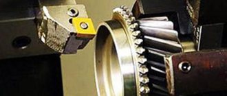
Photo No. 1: metal turning