Wet and dry wood
Wet wood usually processes better. The advantage is not only the simple and quick capture of material, but also the minimal dust formation during operation.
However, the resulting product will undergo major changes over time. Gradual drying can change the shape and size of the object. Rapid drying may even cause cracking.
Unlike fresh wood, when processing dry wood, you can count on stability of shape and final color. However, such turning work is more labor-intensive, but a number of modern devices solve this problem.
The lower availability and higher price of dried wood are also important.
How to become a professional
Turning can be studied throughout your life, since in addition to the theoretical part, a specialist must understand modern technology.
Progress does not stand still, which means there will always be an object of study. In addition, new samples of composite and polymer compounds are appearing among the materials being processed.
To master a profession, there are educational institutions and courses where highly qualified specialists pass on their experience to young students.
Information can also be gleaned from the Internet, where a variety of literature on turning is openly available.
The work requires good physical training, since very often turners suffer from a number of diseases. We can say that excellent health, advanced training courses and the ability to set up equipment will help you achieve the desired heights in your career.
Turning technology
Depending on the intention or the product to be produced, it is necessary to select a turning technique. The most common and simplest form is spindle turning, which is based on a cylindrical shape.
The firmly fixed material rotates smoothly around its axis, and special knives or planks shape the wood. In this way you make legs for chairs and tables, separate partitions for railings or fences.
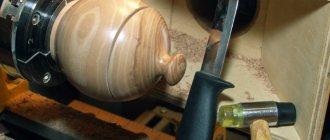
Longitudinal or transverse turning will be used in the production of decorative elements or bowls, containers and toys. Here you can interestingly combine mechanical processing of the material from the outside with modification of the cavity inside the tree.
Other types of turning include, for example, annular, multi-axis or segment turning. However, for normal wood processing, knowledge of classical techniques and their combinations is sufficient.
- When working, pay attention to high-quality equipment. It’s definitely not worth saving on knives.
- High-quality, well-sharpened steel guarantees ease of use.
- The material under the blade will change smoothly and there will be no unevenness or unwanted edge abrasion.
- Choose knives, lathes, chisels only from high-quality manufacturers with the possibility of repeated grinding.
Quality knives are an investment, but it will come back to you soon. This will save your time, complex repairs of finished products and damaged material.
Features of turning. Video examples
The essence of the metal processing process is as follows:
- machine movements are carried out in clear directions;
- the spindle of the device, together with the workpiece, rotates along the Z axis, which is the starting point in operation;
- the straight X axis must be strictly perpendicular to the Z axis;
- the cutters should be located in the XZ plane;
- The distance to the cutter must be adjusted when applying equipment.
In modern lathes there is a third coordinate, which is equal to the angle of the main spindle. This indicator can be set and adjusted using software.
Types of lathes
The most popular device for metal processing is the screw-cutting lathe, which is highly versatile. It is used in large enterprises, as well as in single and small-scale production.
In addition , there are other types of lathes:
- Screw-cutting lathes.
- Semi-automatic multi-cutting devices for serial and large-scale production.
- Turning-rotary two- or single-column.
- Turret lathes designed to work with complex products.
- Modern turning and milling complexes.
To produce parts with particularly precise diametrical and linear geometric parameters, programmable machines are used. In their design they are almost no different from universal ones.
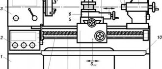
Structure of a lathe
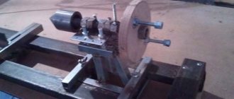
The universal center lathe is the most common lathe. The name of a lathe comes from two points between which the workpiece is clamped in the center.
The structural elements of a lathe can be divided into 5 main groups:
- Bed in the form of a massive cast base;
- Headstock and tailstock;
- Feeding device;
- Longitudinal or transverse support;
- Set of replacement gears;
- Transmission.
Some lathes are additionally equipped with an apron to drive the mechanisms.
Lathe bed
This is the main part of the lathe, it is shaped like a beam and is usually made of gray cast iron. The bed must be rigid and strong enough to support the weight of other parts of the lathe, not bend, and withstand the forces encountered during turning.
- The lathe bed is usually mounted on two frame legs.
- The left leg mainly hides the engine and gearbox, the right one serves as a toolbox.
- At the top of the bed there is a guide for the support and tailstock.
- The feeder slides on outer guide surfaces and the tailstock slides on inner guide surfaces.
Due to possible damage, tools and semi-finished products are not placed on it; storage compartments are provided for this purpose.
Lathe headstock
It is a hollow shaft mounted in bearings designed to prevent bending of the spindle and maintain the pressure generated during machining.
- The front and rear main bearings (sliding) perceive pressure perpendicular to the spindle axis.
- These pressures are also called radial pressures.
- The pressure in the direction of the spindle axis (axial pressure) is absorbed by the rolling bearing.
- The spindle and headstock should not vibrate during operation.
Most lathes have a box-shaped headstock (in exceptional cases they are cylindrical).
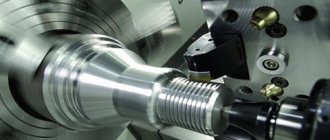
The right end of the spindle protrudes from the headstock and has a thread on the outer end to which a clamp is screwed for clamping the workpiece. The main part of the headstock is the spindle.
Spindle
The spindle is driven by a motor, which, as already mentioned, is installed in the left rack of the lathe. The motor shaft has a drive pulley with grooves for drive belts that transmit motion to the driven pulley and the gearbox.
- A gearbox has multiple gears, and the movement of the sliding gears changes the gears and therefore the speed of the drive pulley.
- The movement from the drive pulley is transmitted by a wide flat belt to a pulley in the headstock.
- The pulley is mounted on a housing mounted on two ball bearings.
The spindle passes freely through the housing and can be connected to it using a coupling or gear template.
Feeder
During turning, the knife is moved manually or mechanically, radially and axially relative to the workpiece. The feeder is driven by a shaft and replaceable gears. The movement is transmitted to gears in the feed reducer.
Shifting gears changes the speed at which the blade feeds when turning.
- In the feed mechanism, the gears are divided into three groups I, II, III. In Part I, the gears are changed by moving the sliding gears using a flywheel.
- Part II introduces the Norton gear, which is driven by an intermediate shaft on which is mounted a wide pinion, with which the pinion is constantly in mesh, mounted on a swing arm.
Wood turning is a beautiful and creative activity. It takes some skill, but with quality equipment and a powerful lathe, you can master the basic techniques relatively quickly.
In addition, treated wood is widely used. You can equip or complement it with conventional furniture production, it will also serve as a practical accessory in the interior and exterior.
Video course by Viktor Leontiev “Turning” and educational videos
- 1.1. The device of a screw-cutting lathe
- 1.2. Control of a screw-cutting lathe
- 1.3. Lathe Maintenance
- The device of a screw-cutting lathe. Educational video
- Purchase, operation and repair of a TV-4 lathe. Educational video
- Design and principle of operation of a CNC lathe. Educational video
- 2.1. Operating the Three-Jaw Chuck of a Lathe
- 2.2. Installing the chuck on the machine and checking the centering accuracy
- 2.3. Boring and lapping of lathe chuck jaws
- 2.4. Restoring the lathe spindle mounting base
- 2.5. Quality control of lathe chucks
- 3.1. Measuring with calipers on a lathe
- 3.2. Micrometer measurements on a lathe
- 4.1. Concept of the cutting process on a lathe
- 4.2. Cutters for metal lathe
- 4.3. Tool steels
- 4.4. Hard alloys and materials
- 4.5. Super hard cutting materials
- 4.6. Heat generation during metal cutting
- 4.7. Cutting force and machine rigidity
- 4.8. Tool deformation and its causes
- 4.9. Rigidity of fastening parts
- 4.10. Deformation of treated surfaces
- 5.1. Installing cutters on a lathe
- 5.2. Using Limbs
- 5.3. Axial stops on a lathe
- 5.4. Working with longitudinal feed stops
- 5.4.1. Working with a universal stop
- 5.5. Cross and axial feed stops
- 6.1. Size, deviations, tolerance when processing workpieces on a lathe
- 6.2. Tolerances and fits when processing on a machine
- 7.1. Positioning of workpieces during processing on a machine
- 7.2. Bases and base sets
- 7.3. Cylinder alignment
- 8.1. Sharpening machines and wheels
- 8.1.1 Basic rules for working on grinding machines
- 8.1.2 Installing the grinding wheel
- 8.1.3 Dressing grinding wheels
- 8.1.4 Retrofitting tabletop sharpening machines
- Sharpening drills for drilling sheet material
- Sharpening turning tools on a technological plate
- Sharpening the front surfaces of turning tools
- Sharpening drills with flat back surfaces
- Sharpening taps
- Non-standard drill sharpening
- 9.1. Measuring metal temperatures based on heat and tarnish colors
- 9.2. Metal hardness measurements
- 9.3. Internal stresses in metals
Operation of a universal screw-cutting lathe
Three jaw chuck
Measuring tools
Cutting theory
Getting started on a lathe
Tolerances and landings
Practical basing of parts
Working on grinding machines
Measuring the hardness and temperatures of metals
Photos of wood turning
Cutting tool
The tools required for turning are usually solid or compound cutters with a rectangular shape. Composite tool inserts can vary in size and shape, but are usually shaped like a square, triangle, or diamond. The tool is inserted into the machine support seat and fed to the rotating workpiece for cutting. Cutting tools are classified according to:
- Cutter extension angle – from 0 to 800;
- The shape of the working end is square or pointed;
- Direction of movement with a support – right- or left-handed;
- Cutting edge material – steel or carbide.
In addition to cutters, drills, cutters, taps, reamers, etc. are used as working tools on lathes.
Milling cutters, in particular, are cylindrical multi-point cutting tools with sharp teeth located on the outside. The spaces between the teeth are called grooves and allow chips to flow away from the workpiece. The teeth can be straight or helical; the presence of a helix angle along the side of the cutter, but more often they are located in a spiral. The spiral angle reduces the load on the teeth due to the redistribution of forces. The more teeth, the better the quality of the resulting surface.
All cutting tools used in turning can be made of tool steels or carbide alloys. The selection criteria are hardness, impact strength and wear resistance of the tool.